Kentaro, Lee, Daniel, Nutsinee
While tackling noise on high CLF power antisqueeze trace we found the source of mysterious CLF 'scatter shelves' to be the high SHG gain.
One might remember the weird looking shelves on the CLF error signal at 4kHz and 20kHz (alog46679 and alog47222).
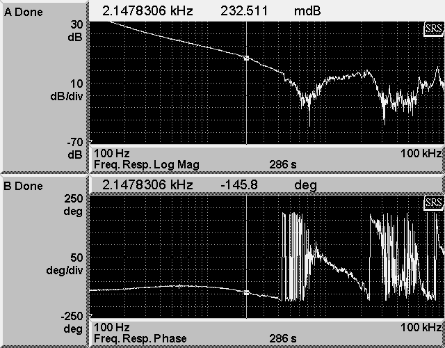
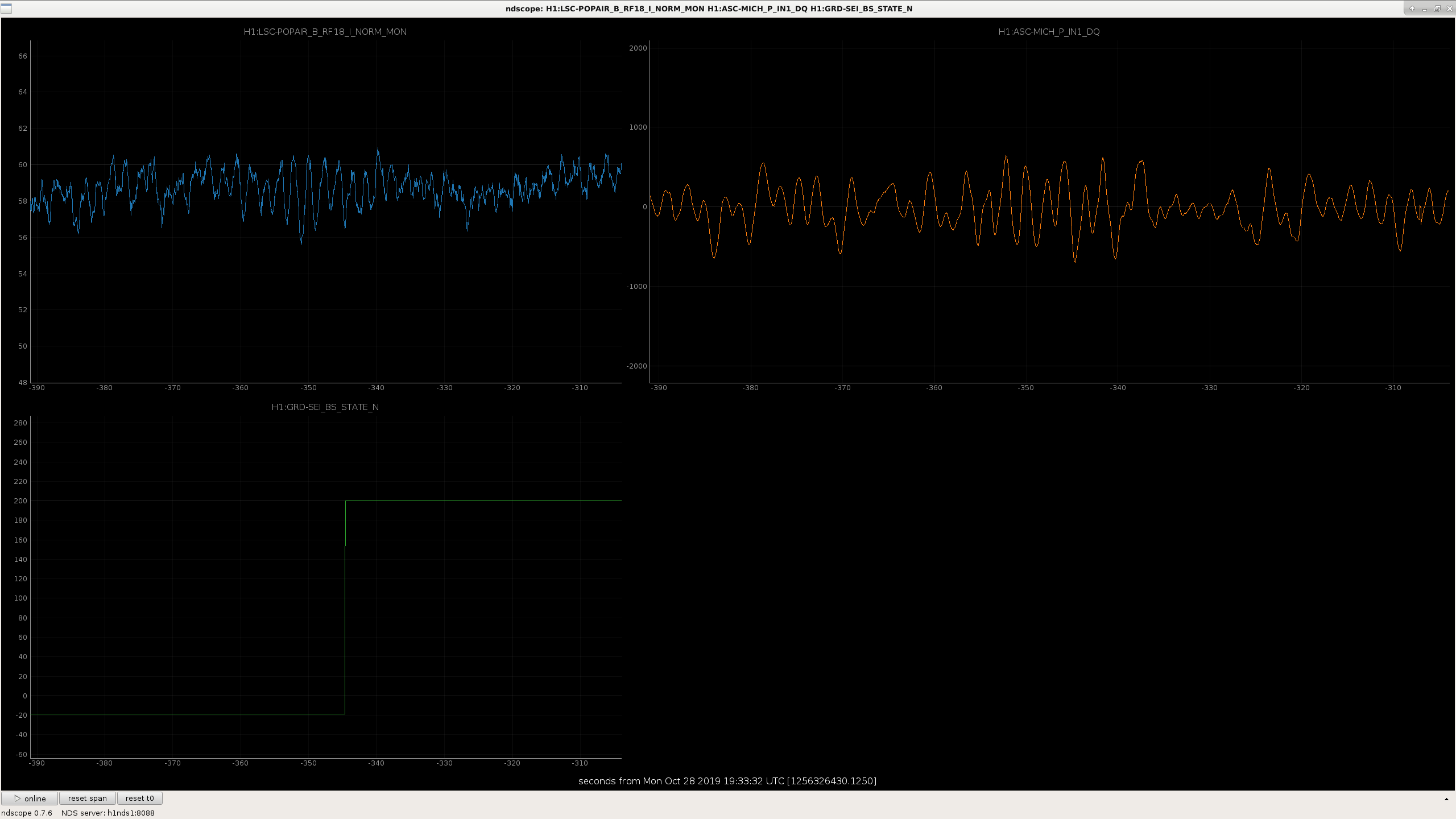
Plot attached was taken today at 40uW transmitted CLF power, with high SHG gain being 30-31dB (~2kHz SHG transfer function UGF, see attached GIF file) and low SHG gain being 7dB (~200Hz SHG UGF). The 4kHz shelf isn't prominent here compared to the past alogs that's likely because the data was taken with relatively low CLF power, the 20kHz shelf however, is now gone. The broad peak at 5.5kHz is likely due to gain peaking as we were operating at higher CLF UGF than usual (that was not intentional, better CLF data is coming). We looked at the same comparison on Sunday with higher CLF power and saw that 4kHz shelf was eliminated (data was saved, but unretrievable).
At high SHG gain we had 35 deg phase margin on the SHG loop. We suspect the shelves were caused by SHG mechanical noise. Since then we have been operating at 7dB common gain where we no longer observe this coupling in CLF. This sadly put SHG UGF at 200Hz.
Note that this still doesn't solve the problem with worsen squeezing at high CLF power.
Jenne, Chiara.
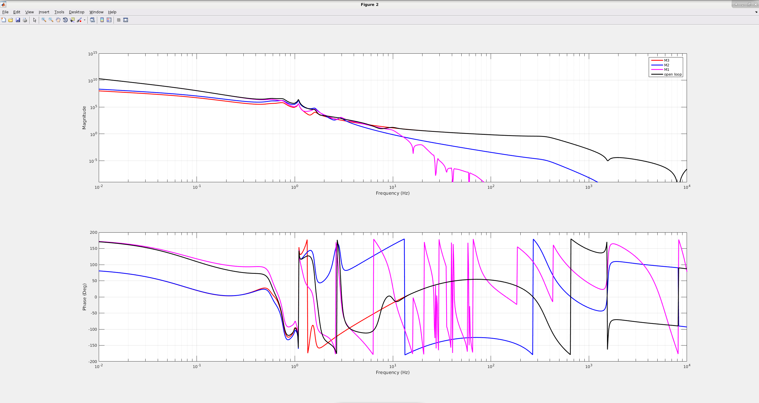
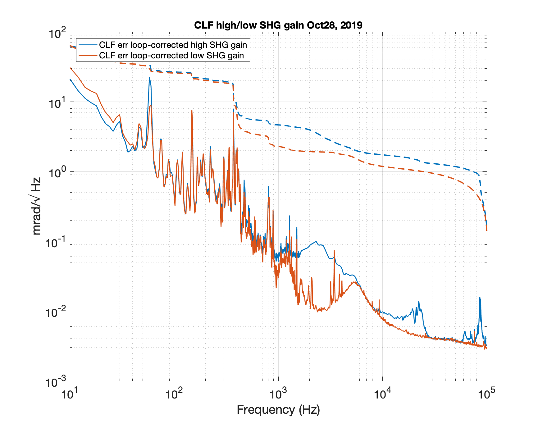
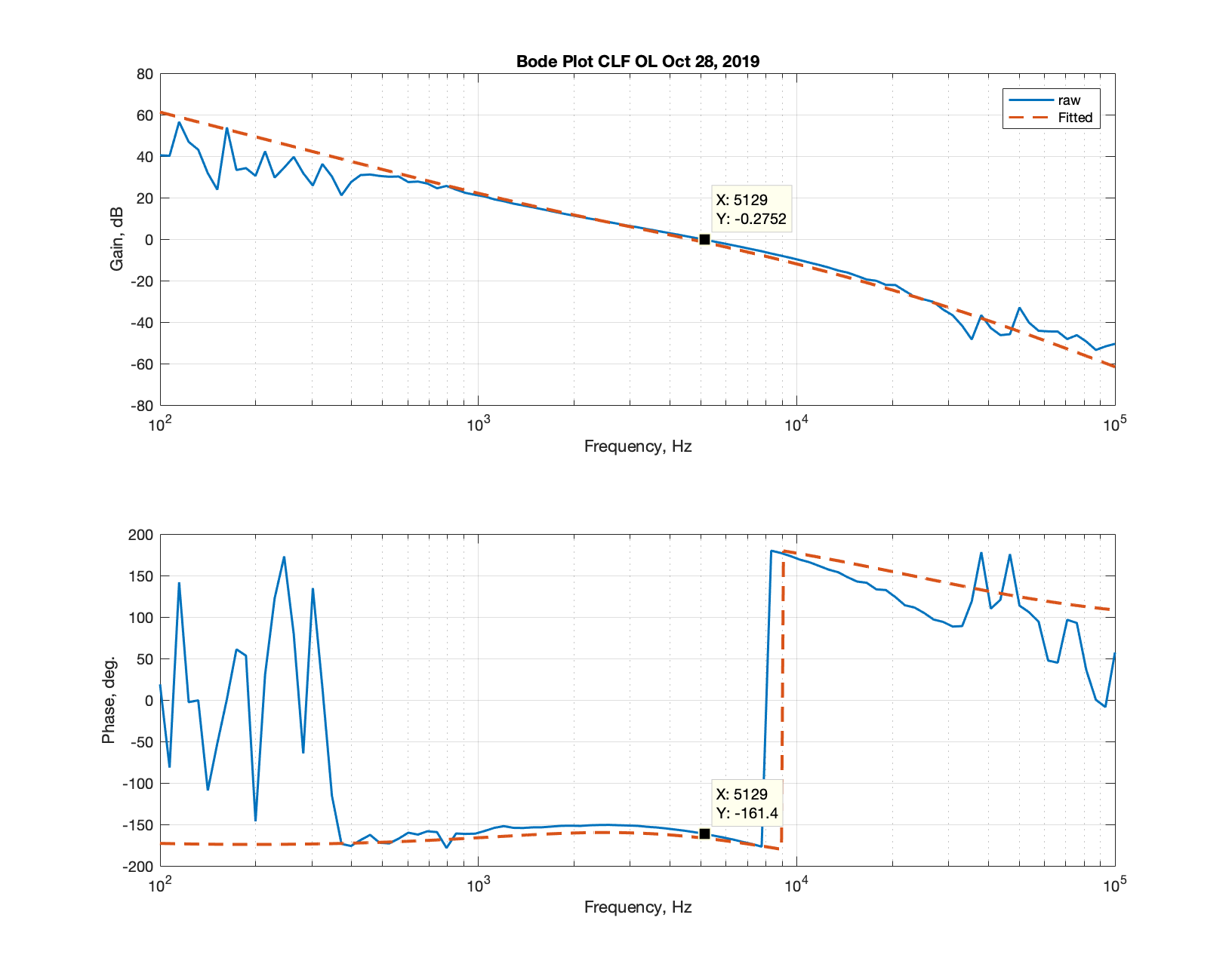
As a firts test, in preparation for future simulations and measuments with PRCL during ISI differential control, we plotted traces for M1, M2, M3 and open loop gains (in attachment). This is useful to understand if/where flters need to be modified.
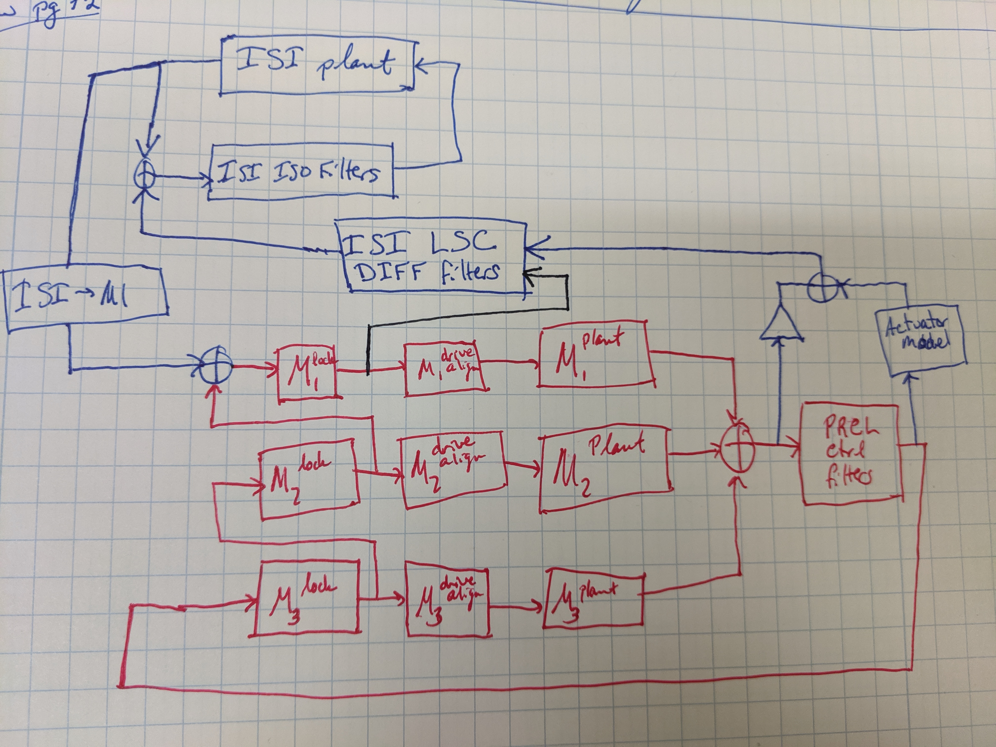
The second figure shows the loop diagram we think should work when insertng controbution from PRCL (red part). Two different ways are considered to connect PRCL to ISI, shown in blue and black, and not considered yet in the previous model.
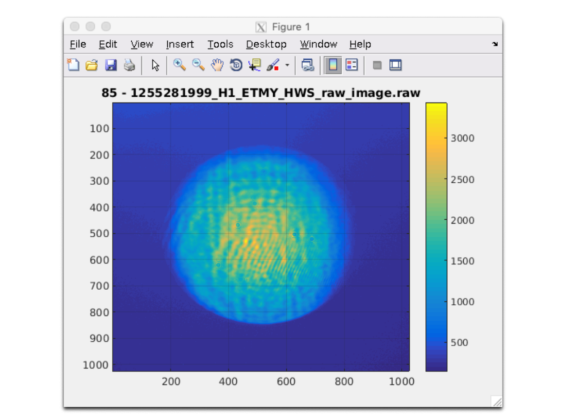
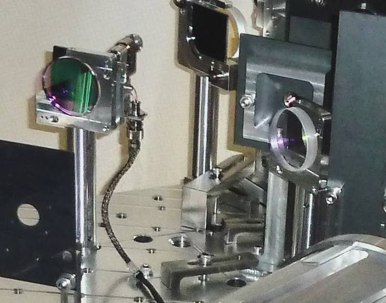
While we were down for the earthquake and 50 mph winds I tweaked up the alignment of the end-y Hartmann.
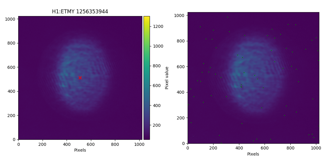
I followed Aidan's handy instructions, mostly adjusting HWS M1A, and got a return beam as shown in the first attachment. There are two sets of diagonal fringes to the left and right of the beam. Previously (see second attachment for a screenshot from the instruction manual) the fringes were on the center and left of the beam, so perhaps it is still a bit miscentered in yaw? I'm not sure why, but the beam is dimmer now than it was previously.
Some notes:
[Chiara, Jenne]
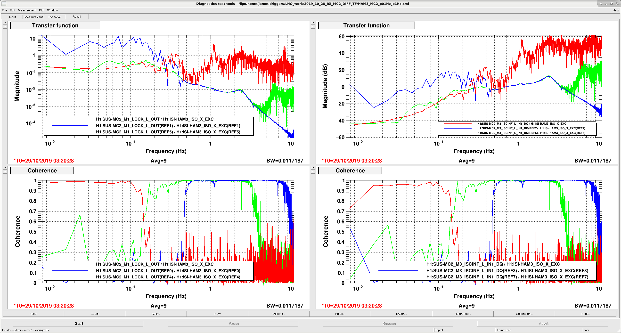
It's pretty windy and earthquake-y, so we took some time to measure the HAM3 to MC2 transfer function (so we don't have to do this in the morning during maintenance).
We drove at the error point of the isolation loop in X, since that is where our MC2 length offloading will inject. We monitored MC2 both at the M1_LOCK_L_OUT and at the the M3_ISCINF_IN1 (although I should have probably taken the output of the ISCINF filter).
We did bandpassed white noise injections, in 3 different bands, to see some coherence. In the attached screenshot, the left plot is with the M1 stage as the monitor point, while the right is M3. The red is coherent up to about 0.1 Hz, the green traces are coherent between about 0.2 Hz - 2 Hz, and the blue traces are coherent from about 0.5 Hz to 8 Hz. We'll need to extract the data and stitch these together to make one single nice measurement, but then we can use this to help design our suspension length offloading. The measurement in the left plots looks very similar to the LLO version of the measurement, reported in LLO alog 49151 (blue trace in 1st fig).
[Sheila, Craig, Timesh]
Cal SVN root: /ligo/svncommon/CalSVN/aligocalibration/trunk
This morning, Sheila took the usual sweep of measurements for calibration at around 15:56:49 UTC. When looking at the results from the processing sensing script, we see an antispring at f_s = 4 Hz. Attached to this alog is the raw data, the MCMC model with the measurement, the reference model with all the measurements and MCMC corner plot of this measurement.
We tried to re-measure the the Open Loop Gain (OLG) at around 01:10:13 UTC during which, the PCAL measurement ran successfully however the OLG measurement failed due to an earthquake. Before re-running the measurement we set H1:LSC-SRCL1_OFFSET from 100.0 counts to 0.0 counts. The steps in offset was to make sure that there was not a large loss of power in the arms and have the ability to quickly restore the IFO if required. The motivation for changing the offset was that in O3a, a value of 100.0 counts was used to compensate for a pro-spring (for example, see LHO alog 51440 and comment therein) and since we are measuring an anti-spring with the same counts offset, we may have been driving an anti-spring. The hypothesis is that by removing the offset, the spring would tend towards zero.
We were able to collect OLG data from 1083.7Hz down to 10.334Hz before the lockloss. This is not sufficient for re-measuring the spring/anti-spring of the IFO thus, we will attempt to repeat the OLG measurement once the IFO is back into nominal low noise (NLN) and has thermally equilibrated. The dtt files and processing scripts that were used are given below for the original measurements and the re-run measurements (svn revision given in brackets):
Sensing:
^/Runs/O3/H1/Measurements/FullIFOSensingTFs2019-10-28_H1_DARM_OLGTF_LF_SS_5to1100Hz_15min.xml (r8632)
^/Runs/O3/H1/Measurements/FullIFOSensingTFs2019-10-28_H1_PCALY2DARMTF_LF_SS_5t1100Hz_10min.xml (r8632)
^/Runs/O3/H1/Measurements/FullIFOSensingTFs2019-10-28a_H1_DARM_OLGTF_LF_SS_5to1100Hz_15min.xml (r8632)
^/Runs/O3/H1/Measurements/FullIFOSensingTFs2019-10-28a_H1_PCALY2DARMTF_LF_SS_5t1100Hz_10min.xml (r8632)
Actuation:
^/Runs/O3/H1/Measurements/FullIFOActuationTFs/2019-10-28_H1SUSETMX_L1_iEXC2DARM_10min.xml (r8632)
^/Runs/O3/H1/Measurements/FullIFOActuationTFs/2019-10-28_H1SUSETMX_L1_PCAL2DARM_8min.xml (r8632)
^/Runs/O3/H1/Measurements/FullIFOActuationTFs/2019-10-28_H1SUSETMX_L2_iEXC2DARM_12min.xml (r8632)
^/Runs/O3/H1/Measurements/FullIFOActuationTFs/2019-10-28_H1SUSETMX_L2_PCAL2DARM_6min.xml (r8632)
^/Runs/O3/H1/Measurements/FullIFOActuationTFs/2019-10-28_H1SUSETMX_L3_iEXC2DARM_12min.xml (r8632)
^/Runs/O3/H1/Measurements/FullIFOActuationTFs/2019-10-28_H1SUSETMX_L3_PCAL2DARM_6min.xml (r8632)
Sensing:
Reference model: modelparams_H1_20190909
^/Runs/O3/H1/Scripts/FullIFOSensingTFs/process_sensingmeas_20191028.py (r8636)
Actuation:
Reference model: modelparams_H1_20190416
^/Runs/O3/H1/Scripts/FullIFOSensingTFs/process_actuationmeas_20191028.py (r8637)
[Craig, Timesh]
We re-measured the sensing by re-measuring the OLG and PCALY. Before re-running the measurement we set H1:LSC-SRCL1_OFFSET from 100.0 counts to 0.0 counts. The Earth stayed quiet enough that we now see a ~9Hz pro-spring after the successfully completion of both measurements. Once again the raw data, the MCMC model with the measurement, the reference model with all the measurements and MCMC corner plot of this measurement are attached to this alog.
I am uncertain what the reason is, or the cause of, the pro-spring/anti-spring in these scenarios.
I'm not confident that the above 0ct SRCL offset data is really a "9 Hz pro spring," and Sheila and I are not so confident it's really bad just yet. (Where "bad" would be "enough of a low frequency response that would drive us to change the sensing function model in the front-end.") I've compared the above two data sets against the last few data sets of O3A in the attachment below. One can see that, although, indeed a 100 ct SRCL offset is an anti-spring, the 0 ct offset data residual looks much like the subtle residual mixing of a detuned SRC and some sort of L2A2L crosscoupling (or whatever label you want to put on the as-of-still-poorly-understood low frequency response that's *not* a detunement of the SRC) that we saw at the tail end of O3A *after* installing the 100 ct offset. Also note that there's no magic to the numbers here: they're all determined by "quick" tests -- easy changes in the IFO configuration that need confirming with ~25 minutes of measurement. We started with no digitally requested offset (0 ct) for most of O3A, and then on one Wednesday after sorting out our August spot position kerfuffle, we tried 100 ct, then 200 ct to try to reduce the severe pro-spring with which we ended up. 200 ct seemed unstable, and 100 ct conveniently seemed to give us the "no detuning" response we wanted. Now, the quick test was "turn it off," and *that* got us close enough, so we're running with that for now. Sadly, we've yet to put together a model that's complete enough to help us understand and/or predict what's going on. So, for now, if we can get the IFO stable enough for us to have the patience to do some more exploring, we'll measure the sensing function again to make sure this new answer -- with 0 ct SRCL offset -- is consistent, or if the resulting low frequency response moves around with time.
Taking a look at the work Timesh did to process the 2019-10-28 actuator data, the answers are
UIM PUM TST
Reference Model 7.67e-08 (N/ct) 6.036e-10 (N/ct) 4.727e-12 (N/ct)
MCMC Fit 7.564e-08 (N/ct) 6.065e-10 (N/ct) 4.781e-12 (N/ct)
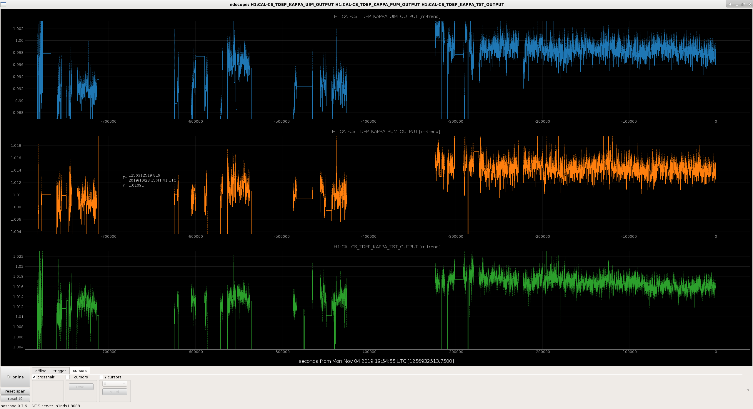
kappa via MCMC 0.986054 1.00483 1.0115
kappa via CALCS 0.995 1.0107 1.0133
So these should be close enough that we don't need to update the actuator coefficients.
Note that these will have similar 0.5% levels of systematic error that have been reported by the PCAL system in 52893 from having the wrong ETMX test mass mass. To be determined how we'll rectify this....
I made an adjustment at the end of the day (bad idea!) which may result in PT199 drifting above the alarm threshold of 100 psi. If so, please ignore any resulting alarm. I am monitoring and will tweek tomorrow if required.
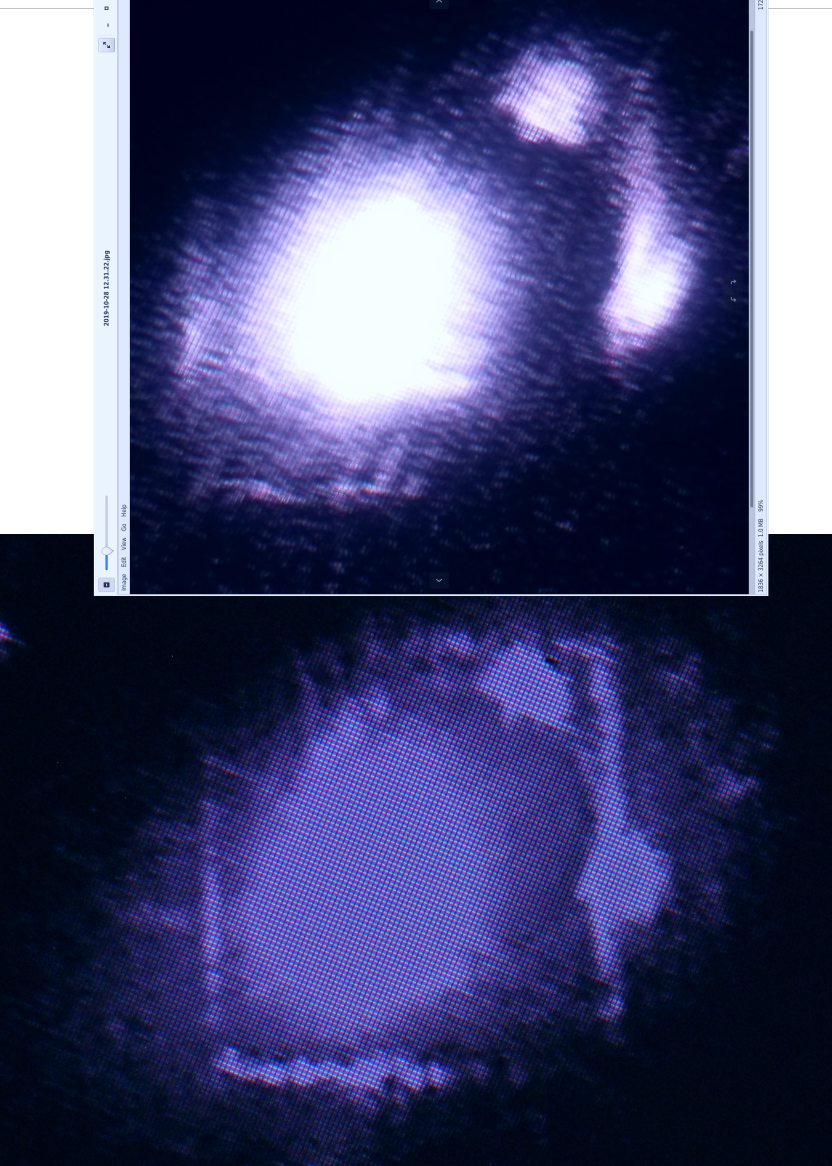
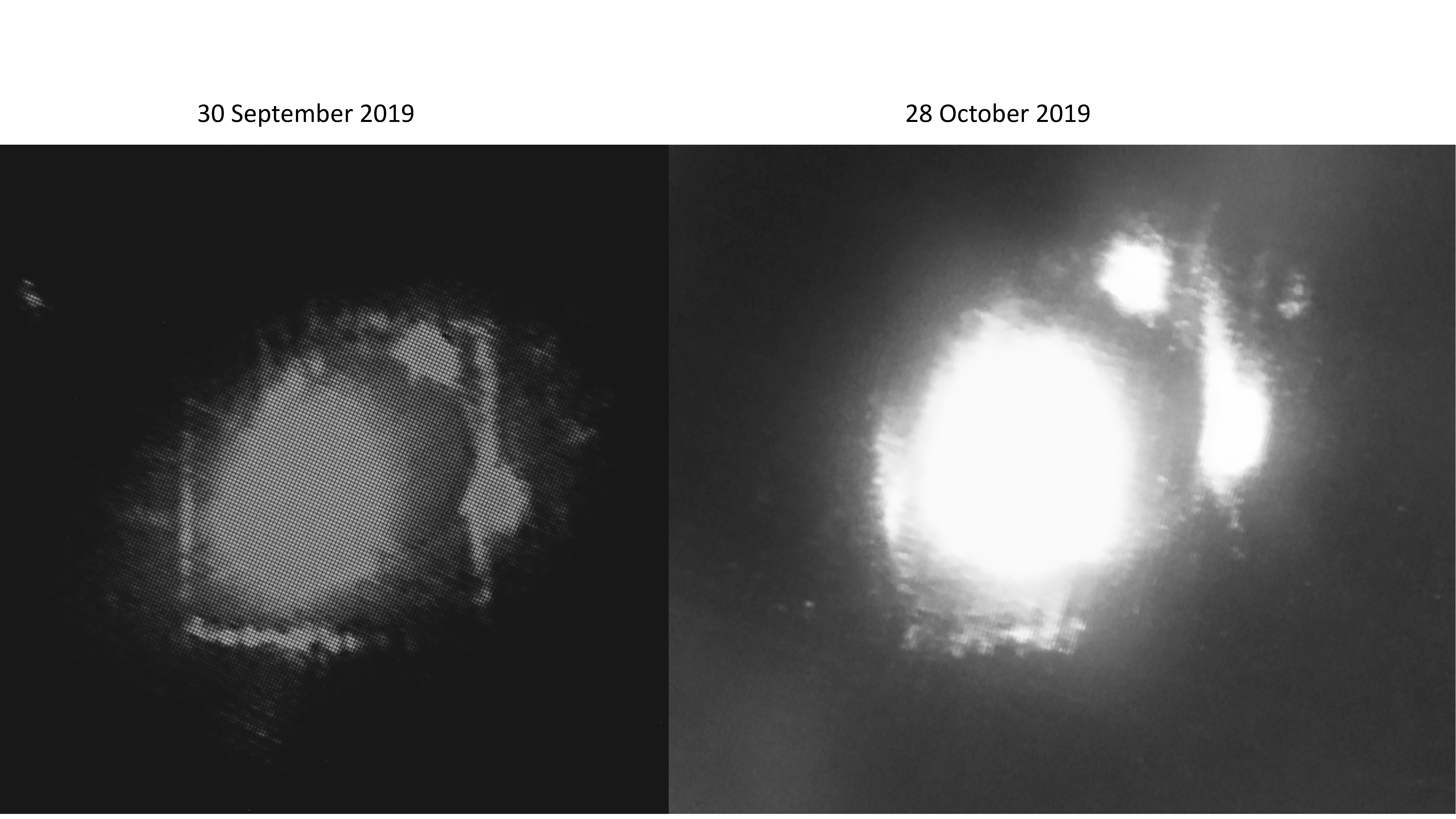
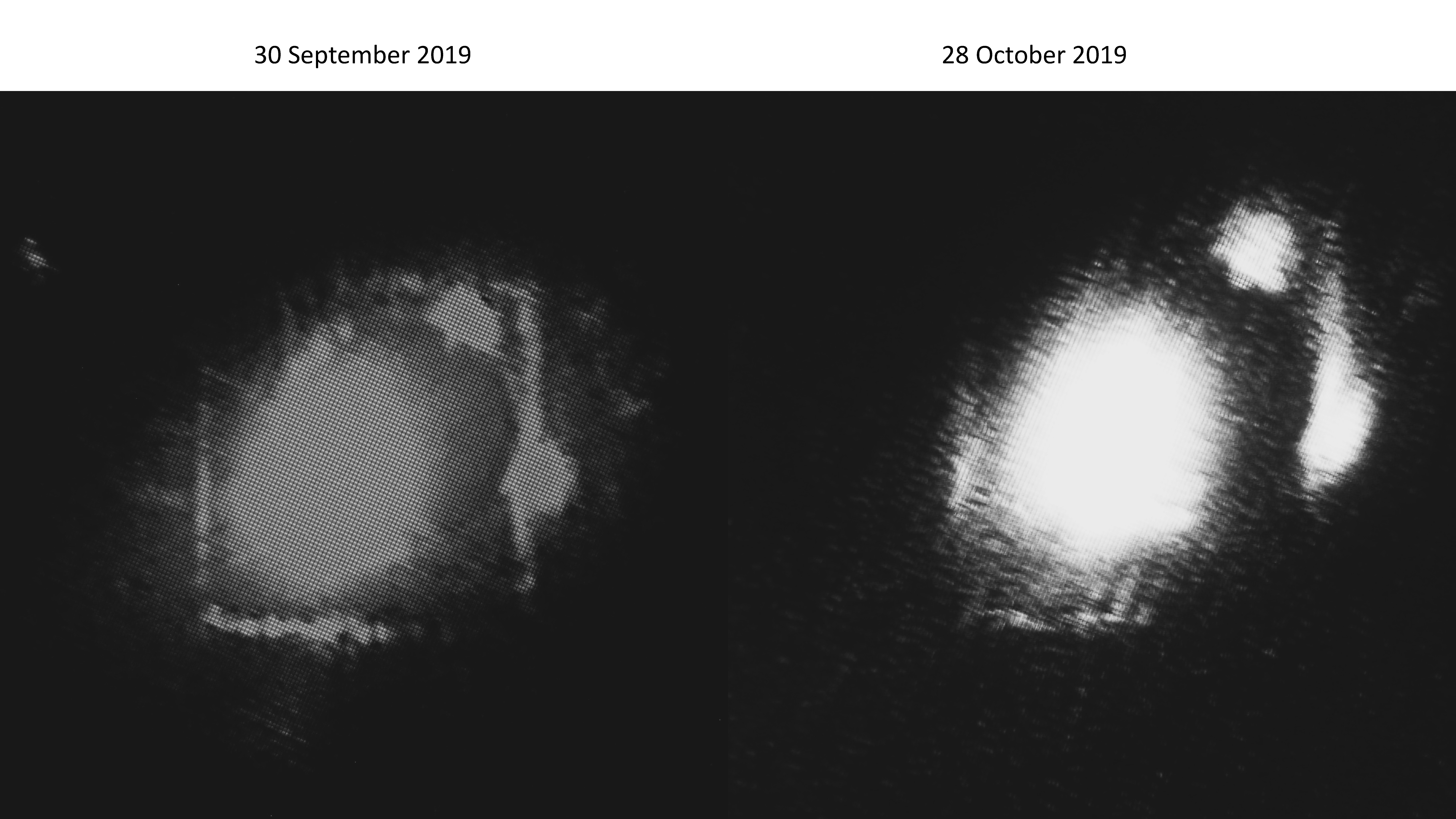
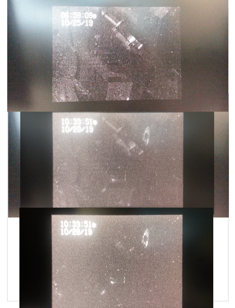
There are some changes to the beams on Calcite Wedge 1, seen on the analog camera. Images attached show that the stray beam on the right side of the image was round on 30 Sept. 2019, and now has a tapered side. Under the beam there are now vertical lines of IR light, where none were before.
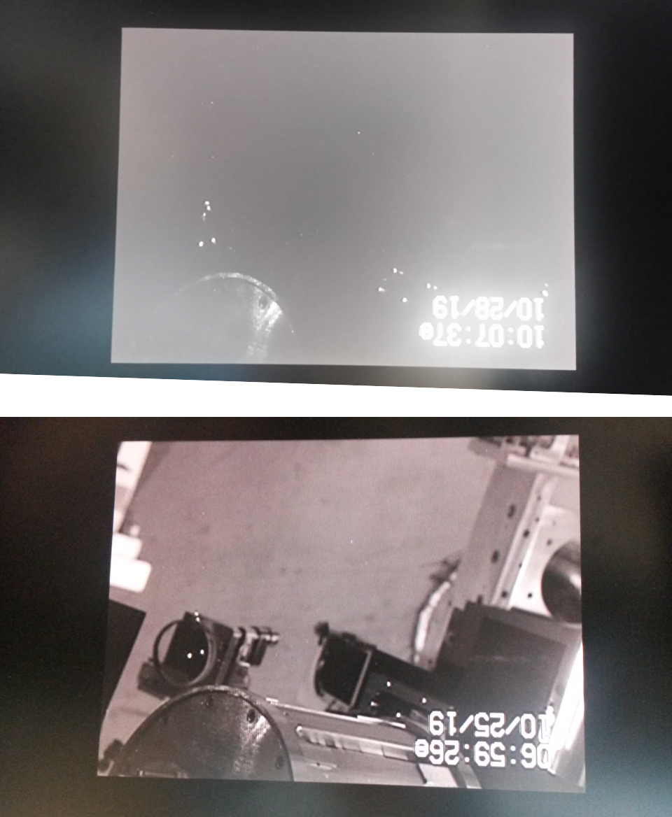
The HAM2 East Door analog camera is looking at the steering mirror for the ISS Second Loop, and the back of AOE1 baffle.
In the past I've alogged that the ISS 2nd Loop steering mirror has multiple beams, alog 48801, images 6 and 8 from the left.
The first attachment show two images of the the ISS 2nd Loop steering mirror, AROM RH2, and the back of AOE1, one image with the illuminator on, so this image has both visible light and IR light (bottom), and one image with IR only (top), and in both images one can see multiple beams on the 2" steering mirror and the frame of AOE1.
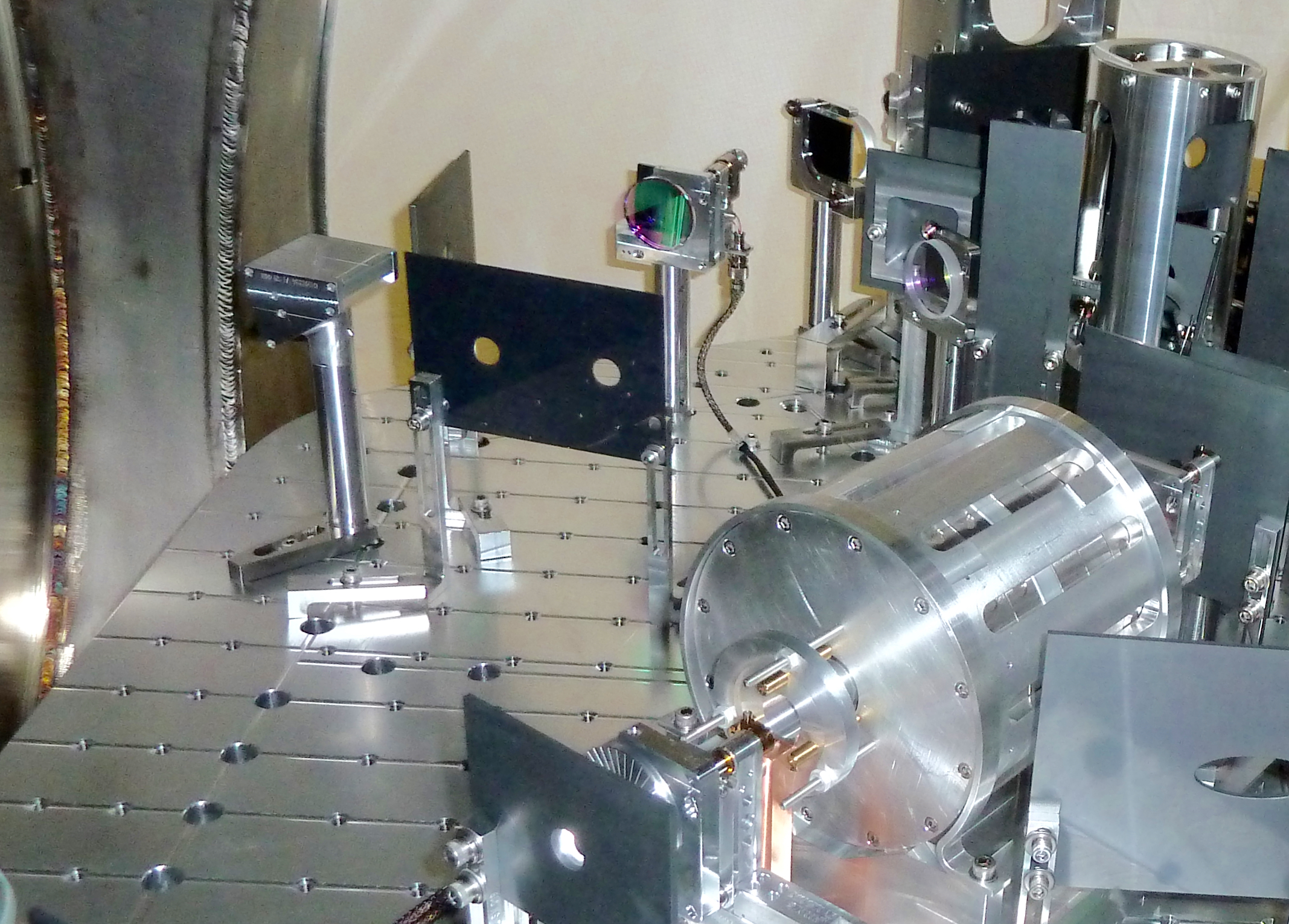
The next two images show the approximate view of AROM RH2 and AOE1 from the East side of HAM2, at a much higher viewing angle than is possible with the current camera setup.
The last image shows AOE2.
AOE1 and AOE2 were originally inteded to have SiC baffle plates on both sides of the frame, however, at the time of install only 2 SiC plates were available, so the descision was to install the first plate for AOE1 and AOE2.
Created FRS 13760, and have added it to WHAM2 Issue Tracker FRS 5117.
Sheila, Patrick Attached is a list of alignment values and their differences for Sep 27 2019 20:59:42 UTC (1253653200) and Oct 28 2019 20:39:42 UTC (1256330400). Both of these times are at NLN. The values are taken from minute trend means.
Script and results attached for slider values calibrated in microradians.
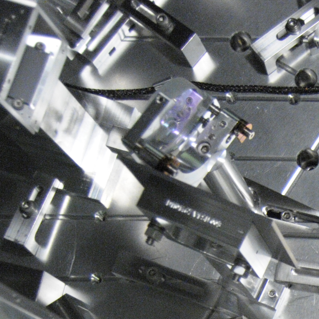
The IO Faraday Isolator Forward Rejected Beam is missing it's steering mirror, and dumping a beam on the front of AOE2 and on the frint of the IO beam dump.
In the first image, the top image is the camera view with no IR light, showing the AOE2 baffle, ROM RH11, the steering mirror for the IO faraday forward rejected beam (IO FI FRB), and the beam dump for the IO FI FRB. The bottom image is from today, H1 in NLN at 37W, showing a halo around the AOE2 aperture and a bright beam, which is part of the IO FI FRB. Part of the IO FI FRB is hitting ROM RH11, and landing on the front of the beam dump, this means that part of the beam is also scattering from the barrel of ROM RH11.
The additional images show these components on HAM2 with IR light, and visible light, and include a diagram of where the IO FI FRB is intended to go.
There is a chance that this could be resolved with changing the alignment of IM3, however, it's equally likely that the angle of the main beam through the IO Faraday is contributing to this issue, and a combination of IM2 and IM3 may be needed to steer the FRB back into the beam dump. It's also possible that IM1, IM2 and IM3 will need to be adjusted to steer the beam back into the beam dump and also restore the pointing of the main beam into the interferometor, as much as possible.
TITLE: 10/28 Day Shift 15:00 – 23:00 (08:00-16:00), all times posted in UTC
STATE of H1: Planned Engineering
INCOMING OPERATOR: None
SHIFT SUMMARY: Locked shortly after shift start, lost lock around 10:30. Had trouble re-locking, Sheila aligned IM3 and PR3 to increase COMM beatnote. Lost lock again about 2.5 hours later, likely due to PEM injections. Re-locking, currently at ACQUIRE_DRMI_1F.
LOG:
15:06 (08:06) Tyler driving forklift outside corner station
15:11 (08:11) Tyler finished
15:42 (08:42) Vlad to Optics Lab
16:53 (09:53) Robert, Phillipe to LVEA
16:54 (09:54) Jeff to mechanical room - check TCS chillers
16:58 (09:58) Patrick to H2 -- IO chassis testing
17:03 (10:03) Hugh to Optics Lab -- open fume hood for evaluation
17:04 (10:04) Jeff back from mechanical room
17:30 (10:30) Lockloss from NLN
17:55 (10:55) Timesh, Gavin to EX -- pick up NCAL equipment
18:04 (11:04) Richard to MX, MY -- find cable
18:24 (11:24) Timesh, Gavin back from EX
18:25 (11:25) Timesh, Gavin to Optics Lab -- drop off equipment
18:27 (11:27) Richard back from mid-stations
18:29 (11:29) Timesh, Gavin back from Optics Lab
18:56 (11:56) Patrick back from H2 building
19:17 (12:17) Robert, Dan to LVEA -- look at ISCT1
19:26 (12:26) Robert, Dan out of LVEA
19:29 (12:29) Jeff, Charles to Optics Lab -- look at chemicals
19:30 (12:30) Patrick to H2 building -- continue testing
19:46 (12:46) Patrick back from H2
19:48 (12:48) Hugh, Jeff out of Optics Lab
21:44 (14:44) Sheila, Lee to LVEA -- look for GPIB adapter near PSL racks
22:03 (15:03) Betsy to Optics Lab
22:35 (15:35) Sheila to LVEA -- clear out troublemakers
22:40 (15:40) Sheila out of LVEA
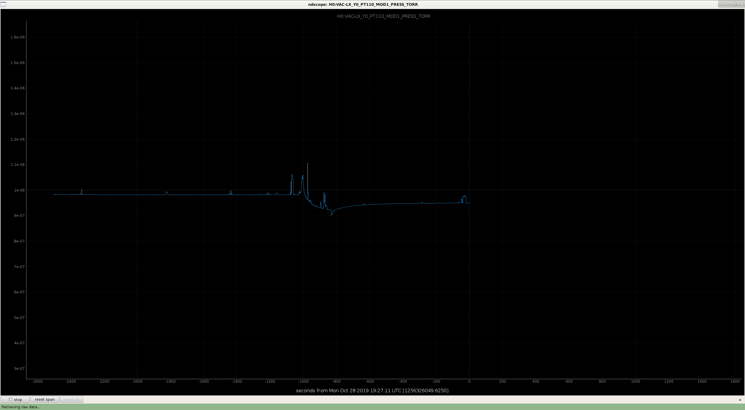
Richard, Patrick Command run around 19:12 UTC. Pressure plot attached.
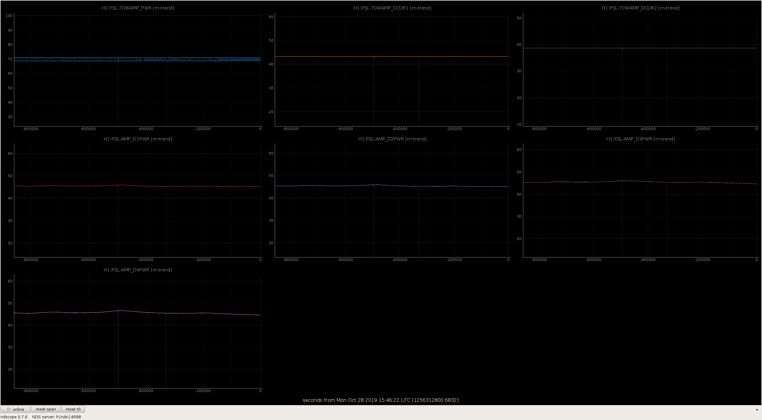
Laser Status:
Front End Power is 32.22W (should be around 30 W)
70W Output Power is 70.23W
Front End Watch is GREEN
70W Watch is GREEN
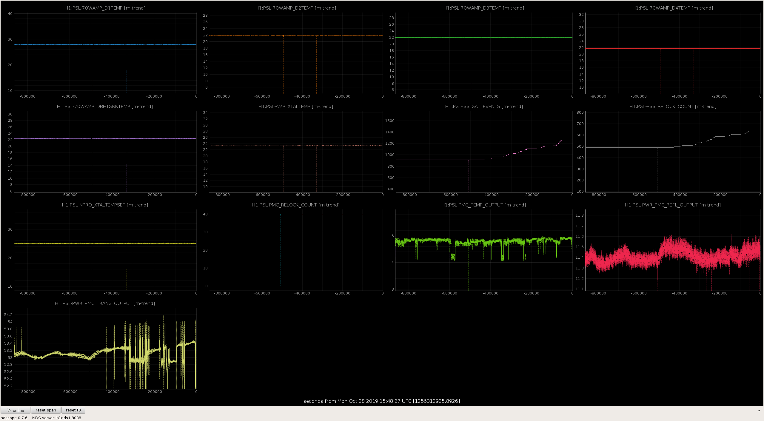
PMC:
It has been locked 10 days, 19 hr 18 minutes (should be days/weeks)
Reflected power = 11.46Watts
Transmitted power = 53.39Watts
PowerSum = 64.85Watts.
FSS:
It has been locked for 0 days 0 hr and 17 min (should be days/weeks)
TPD[V] = 4.846V (min 0.9V)
ISS:
The diffracted power is around 1.5%
Last saturation event was 0 days 0 hours and 17 minutes ago (should be days/weeks)
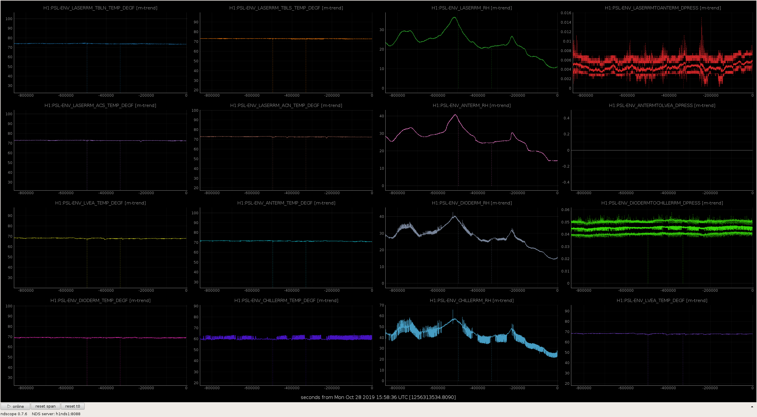
Possible Issues:
SudarshanK, DriptaB, JoeB, ShivarajK, RickS
We updated the ETMX and ETMY parameters file to include the updated O3 masses as outlined in the LHO alog 49398.
svn/sus/trunk/QUAD/Common/MatlabTools/QuadModel_Production/h1etmx.m
svn/sus/trunk/QUAD/Common/MatlabTools/QuadModel_Production/h1etmy.m
These files have been committed to the svn and the updated values are shown below:
For ETMX:
ear_mass_total = 0.044; % sum of both ears, from Betsy
ear_distance = 0.164; % D080658
amd_mass = .00205; % New AMD masses added to the test mass; Updated by S. Karki LHO alog # 49398
pend.m3 = 39.611+ear_mass_total+amd_mass; % 39.657 = 39.603 + ear_mass_total+amd_mass; Updated on 25 Oct 2019 by S. Karki, LHO alog # 49398
For ETMY:
ear_mass_total = 0.044; % sum of both ears, from Betsy
ear_distance = 0.164; % D080658
amd_mass = 0.00205; % amd mass added by S.Karki as per LHO alog 49398
pend.m3 = 39.538 + ear_mass_total+amd_mass; % 39.584 = 39.538 + ear_mass_total+amd_mass; Updated on 25th october 2019 by S. Karki as per the LHO alog # 49398
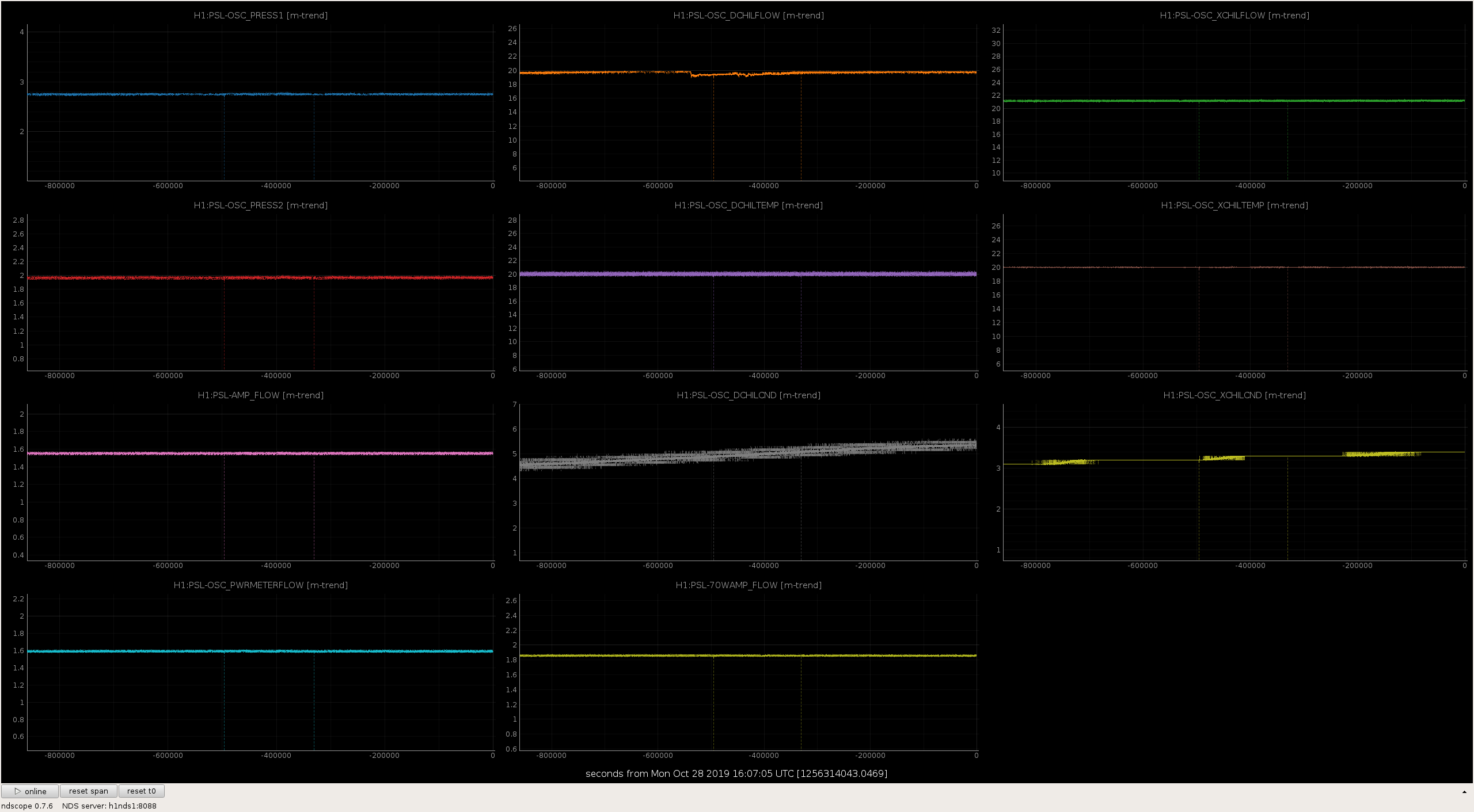
TCS-X chiller was full so added no water. TCS-Y was down 0.5 from 10.0 to 9.5. I added 50ml water to TCS-Y. Observed nothing out of the norm on both chillers. Closing FAMIS #11515.
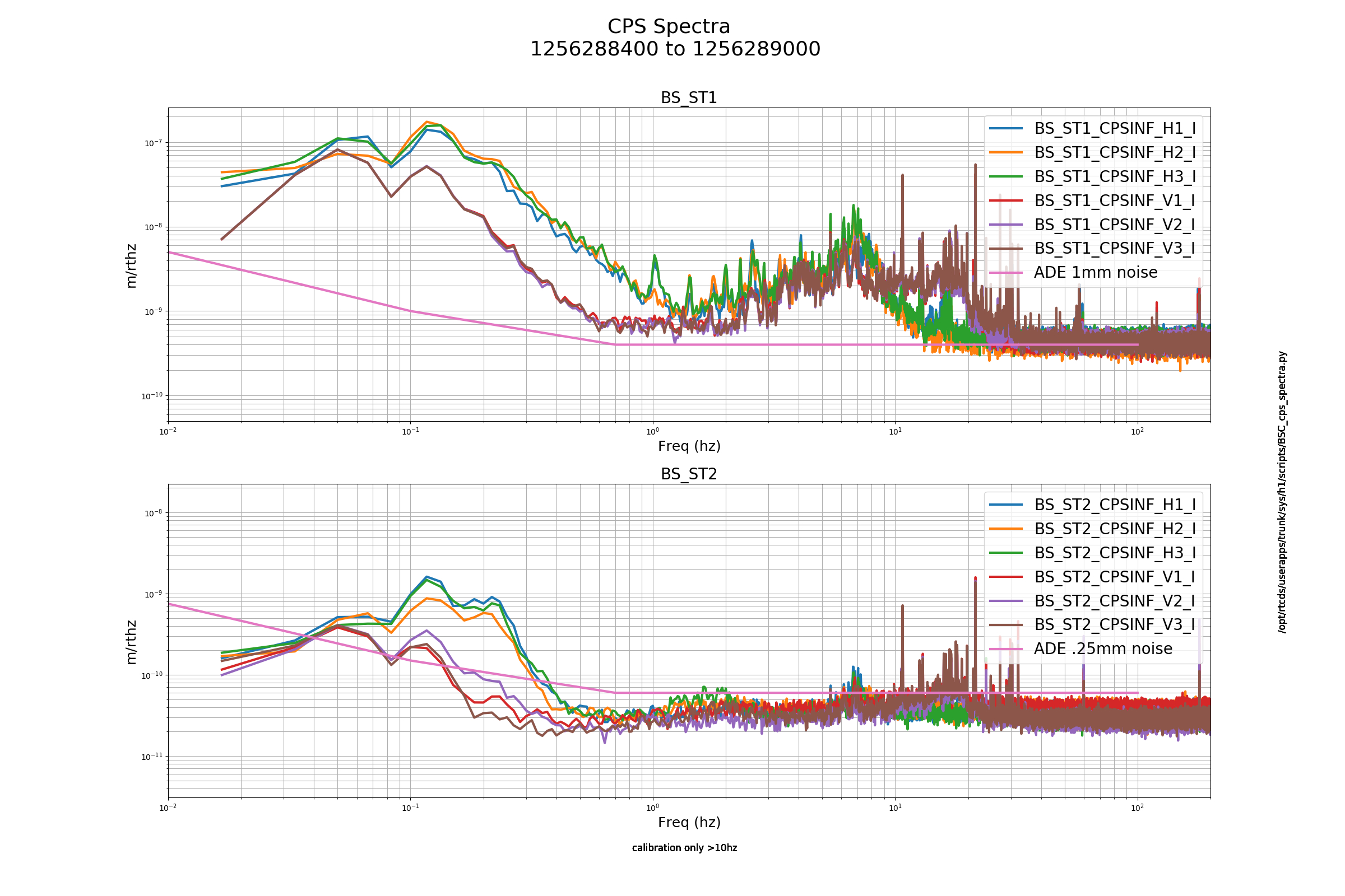
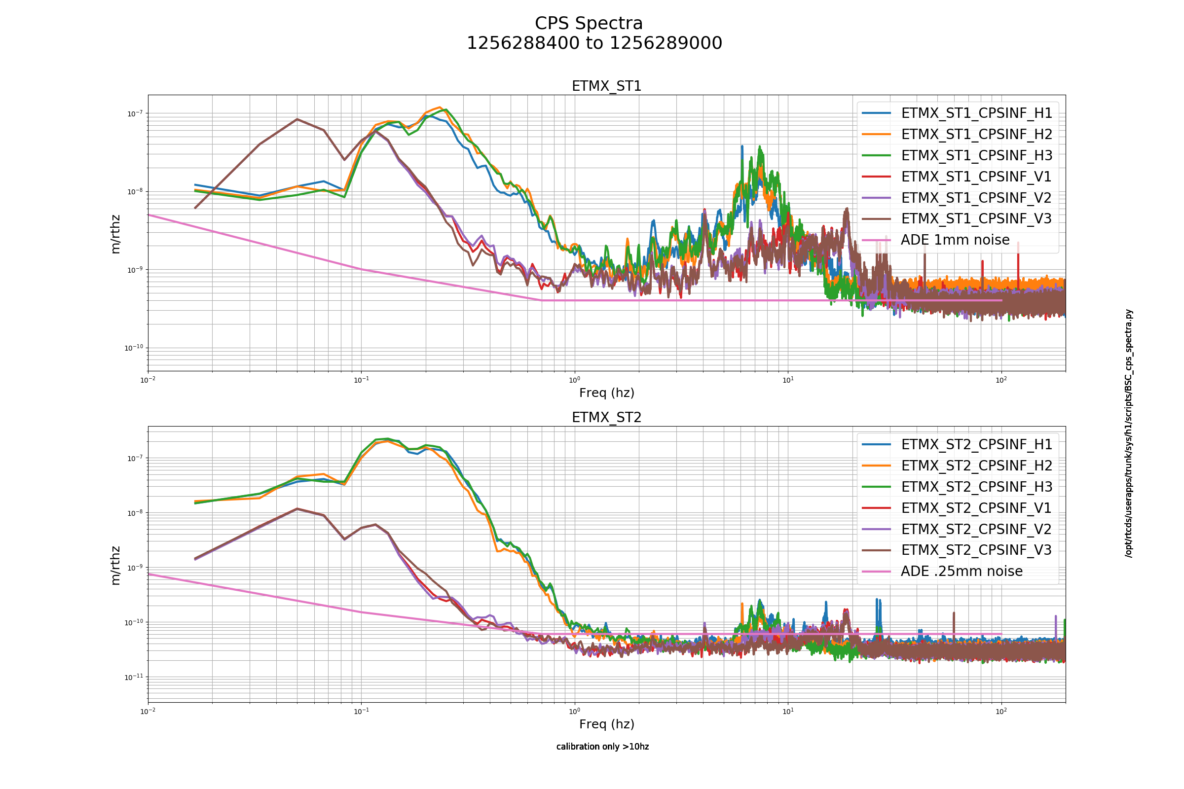
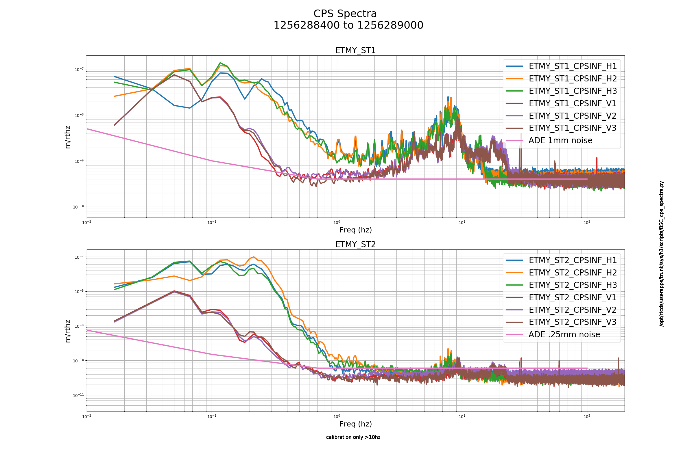
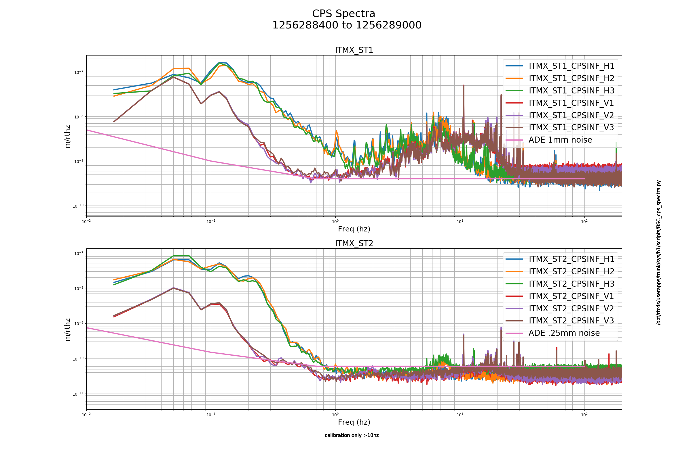
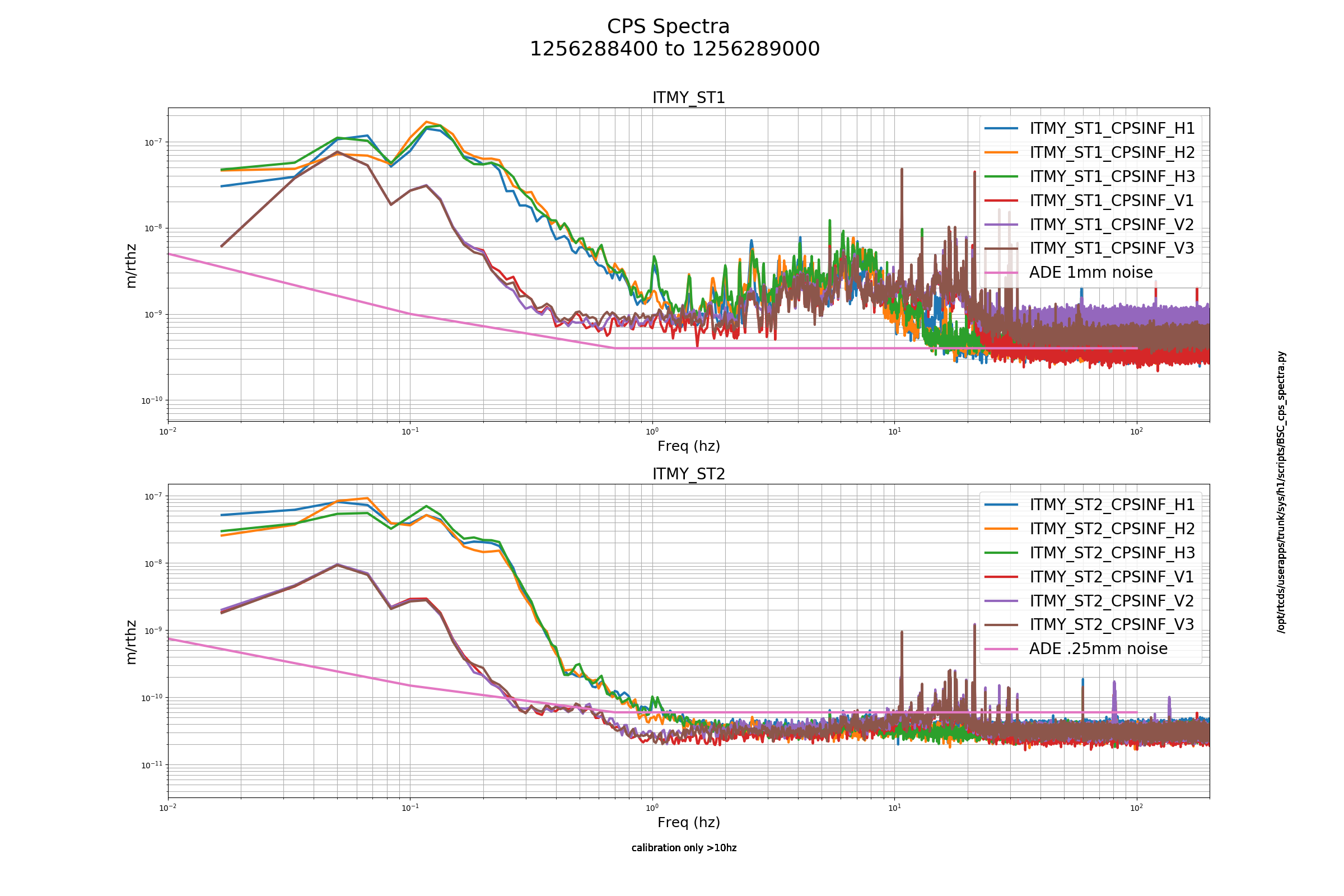
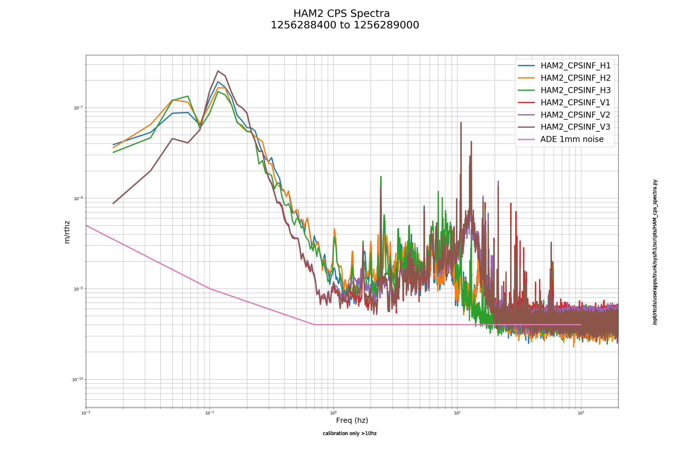
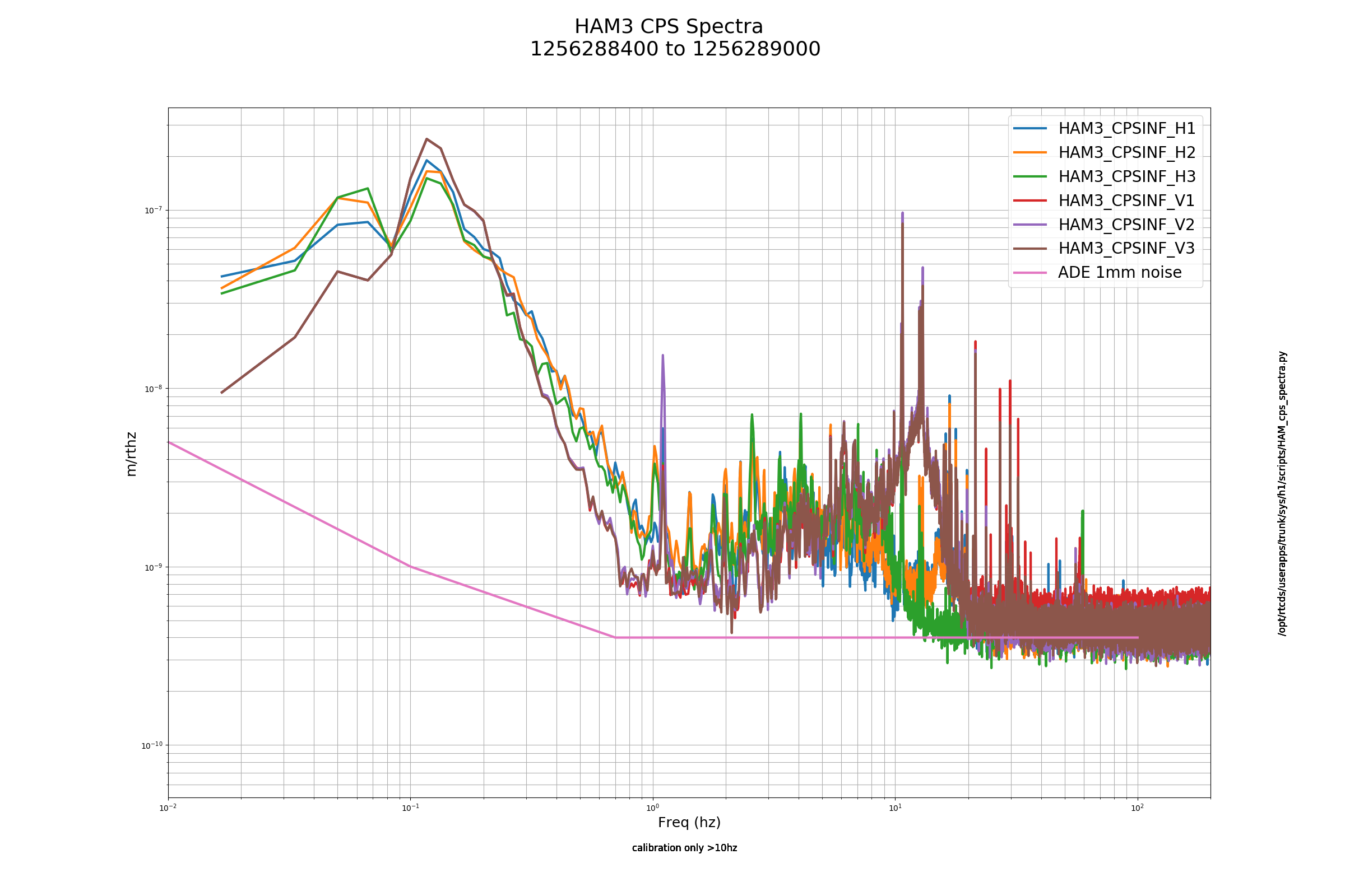
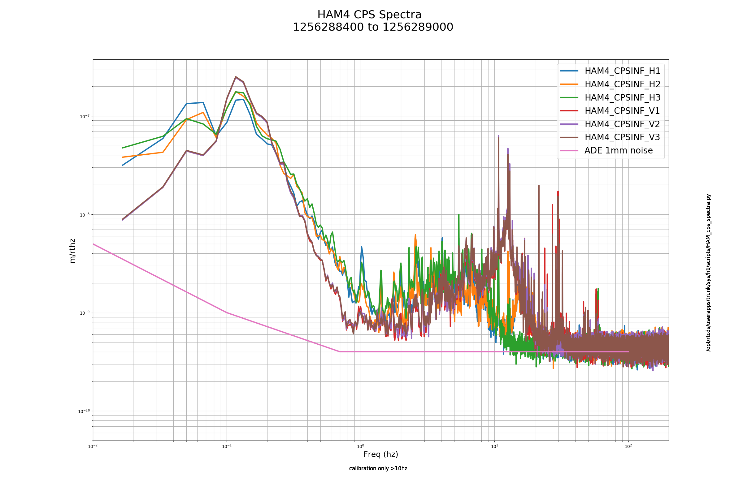
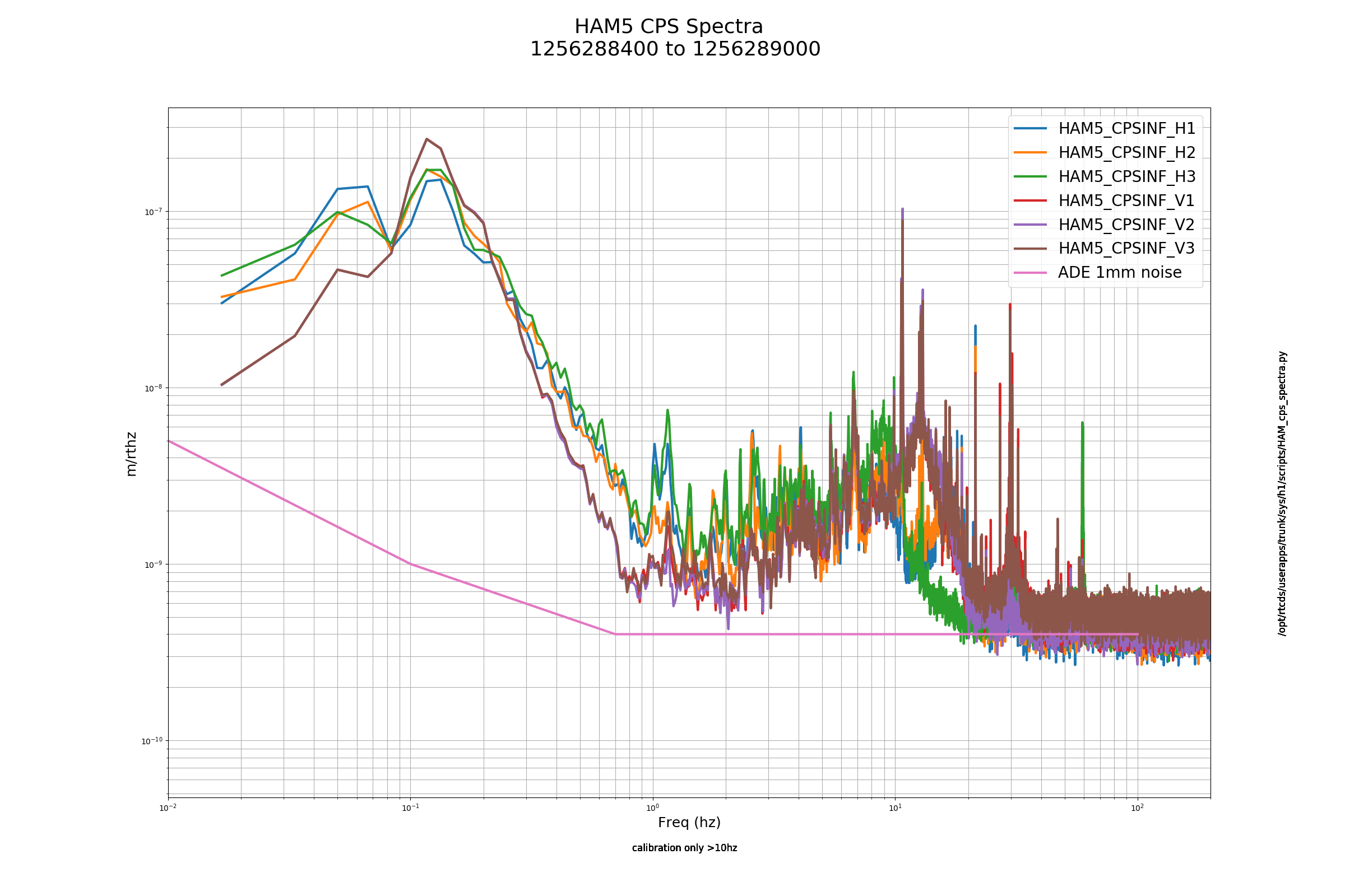
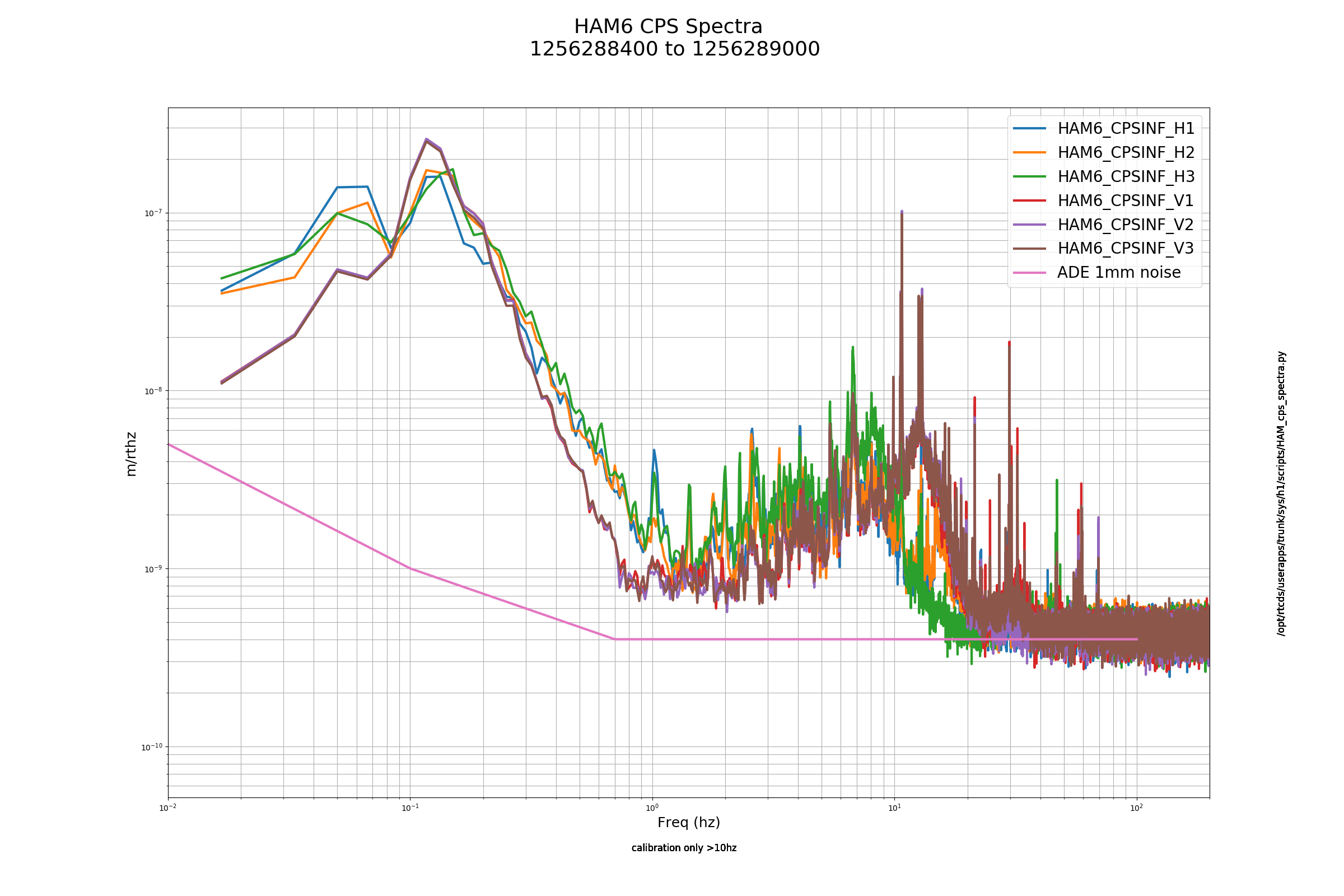
HAM5_CP_SINF_V2 is showing a fairly large spike in the 600 Hz area. Beside that the spectra look fairly similar to one another.
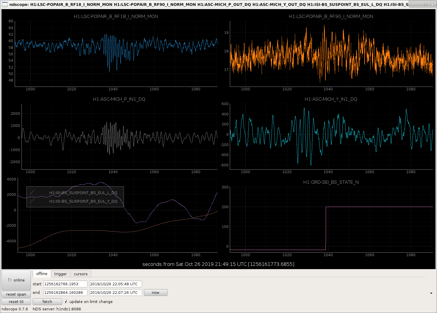
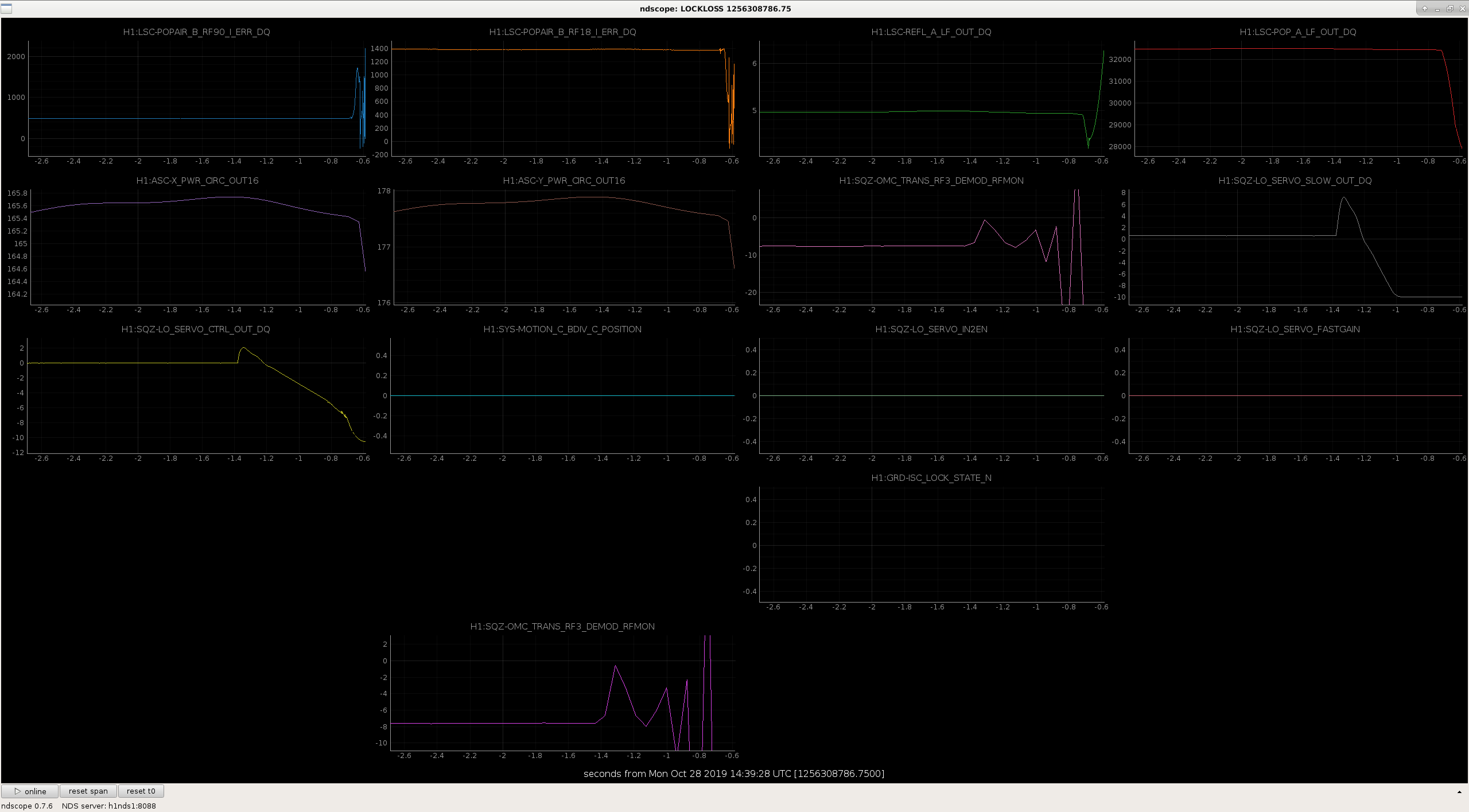
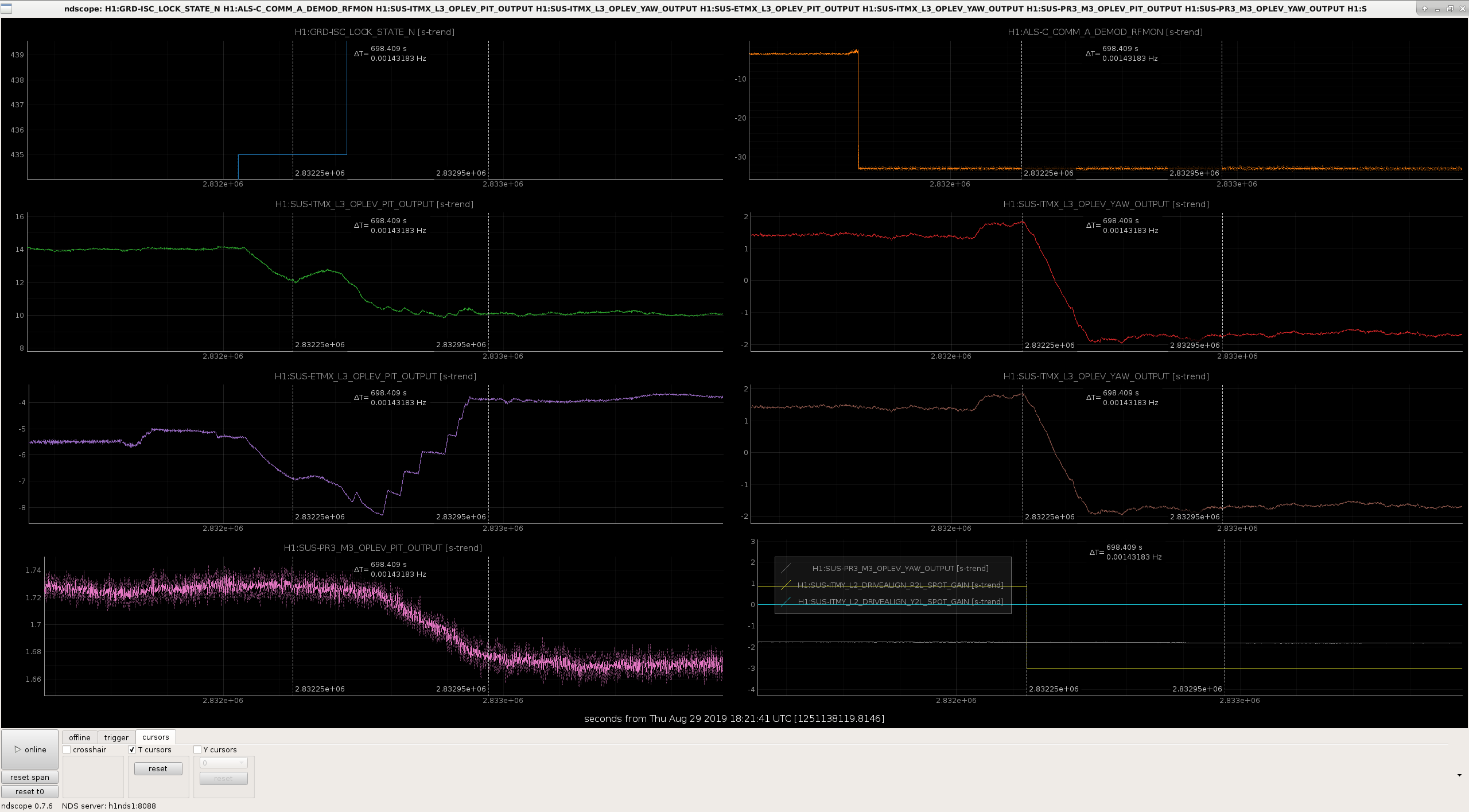
There are frequently times when the build ups and ASC signals in DRMI become verry noisy about 1 minute after it locks. The guardian does several things at the same time here, engages the DRMI ASC and waits for it to converge before offloading, requests BS stage 2 isolation, and changes DRMI from 1F to 3F locking. Today we went through these steps slowly to try to understand which of these steps causes the big kick, and it seems that the BS ST2 isolation loops are the problem. The attached screenshot shows that the problem happened durring the BS ST2 transition (there was not anything else going on at the time) although nothing seems to show up in the GS13 signals.
We are often able to ride this out, but we sometimes loose lock due to this. Looking at the lockloss tool summary plot that Niko posted in the second attachment to 52514, this is probably responsible for the cluster of locklosses between the states 105 (TURN_ON_BS_ST2) and 111 (offload DRMI ASC) which is about 100 locklosses in O3a.
Edit: In another locking attempt we waited again for the BS isolation loops, saw the big glitch but survived, then lostlock during the ASC offload, so there might be multiple problems in these states. For now I've set ISC_LOCK to wait for the BS to finish isolating ST2 before it moves on to the other DRMI things, so that it will be easier to tell why we are loosing lock.
Also, watching the isolation loops, the glitch seems to happen at the time when FM1 is switched off and FM8 is switched on for the horizontal loops. (second attached screenshot.)
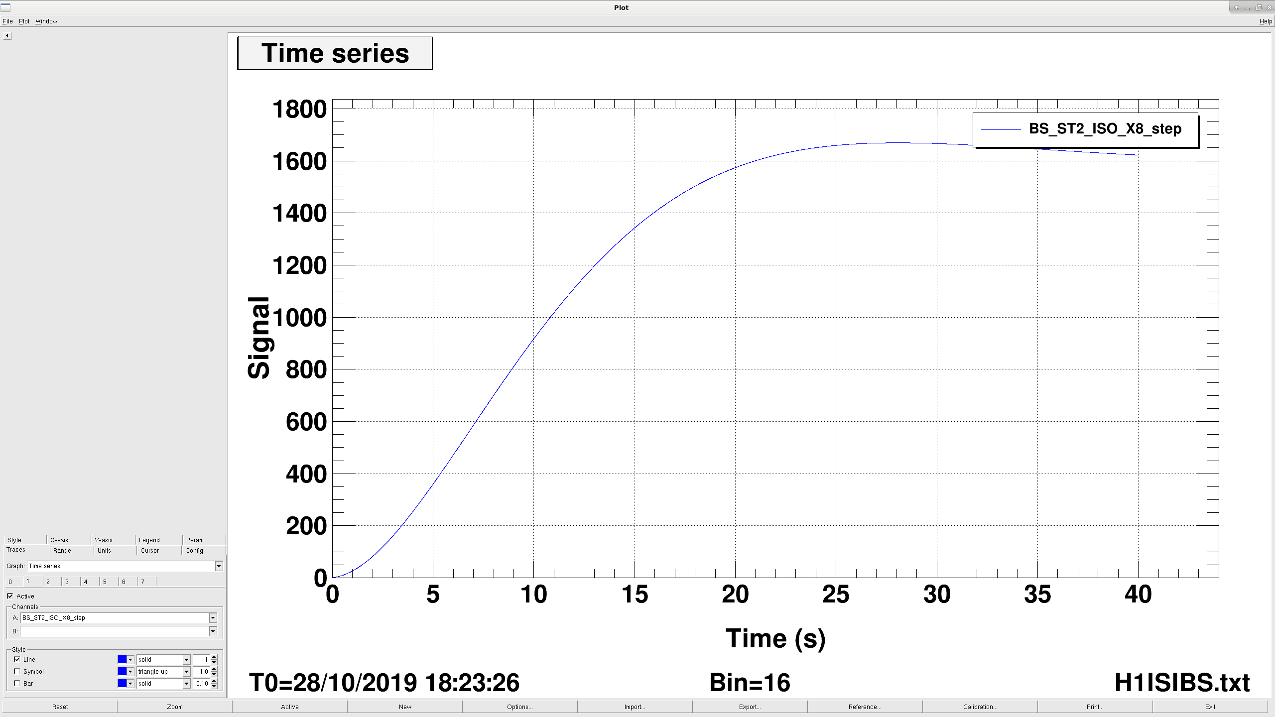
The filter being engaged when the glitch happens is a dc boost. It is a pair of poles at .05hz and a pair of zeros at 2hz. It's engaged with a ramp time of 5 seconds, but the filter has a step reponse of something like 10 seconds (first plot is the foton step response for this filter).
There are two things we could try to reduce the wiggle cause by engaging the boost: we could reduce the ramp time on the boost (maybe something like 1-2 seconds? That makes me a bit nervouse) or we could push the poles down to something like .02hz to slow down the step response. This shouldn't affect the stability of the controls.Second attached plot is the step response of a boost with .025 hz poles. This takes about twice as long to get to the same point.
Third plot is bode plot comparing the old filter in red and the new in blue. I adjusted the zeros so the DC gain was roughly the same. We lose gain between .1 and 1 hz, but most of the ISI performance comes from St1 anyway, which is unaffected. The BS already has lower gain St2 loops compared to the other ISIs, and we use to run with the St2 loops off, so maybe it's not a big deal.
I tweaked the St2 boosts on the BS ISI more or less as proposed, and seems like it's better. I pushed the poles down to .025hz and decreased the ramp time to 3 seconds.
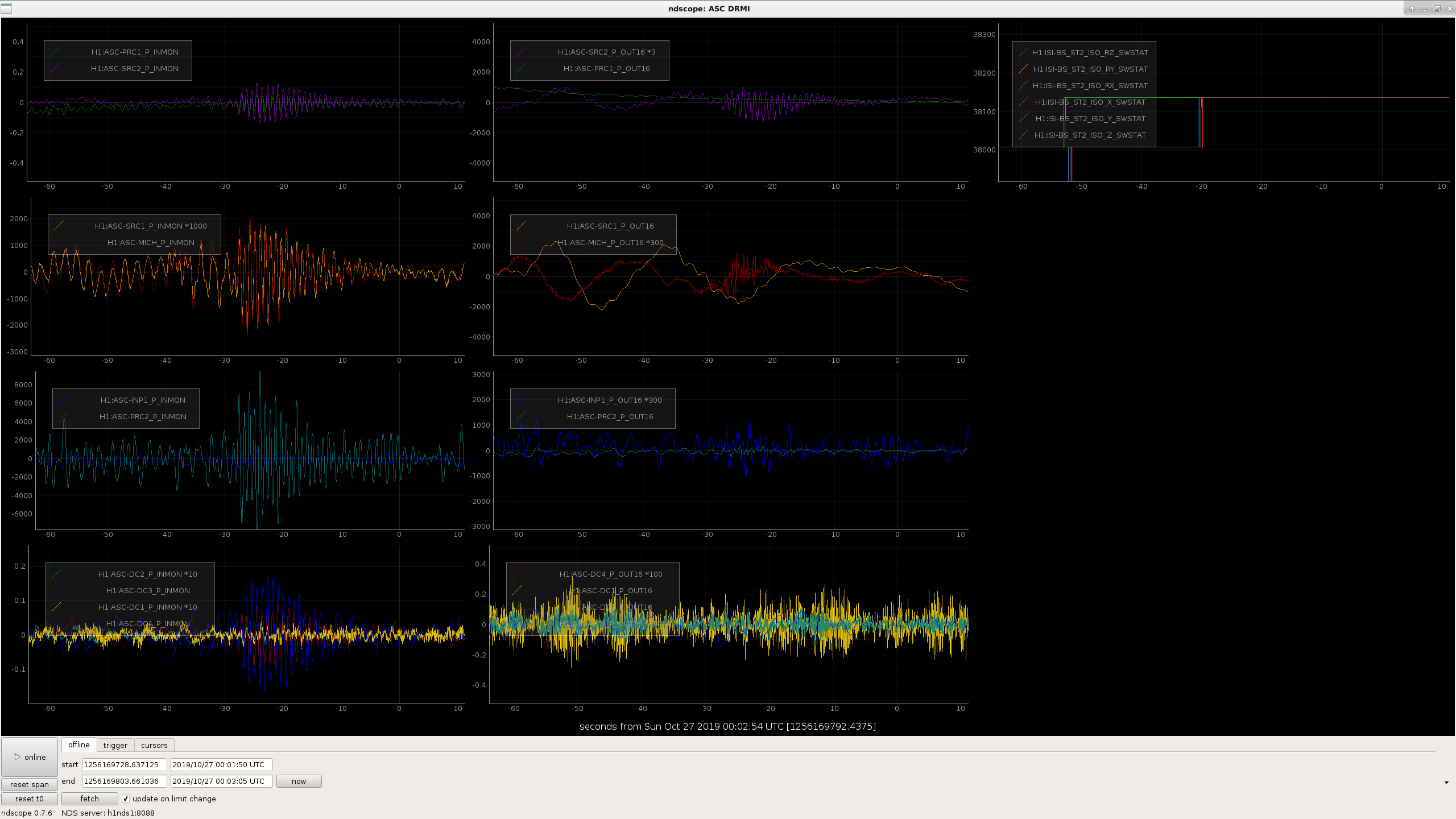
First attached screenshot are the POPAIR_B_RF18 and MICH_P asc from the BS turning on the ST2 loops just a couple minutes ago, second plot are the same trends from the glitch Sheila posted from the 26th. The glitch is about half as big on POP with the new filter settings. I'll check on this again after a couple more locks, but seems like this is a good change.