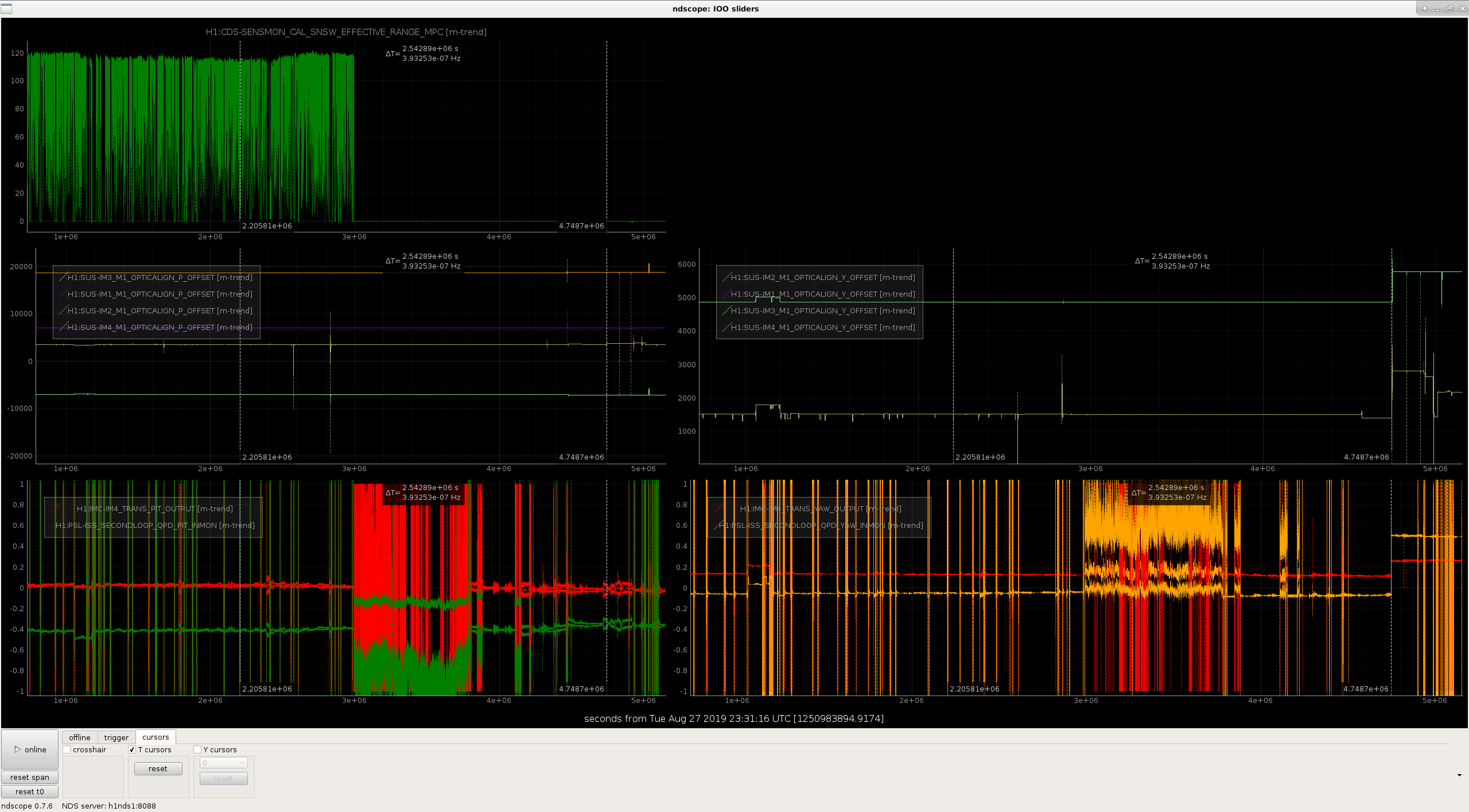
The h1susex models stopped running at 13:45 UTC (06:45 PDT) this morning (Sunday 27 Oct). This is a repeat of the last week's problem, in which h1susex appears to have lost an 18bit DAC (1-7 in that case, which was replaced with a spare).
I've stored all the system and Dolphin logs.
Looking at the PCI bus scan, there is a strange double entry for the 1-7 slot. Perhaps a board fault on this slot since this there is a new 18bit DAC card located there now?
Remember that even after replacing the suspect 18bit DAC, we got an 18bitDAC error on the first time the IOP model was started. I tested the DAC which was removed from h1susex on the DTS and it was not seen on the bus, suggesting it really was damaged.
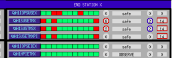
Here is the alog from Wednesday afternoon when we replace the 1-7 18bitDAC on h1susex alog52664
FRS13748 had been opened Wednesday to cover the h1susex 18bitDAC issue, I'm adding today's details to it.
Richard and I have discuss this problem on the phone, we are going to avoid using slot 1-7 and we hope the DAC card currently in that slot is still good, if not we will use a second spare. I'm planning how to reshuffled the cards to avoid this slot with the minimum disruption in the ribbon cabling.
Richard is on site. We have a card shuffle plan, h1susex is powered down, Richard is making the change to the chassis initially relocating the current 18bitDAC card which was in slot 1-7.
Referencing the IO Chassis layout shown above (it is slightly out-of-date, there is a second ADC in slot 1-8 and the 18bit DAC in slot 2-5 is now a 20bit DAC)
We are:
This leaves the suspect slot 1-7 empty, using 1-2 instead. DACs in 2-x slots are unaffected.
Bad news, the 18bit DAC which was in slot 1-7, now relocated to 1-2 is not seen on the bus, presumably it has been damaged (will test on DTS tomorrow). Richard is now installing a spare 18bit DAC into slot 1-2.
suggests slot 1-7 damages cards installed in it.
Spare 18bit DAC in slot 1-2 is seen, we have a full compliment of cards.
As a sanity check that we have the correct DACs wired, I'm going to run the Duotone DAC-ADC loopback.
BTW, h1iopsusex came back with a negative IRIG-B error, should clear in a few minutes.
h1susauxex had a timing glitch while we were working on h1susex's IO Chassis. I restarted the models and it is good now.
IRIG-B timing is good again. I did a quick DAC duotone loopback test (last channel of first DAC outputs the duotone signal, which instead of going out to the field is looped back to the second to last channel of the first ADC). Timing value on IOP-TP MEDM showed a steady measurement of 70uS, which went back to a noise signal when I turned the DT test off.
Richard is damping SUS-EX and recovering SEI-EX from its watchdog trips.
Thank you Dave and Richard!
I have logged the latest h1susex dmesg. The IOP model is not reporting any issues, the AUTOCAL of the 18bit DACs and the 20bit DAC looks good.
It certainly looks like h1susex IO Chassis slot 1-7 is broken to the point that it damages cards. This will ultimately be resolved when we upgrade h1susex to the new IO Chassis, which presumably we could think about doing early if we have further problems with this IO Chassis (given the ease of running MTP fiber at the end station).
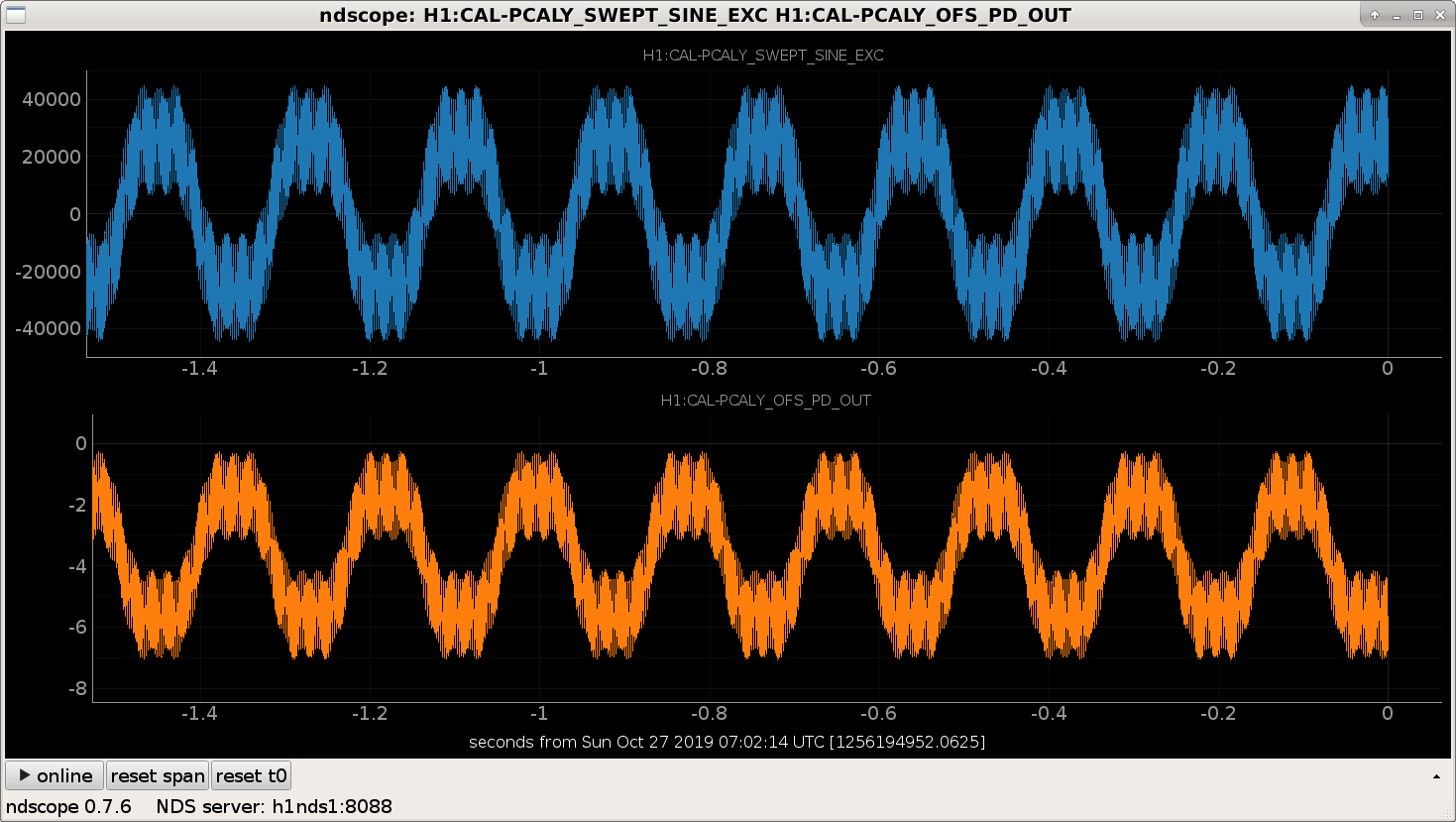
Now that we're back in low noise, I tried to inject multiple sine waves into DARM using the PCAL to get a sensing function measurement.
Using the result from alog 52526, I injected five sine waves spaced by factors of 3, starting with 5.62 Hz, to reduce the crest factor to avoid saturating the pcal.
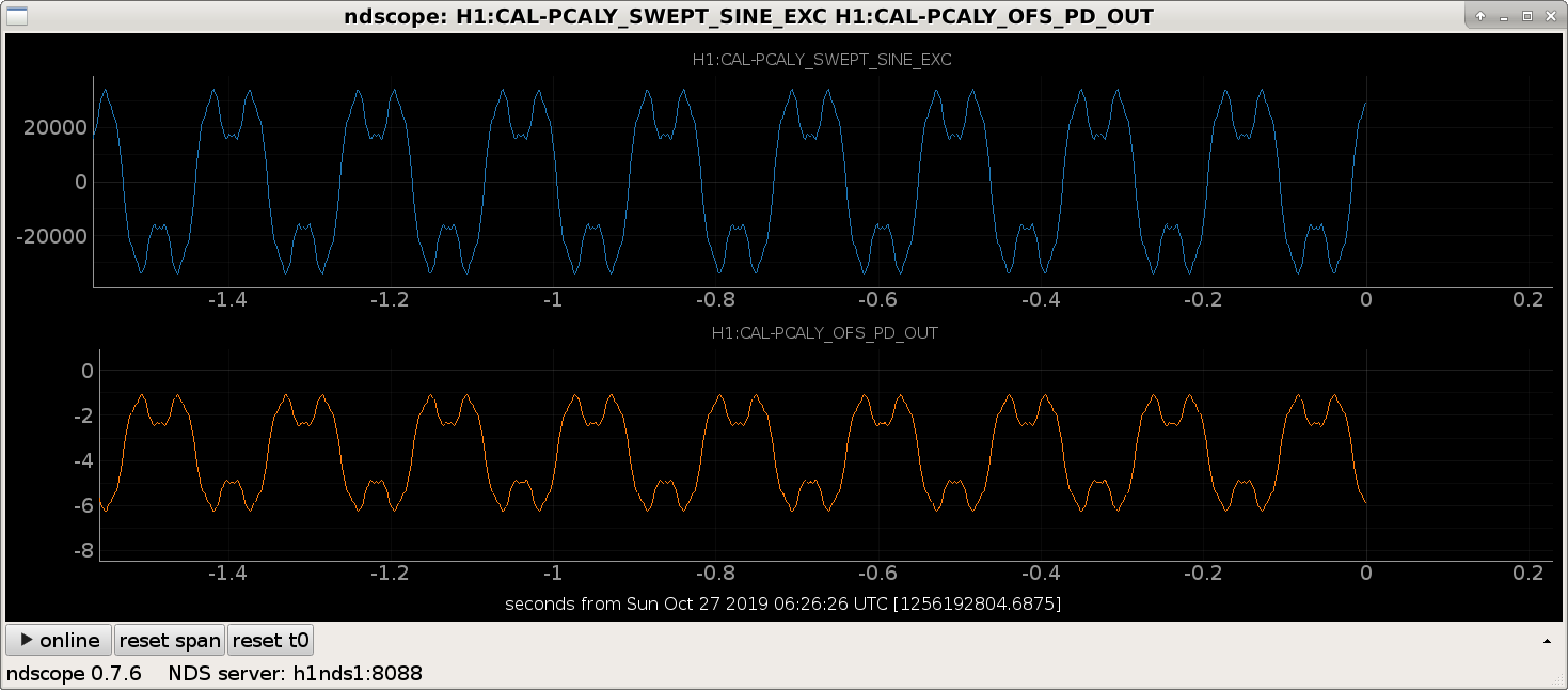
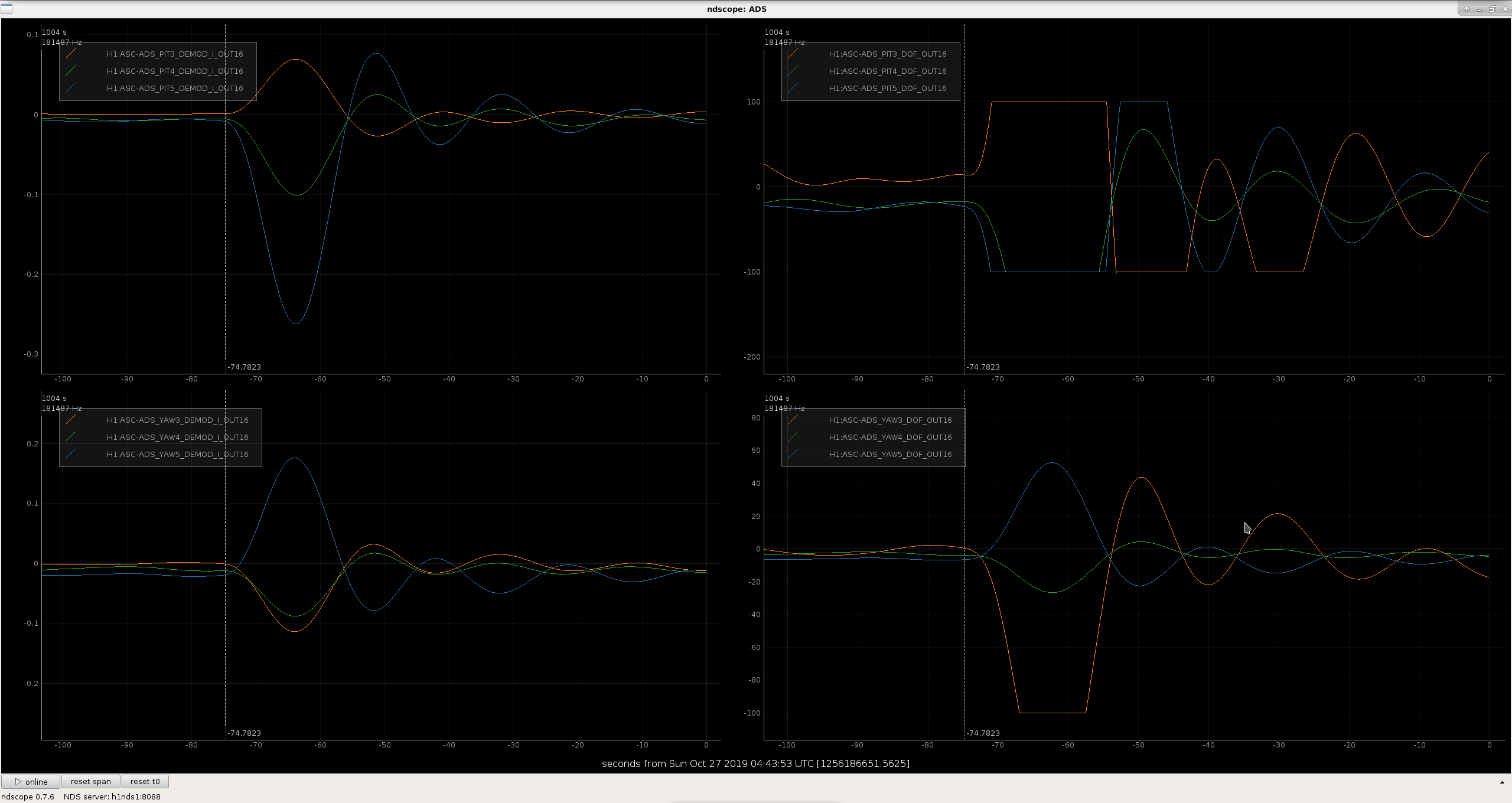
The pcal saturates when the laser is amplitude modulating its full 2 W, basically when the orange line in the ndscopes posted below hits 0 at some crest.
By injecting at factors of 3 in frequency spacing, and lowering the amplitudes of some of the injected lines to mirror the shape of DARM, I was able to get five going at once, with good coherence (PDFs attached).
The following should work in any CDS computer ipython terminal
import sys
sys.path.append('/ligo/home/craig.cahillane/Git/IFO/general/scripts/')
from dataUtils import *
freqs = np.array([ 5.62, 16.86, 50.58, 151.74, 455.22])
amps = np.array([30000., 5000., 2500., 573., 16511.])
phases = np.zeros_like(freqs)
offsets = np.zeros_like(freqs)
exc_channel = 'H1:CAL-PCALY_SWEPT_SINE_EXC'
my_inj = SineMultiple(exc_channel, amps, freqs, phases, offsets)
my_inj.start() # only run if you actually want to inject the sine waves!
my_inj.stop() # should ramp in 3 seconds
The cameras on IOT2L were not focused, and in the case of the REFL camera, the newly installed sutter prevents it from seeing the REFL sensor, so I moved that camera to look at the HWP/CW/2" steering mirror at the back of the table.
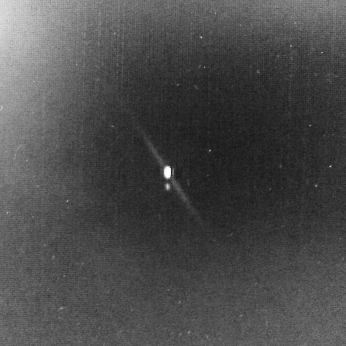
In looking at the WFS cameras, both are looking at WFS B, and there was clearly 2 beams when I focused, but our alignment was not set, so I revisitted this yesterday, and the two beams are still there. See attached pictures.
The source of the second beam is known, the design of the beam dump and pick off just before the beam splitter to the REFL PD are sensitive to alignment, and when the alignment changes enough, the beams that should be picked off or dumped make it through and polute the rest of the beam path. Attached is an annotated layout of IOT2L.
Unknown how long WFS has had 2 beams, but since we ended O3a, it's possible that PSL and MC1 changes could move the beam on IOT2L far enough to miss the beam dump and pick off. Attached are changes in the IMC since O3a, and MC1 in pitch is ~8urad, which is about 10mm at the REFL PD beam splitter, which is enough position change to move the unwanted beams off ot the beam dump and/or pickoff mirror. In the attachment, the beam changes are on the optics, MC1 and MC3.
Varun, Sheila, Georgia, Craig, Cao, Robert
Alignment:
Noise in DARM:
Once we had the ASC engaged, we had no difficulty wiith moving to the nominal state (other than the violin mode). However, we say very bad noise in DARM.
Other things today:
ADS limiters were added to limit the control signal when there's a huge glitch. This caused a lockloss at around 21 PDT today (Oct 26). Another large glitch happened just now, and the limiters worked, preventing a large deviation from nominal alignment.
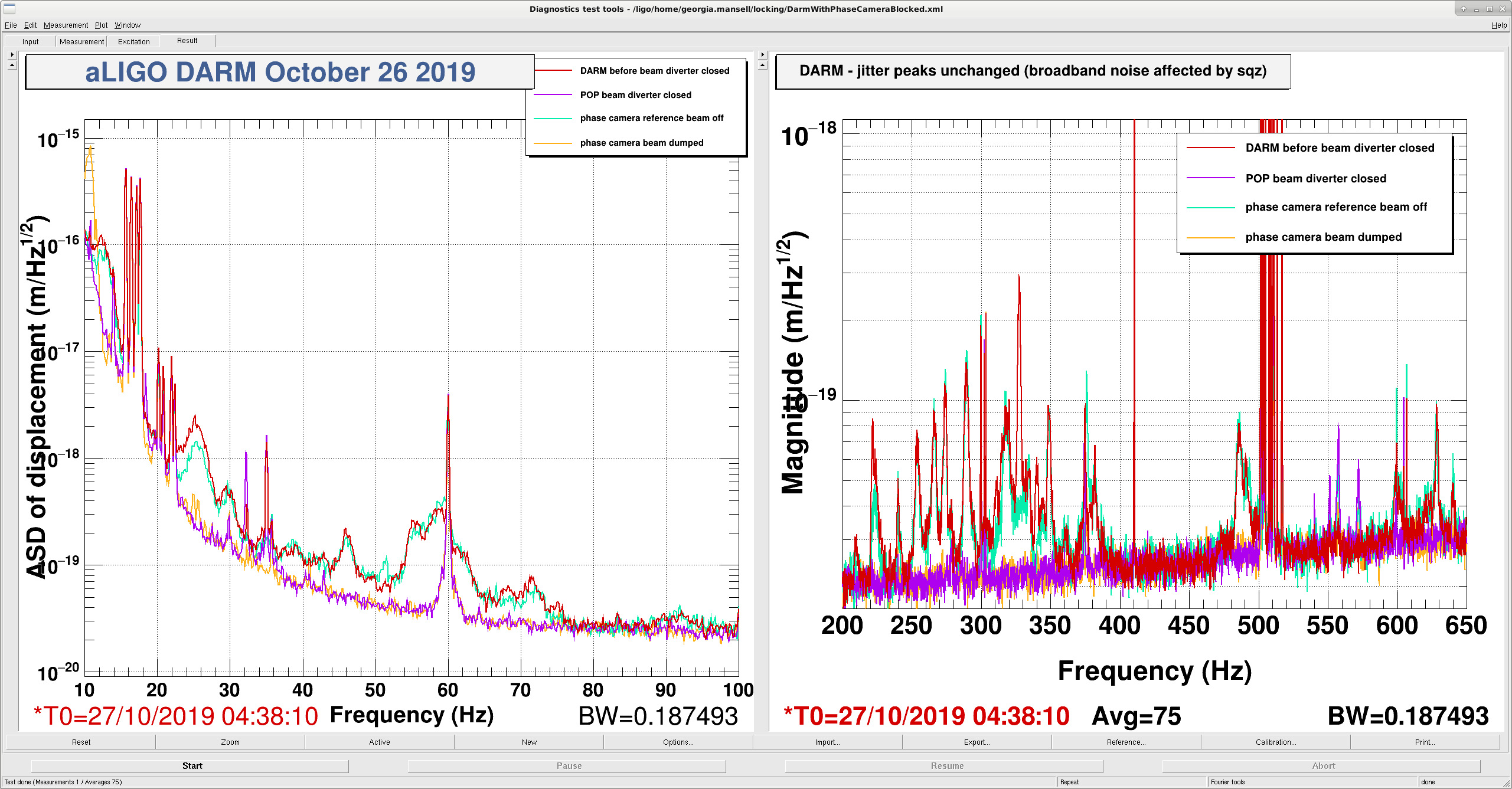
The excess noise in DARM was eliminated once the phase camera was blocked.
While the interferometer has been locked (and perhaps exacerbated while Cao and I were walking past HAMs 1 & 2) we have seen occaisional large scattering shelves which also show up in the auxiliary length degrees of freedom FOM, from 5Hz to 50Hz.
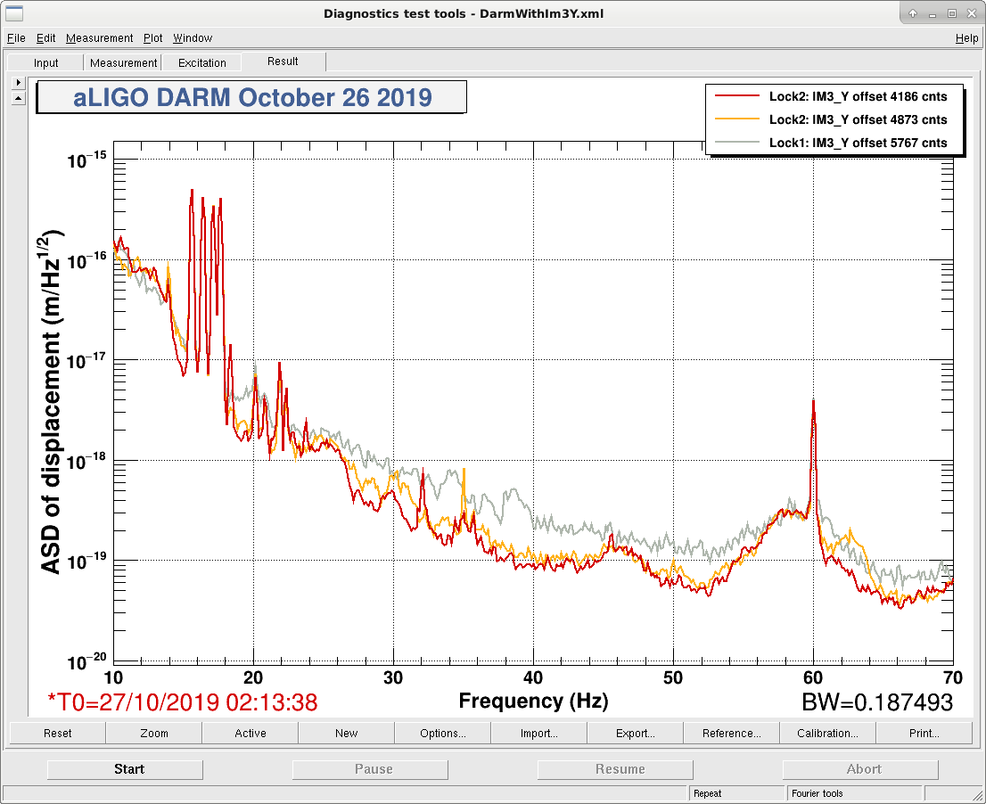
The low frequency DARM noise also changed with IM3 yaw alignment.
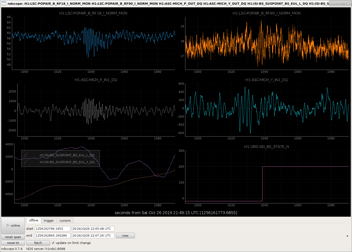
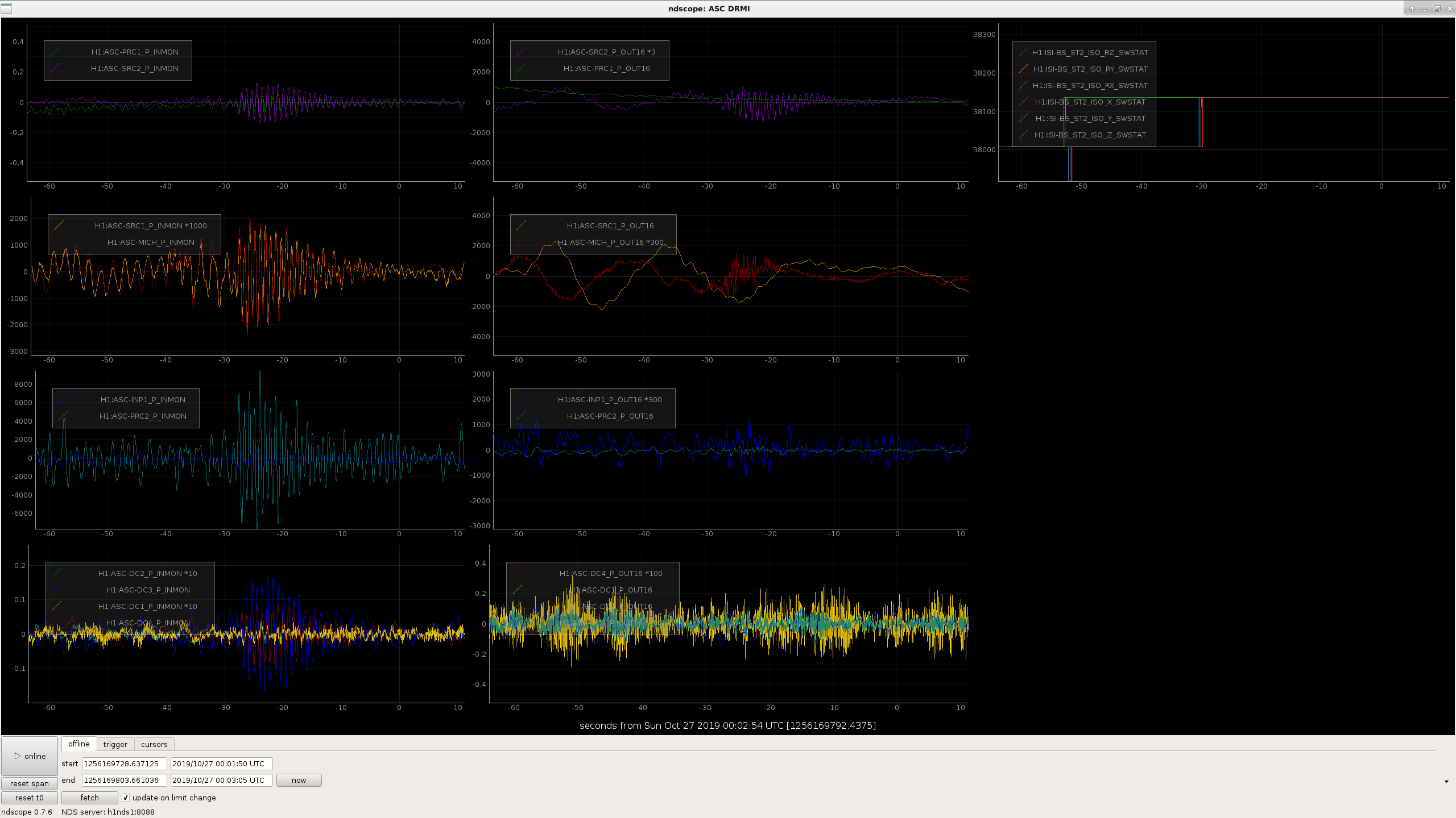
There are frequently times when the build ups and ASC signals in DRMI become verry noisy about 1 minute after it locks. The guardian does several things at the same time here, engages the DRMI ASC and waits for it to converge before offloading, requests BS stage 2 isolation, and changes DRMI from 1F to 3F locking. Today we went through these steps slowly to try to understand which of these steps causes the big kick, and it seems that the BS ST2 isolation loops are the problem. The attached screenshot shows that the problem happened durring the BS ST2 transition (there was not anything else going on at the time) although nothing seems to show up in the GS13 signals.
We are often able to ride this out, but we sometimes loose lock due to this. Looking at the lockloss tool summary plot that Niko posted in the second attachment to 52514, this is probably responsible for the cluster of locklosses between the states 105 (TURN_ON_BS_ST2) and 111 (offload DRMI ASC) which is about 100 locklosses in O3a.
Edit: In another locking attempt we waited again for the BS isolation loops, saw the big glitch but survived, then lostlock during the ASC offload, so there might be multiple problems in these states. For now I've set ISC_LOCK to wait for the BS to finish isolating ST2 before it moves on to the other DRMI things, so that it will be easier to tell why we are loosing lock.
Also, watching the isolation loops, the glitch seems to happen at the time when FM1 is switched off and FM8 is switched on for the horizontal loops. (second attached screenshot.)
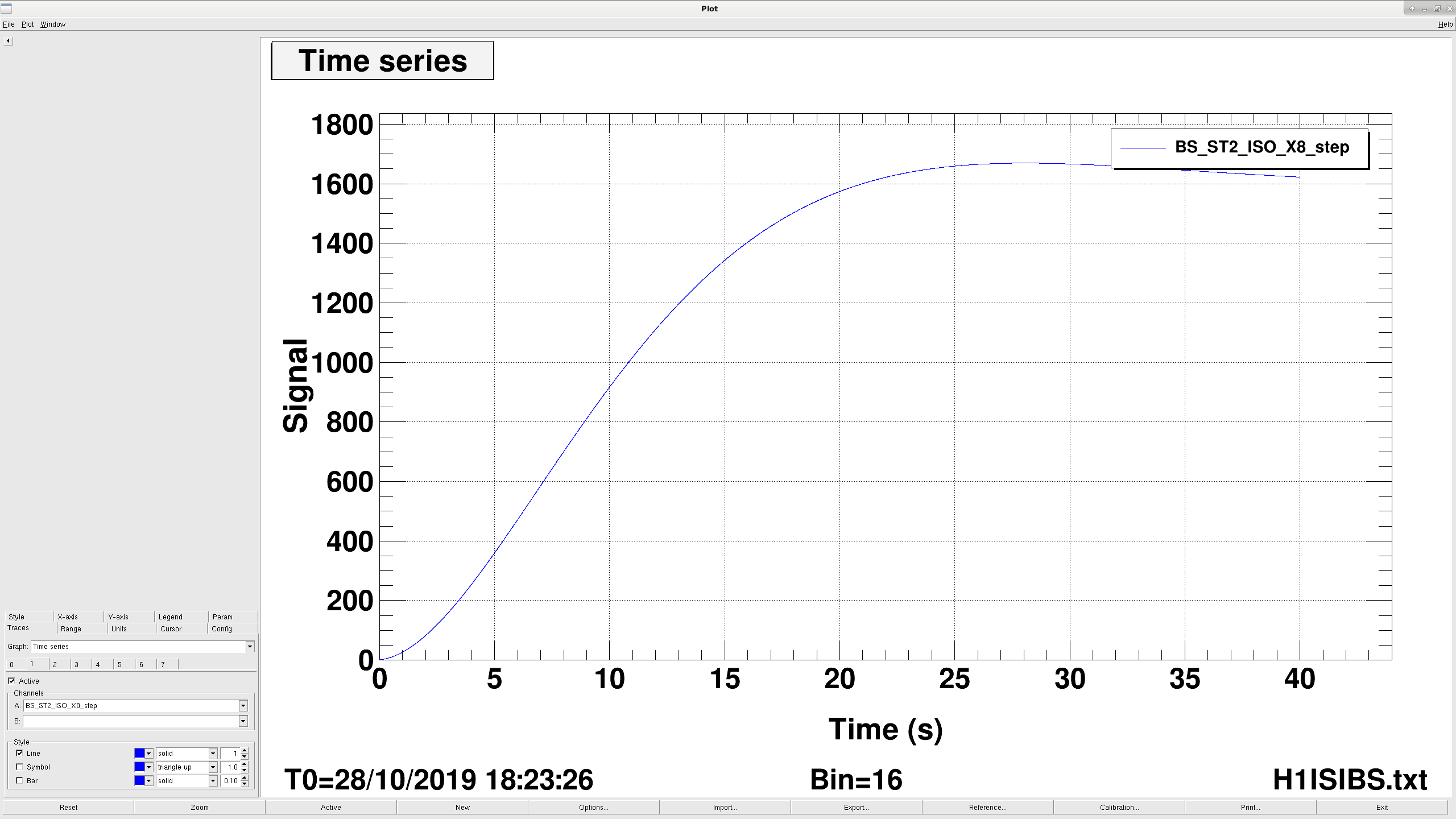
The filter being engaged when the glitch happens is a dc boost. It is a pair of poles at .05hz and a pair of zeros at 2hz. It's engaged with a ramp time of 5 seconds, but the filter has a step reponse of something like 10 seconds (first plot is the foton step response for this filter).
There are two things we could try to reduce the wiggle cause by engaging the boost: we could reduce the ramp time on the boost (maybe something like 1-2 seconds? That makes me a bit nervouse) or we could push the poles down to something like .02hz to slow down the step response. This shouldn't affect the stability of the controls.Second attached plot is the step response of a boost with .025 hz poles. This takes about twice as long to get to the same point.
Third plot is bode plot comparing the old filter in red and the new in blue. I adjusted the zeros so the DC gain was roughly the same. We lose gain between .1 and 1 hz, but most of the ISI performance comes from St1 anyway, which is unaffected. The BS already has lower gain St2 loops compared to the other ISIs, and we use to run with the St2 loops off, so maybe it's not a big deal.
I tweaked the St2 boosts on the BS ISI more or less as proposed, and seems like it's better. I pushed the poles down to .025hz and decreased the ramp time to 3 seconds.
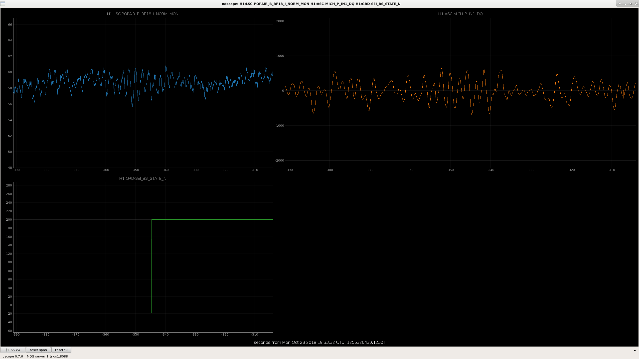
First attached screenshot are the POPAIR_B_RF18 and MICH_P asc from the BS turning on the ST2 loops just a couple minutes ago, second plot are the same trends from the glitch Sheila posted from the 26th. The glitch is about half as big on POP with the new filter settings. I'll check on this again after a couple more locks, but seems like this is a good change.
Lee, Kentaro, Sheila, Georgia
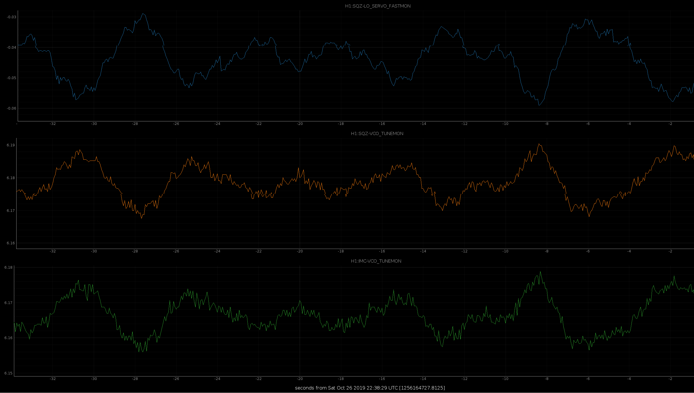
I've been tracking an regular glich that appears in the EOMRMSMON of the squeezer TTFSS. This glitch also corresponds to real phase noise seen in the beatnote between the seed and LO light on the homodyne. When the squeezer LO-loop is ON the glitch disappears.
SQZ_TTFSS_EOMRMS_Spikes.png shows the EOMRMSMMON channel while the LO loop is OFF. The glitch occurs near a voltage crossing of the PSL VCO. When the LO loop is enabled, the EOMRMS stays low, but you can see in SQZ_VCO_tunephase.png. That the SQZ VCO is tracking the PSL vco due to the LO loop. This was supposed to be prevented by the reconfiguration of the ALS fiber pickoff in 52381. Georgia helped us track the signals driving the ALS distribution AOM and it appears to be sourced by the PSL VCO OUT2 (split to also enter RF Patch Panel #11 on ISC-R1) rather than being sourced from a static REF 79.4MHz from the distribution source.
Currently, I think the squeezer is effectively still locked to the refcavity frequency, so we cannot easily measure seeding or backscatter, and the CARM-FF channel is needed until we reconfigure the ALS-distribution-AOM source.
I still do not understand the glitching though. It is appearing in the EOM monitor and doesn't correspond to any channels than the VCO frequency (not the PZT offset, slow offset or SQZ frequency counters). This suggests that it is a drifting whistle-like beatnote showing in the FSS PFD moving in and out of the control band and being driven into real phase noise by the servo (at a high enough frequency to be visible in the RMS monitor). While it is fortunate that it lessens when the LO loop is active, it is strange that it goes away only when the SQZ VCO moves with the PSL VCO. This suggests some underlying cause that could be injecting some phase noise through the TTFSS servo at other times, even if it is not so obvious as these glitches. We'll keep tracking it.
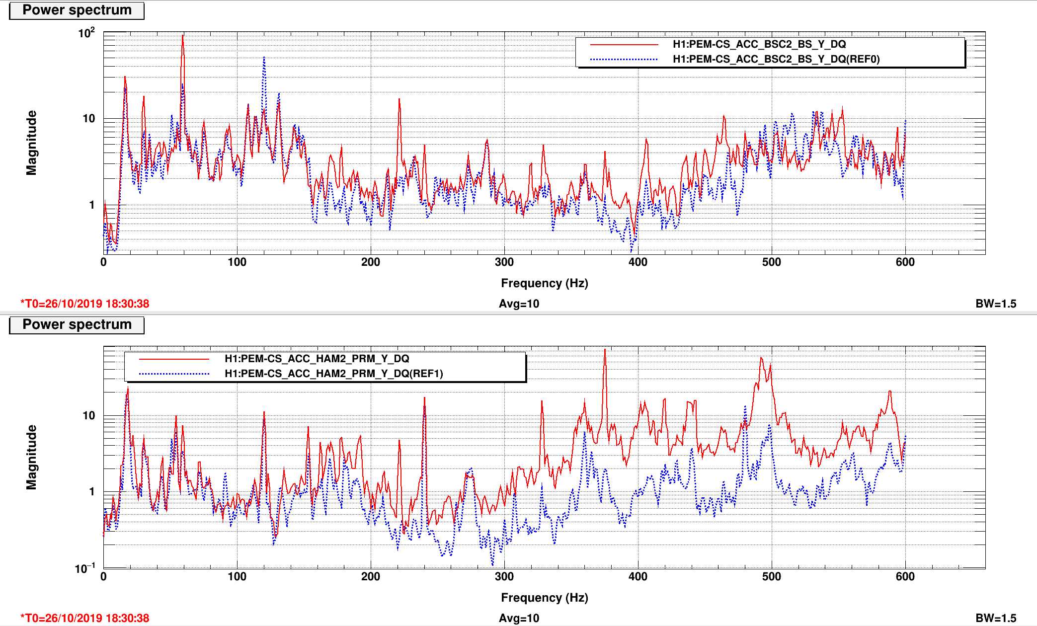
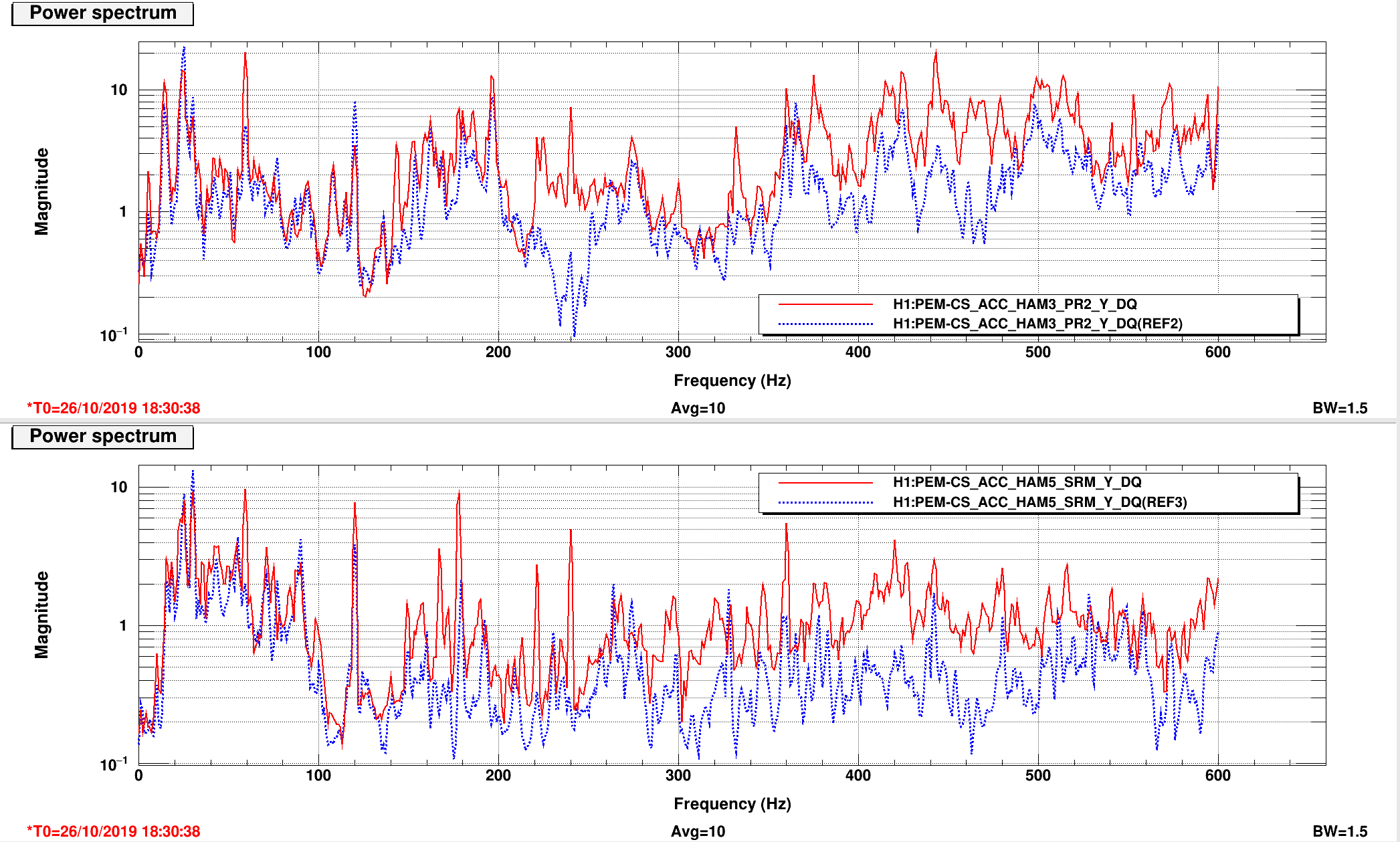
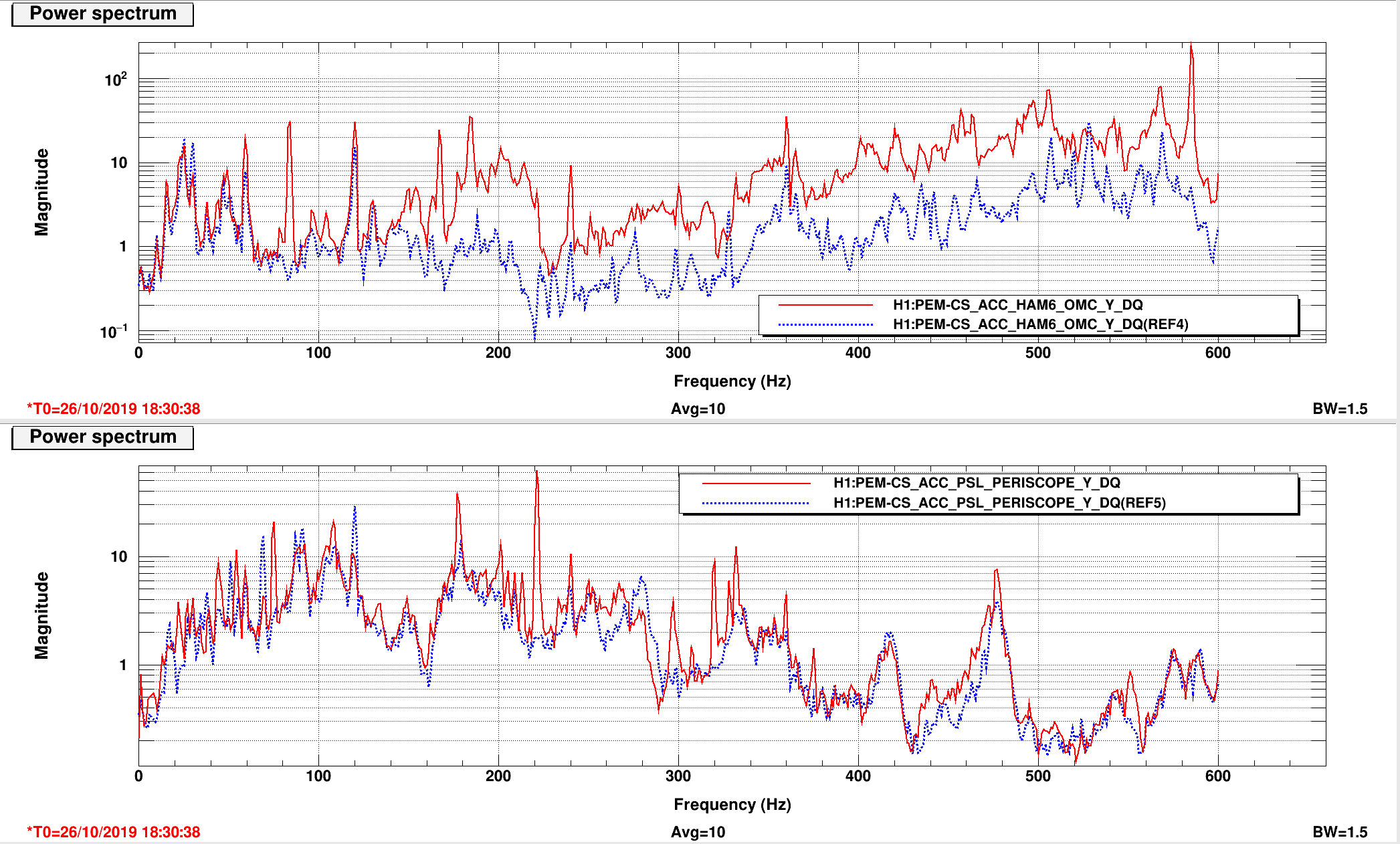
Sheila Varun After acquiring full lock in nominal noise we observe excess noise in frequencies band from 10 Hz to 600 Hz. Reading out the accelerometer at the different chambers during the full lock from this morning (red) and comparing it against Sep 21 2019 19:03:38 UTC (dashed blue), we observe almost a factor of 10 more noise as compared to late O3a. Please refer to the plots attached.
Robert came in and doesn't think that extra motion on the chamber walls can explain the excess noise we are seeing in DARM, so we are looking for some other explanations.
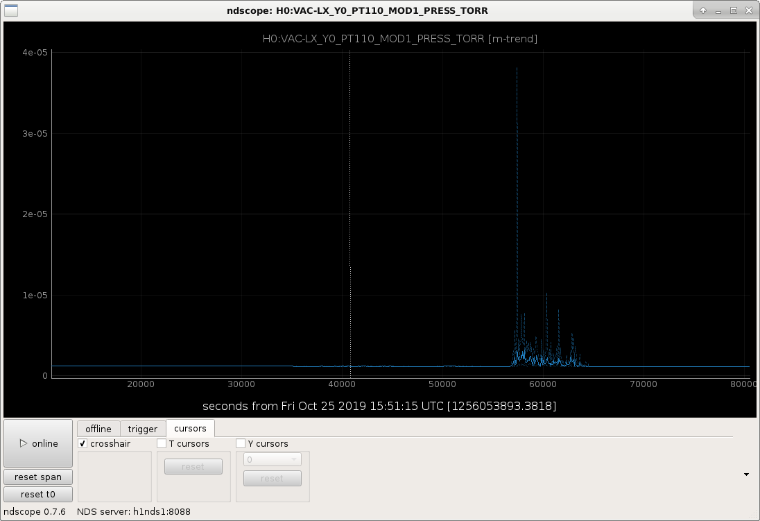
The HAM6 shutter doesn't have high voltage. (The medm screen says that the high votlage is OK, but the LED on the driver says the capactior is only charged to 13V.) With Varun as a phone buddy I went to the mezzanine, the HAM6 high voltage supply is off. Attached is a trend of PT-110 over night, there is a spike to 4e-5 Torr around midnight . It is reading 1.1e-6 Torr now.
Talked to Richard on the phone and reset the high voltage.
On second reading, this is another example of the HV tripping off due to the gauge noise spike observed earlier this week. As discussed then, we can swap-out the gauge electronics as the first step in a troubleshooting process.
Gerardo had suggested degassing the hot filament last week but I don't see a LOG entry recording this. This should be done before anything else. I think that Patrick T. can do this via CDS? Beckhoff?
Sheila Varun Cao TJ Dan B Jim Georgia Patrick Jenne
This morning we were able to get to resonance by changing some gains and offsets in the CARM offset reduction.
Seismic/ISis:
Oher locking:
Jenne, Chiara.
Today was very windy, so the locking team was not able to lock the interferometer, but it became much easier once the CPS DIFF was on. In this case the HAM2 and HAM3 were locked together and also BS, ITMX and ITMY were locked together.
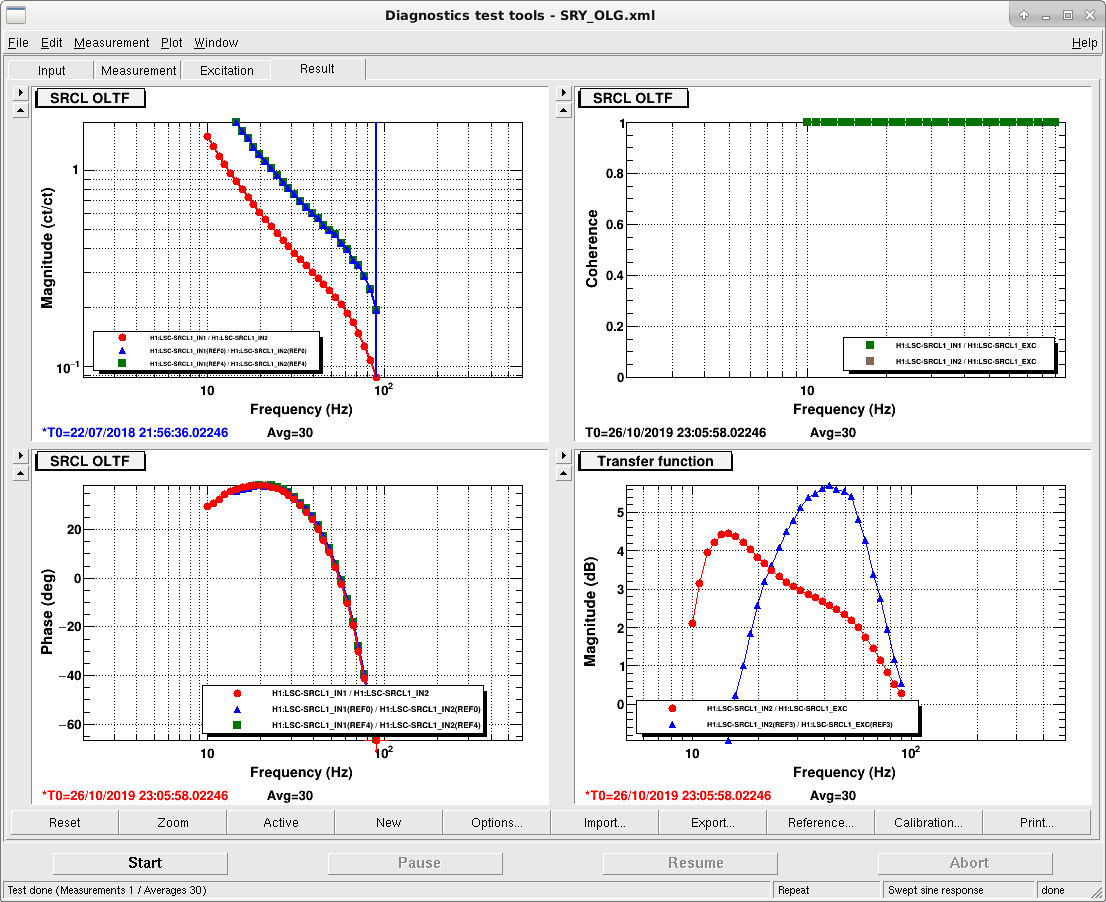
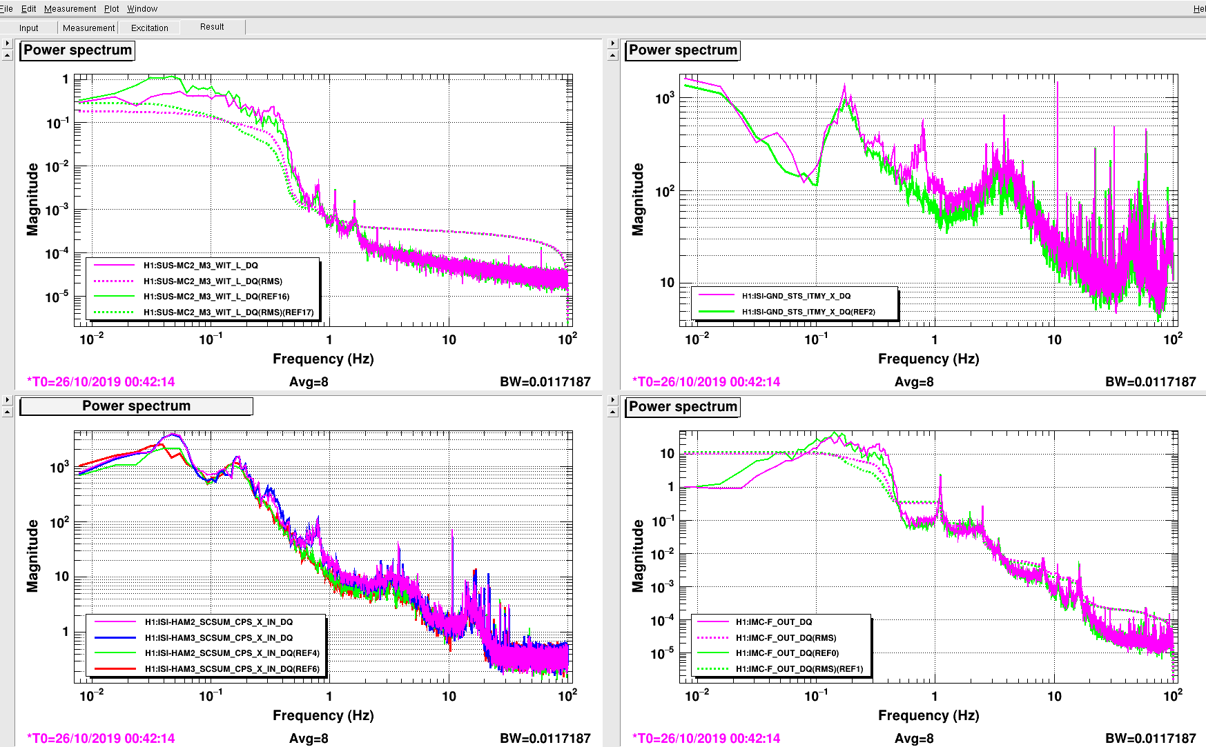
The plots in attachment show measurements in on (pink) and off (green) conditions of CPS DIFF; for HAM chambers plots, off traces are in green and red, on traces are in pink and blue. We got some data (MICH, PRCL, SRCL, DARM) when the system was on and the interferometer was at full resonance, but we can't get a reference of the system in off mode since we can't lock without it.
These results are similar to previous ones in earlier posts, we are showing that this can be helpful to reach the lock.
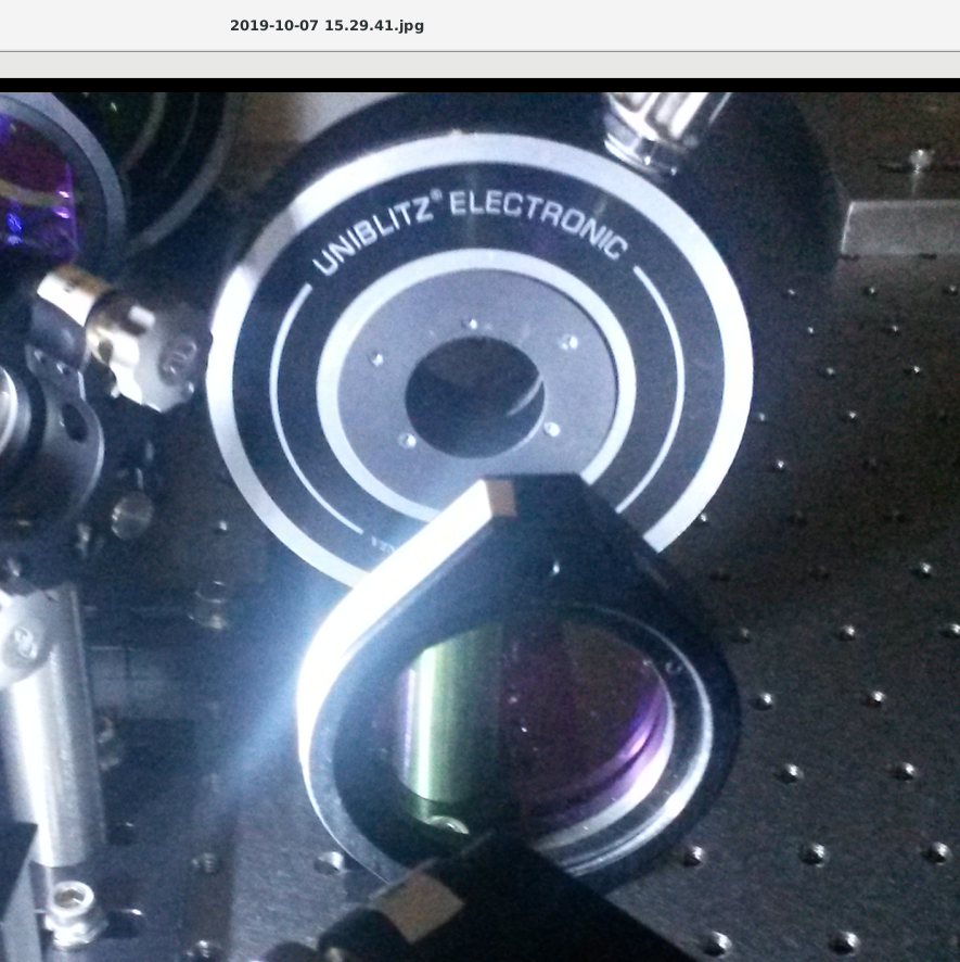
When looking at ISCT1 last week, I used a small flashlight to read some labels, and found particulate that might be a concern on the 2" lens, POP-L1. Image attached.
Jenne Driggers, Adrian Helmling-Cornell
Today we updated the photodiode used for the frontend lockloss trigger from POP_A_DC to POPAIR_A_DC, as it responds slightly faster to the interferometer losing lock. The lockloss trigger is armed when Guardian enters the OFFLOAD_DRMI_ASC state. As Guardian goes through the CARM offset reduction sequence, if POPAIR_A normalized by the laser power falls below 2.5 the lockloss trigger will now trigger, stopping actuation. When Guardian reaches and passes the DRMI_TO_POP state, the trigger triggers if POPAIR_A normalized by the laser power falls below 108.
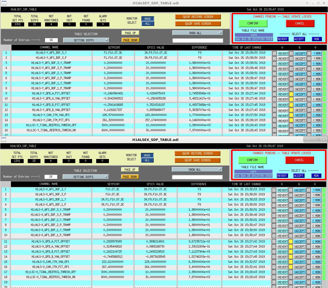
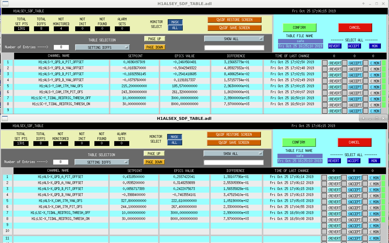
The appropriate SDF diffs were accepted and this change was implemented around 20:40 UTC today.
We are undoing this change for now so that we have the option of closing the beam diverter.