TITLE: 10/25 Day Shift: 15:00-23:00 UTC (08:00-16:00 PST), all times posted in UTC STATE of H1: Planned Engineering LOG: 14:32 UTC Vanessa to LVEA 14:49 UTC Ken to end X, looking for jacket 15:05 UTC Ken back from end X 15:29 UTC Hugh to optics lab, using fume hood 15:31 UTC Vanessa to end X 15:45 UTC Ken driving genie lift to squeezer bay to put brackets up for magnetic coils 16:02 UTC Ken back 16:05 UTC Ken back to LVEA 16:11 UTC Corey, Robert, Phillipe to cleaning area to put up magnetic coils. Opening rollup door to move coils from receiving area 16:14 UTC Karen to end Y, not VEA 16:24 UTC Karen done at end Y 17:15 UTC Richard to LVEA 17:55 UTC Kyle and Gerardo to LVEA to continue assembling turbo pumps 18:01 UTC Travis to mid X to look for cable tray parts 18:23 UTC Corey, Robert, Phillipe done 18:33 UTC Travis back from mid X 18:40 UTC Phillipe to LVEA to move equipment 18:57 UTC Gerardo out for lunch 19:00 UTC Ken done 19:18 UTC Kyle out for lunch 19:32 UTC Phillipe done in LVEA 19:48 UTC Ken back to LVEA 20:19 UTC Travis and Kyle to LVEA 20:24 UTC Travis to mid X 20:41 UTC Travis back 21:04 UTC Kyle done for day 21:10 UTC Robert and team installing coils for magnetic injections in squeezer bay 21:25 UTC Daniel to squeezer bay 22:08 UTC Phillipe out of LVEA 22:10 UTC Dan to ISCT1
I started a, basically, blank node for Jim, Jenne, and Chiara to start writing their SEI differential node. See alog52662 for more info on what they've been up to.
We will wait for the DAQ restart until Tuesday to get the new channels trendable. The node was added the Guardian overviews and I ran a check to make sure we have all of the nodes on there.
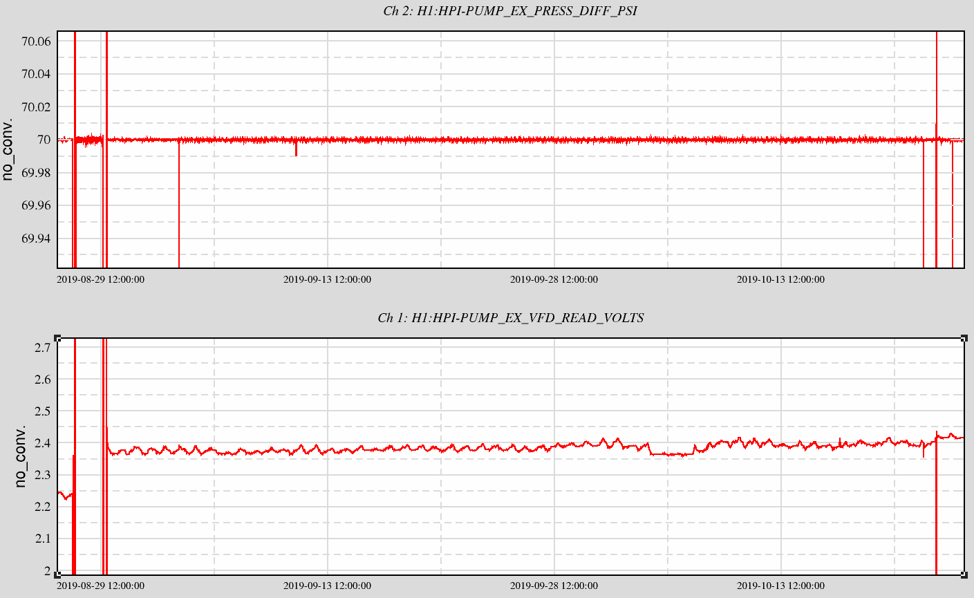
Now running for almost two months, thought it was a good thing to check on the pump at EndX, it was last checked Sept 3. The attached trends show means over the last 60 days. At the beginning is the period with the pump drive (motor speed, bottom plot) off the zoomed in scale as the sick pump maintains the PID setpoint differential pressure (top plot) for a couple days while we decide to change the pump. While the replacement pump does spin a little faster than the first one, it is a different unit after all, it isn't crazy different. And while the motor speed has increased somewhat steadily, I see a pretty clear correlation with the outside temperature and attribute the increase to the cooling mechanical room.
Bottom line--the replacement pump is performing adequately.
Dan, Cao, Craig We came back from dinner and found DRMI locked. Stepped DHARD to zero it's error signal using Hang'smove_ARM_dev.pyscript in/opt/rtcds/userapps/release/asc/h1/scripts. Got through DHARD_WFS. Spent a long time in CARM_OFFSET_REDUCTION trying obvious realignment (arm DOFs) and non-obvious realignment (IM2,3 IFI clipping) to maximize light on REFL. Failed to get more light on the diode. Pressed forward anyway, and as predicted CARM_TO_REFL killed the lock. Lost lock once going through CARM_5_PICOMETERS by hand. No discernible reason for this one, other than miserable alignment. Lost lock again in CARM_150_PICOMETERS. MICH ASC looked suspicious during this one. Big mystery from tonight is REFL light levels. They are half of what they ought to be according to the guardian. (guardian wants more than 6.5 cts on LSC-REFL_A_LF_NORM_MON, we only get 3.5)
Jenne, Jim, Chiara
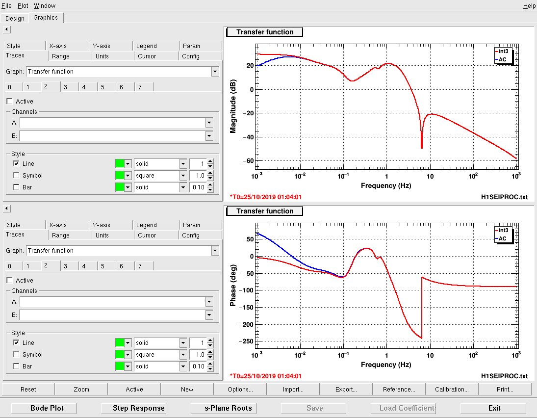
Today we tested the filters for MCL signal from the LSC filter matrix: there is an AC coupling and the int3 filter, both shown in first attachment. The int3 filter is the same controller filter that LLO is using. We didn't have time to measure ISI->MC2 for ourselves (because locking is going on), but we figured that it should be pretty similar between the sites. Perhaps we can improve further when we have a chance to measure our own plant. Jenne isn't sure why LLO is okay without AC coupling - here at LHO the DC drive to MC2 can be quite high, and we don't want to integrate that up and saturate the HAM3 ISI actuators.
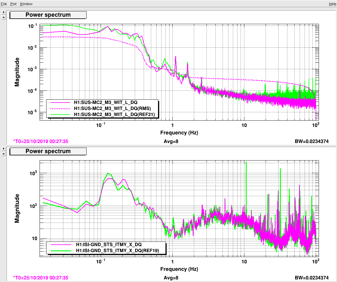
In second attachment there are plots of the result: the green line is a measurement taken while the new portion of the system was offline, while the pink trace is online. In both cases, the CPS-only offloading of differential HAM2-HAM3 motion was on. Also, today we've had sensor correction on (recall that in past alogs we've done the tests with sensor correction off since people were working in the LVEA). The two plots show the MC2 WIT and the ground motion behaviour. The online test on MC2 shows an improvement over the offline conditions below 100mHz while the ground motion does not show any variation. It is reasonable then to think that the good effect on MC2 is entirely due to the filters.
Next step will be to test PRCL offloading on HAM2 and HAM3.
Varun, Sheila, Jenne, Dan B, Georgia
Arm Alignment:
Thinking about the observations from last night alignment work, it sounds as though the X arm camera is not a good reference for our alignment from before the vent. To summarize observations after the alignment of the X arm to the camera reference yesterday:
This morning Varun and I moved ITMX back towards its alignment at the end of O3a, according to the sliders and oplev, and let the green WFS run to ETMX and TMSX, which ended up in more similar alignment to where they were in O3a, we moved PR3 back to where it was in O3a and this recovered the X transmission diode and the COMM beatnote. Then we realigned the beamsplitter to get the DIFF beatnote and MICH fringes to look OK, we have COMM at -2dBm and Diff at -13dBm.
Vertex alignment (AS_C centering):
Seismic things:
Carm offset reduction:
We had no issues with the TR_CARM or RF DARM handoffs, but lost lock a in the later CARM offset reduction stages.
Removed turbo control cable and foreline, minimized purge air flow out of pressure relief and turned off two clean rooms (North side of HAM5/HAM6. I also took an scan of the RGA while being pumped by its local 10 L/s ion pump for background subtraction purposes (2 x 10⁻⁹ Torr) but declined to expose the RGA to the relatively wet HAM6 volume. HAM6 is still in the 10-6 Torr range.
Attached is an RGA scan graphic of the site as seen by the Vertex RGA (1 sec dwell, 1300V) 1 day after we opened GV5 and GV7. PT120 indicates a total pressure of 1 x 10⁻⁸ torr. The RGA filament has been energized longer than required for the RGA to be in thermal equilibrium.
TITLE: 10/24 Day Shift: 15:00-23:00 UTC (08:00-16:00 PST), all times posted in UTC STATE of H1: Planned Engineering LOG: Gate valves are open. Commissioners are working on re-locking. 15:09 UTC Ken to end X electronics bay working on wall brackets 15:31 UTC Sheriff through gate 16:13 UTC Caltech security through gate 16:16 UTC Jim cleared test point on h1isietmx 16:25 UTC Vlad and Niko to optics lab 16:43 UTC Karen to mid Y 16:47 UTC Robert to end X 16:49 UTC Ethan and Niko to end Y to check PCAL alignment 16:59 UTC Niko transitioning end Y to laser hazard 17:10 UTC Niko and Ethan done at end Y, VEA back to laser safe 17:25 UTC Karen done at mid Y, going to end Y 17:49 UTC Karen done at end Y 18:23 UTC Stone Soup through gate 18:43 UTC Marc taking students on tour of LVEA 19:02 UTC Ken done at end X 19:06 UTC Marc and students out of LVEA 19:47 UTC h1seiproc model restart 19:59 UTC Ken to end Y 20:21 UTC Kyle climbing on HAM6 20:23 UTC DAQ restart 20:49 UTC Phillipe and Ian to end Y to set up magnetometer measurements 21:03 UTC Filiberto disconnected Beckhoff outputs for illuminator and table lights at end Y 21:09 UTC Meeting with Benton County sheriff is done 21:12 UTC Jason, Ethan, Timesh to end X, NCAL surveying 21:22 UTC Gerardo to HAM5 to tap on ion pump 21:24 UTC Travis to LVEA to look for charger 21:30 UTC Travis done 21:30 UTC Kyle done 21:31 UTC Filiberto done 21:37 UTC Ian and Phillipe back 21:53 UTC Jason back 22:00 UTC Timesh back 22:05 UTC Travis to mid X 22:15 UTC Filiberto back to end Y to reconnect Beckhoff outputs 22:22 UTC Ken done at end Y 23:10 UTC Gerardo back
The commissioning crew were having difficulties with the motion at the end stations, so it seems the TEST_SWARM state that we have been running for the last few days wasn't sufficiently quiet. Because BRSX is out of range (there seems to be some issue with the BRS epics code that I can't decipher, the ccd spots seems okay), I've made a temporary state for SEI_CONF that doesn't use BRSX, and puts ETMX in 90mhz blends called UGLY, and mostly just captures all the stuff I tried until Sheila said things looked better. Attached below is the class definition from the SEI_CONF configuration file. I think the only real difference is keeping the corner station swarm sensor correction going, turning off the BRSX sensor correction and pushing the ETMX St1 blends down to 90mhz.
class UGLY(GuardState):
"""Swarm test config for Oct 2019
"""
index = 66
goto = False
request = True
def main(self):
# HAMs SC ON
for ham_node in ham_sc_nodes:
nodes[ham_node] = 'CONFIG_SWARM'
for hpi_node in hpi_sc_nodes:
nodes[hpi_node] = 'CONFIG_SC_ON'
# Blends
nodes['ISI_BS_ST1_BLND'] = 'BLEND_QUITE250'
nodes['ISI_ITMX_ST1_BLND'] = 'BLEND_QUITE250'
nodes['ISI_ITMY_ST1_BLND'] = 'BLEND_QUITE250'
nodes['ISI_ETMX_ST1_BLND'] = 'BLEND_QUITE90'
nodes['ISI_ETMY_ST1_BLND'] = 'BLEND_QUITE250'
nodes['ISI_ETMY_ST2_BLND'] = 'BLEND_250MHZ'
nodes['ISI_ETMX_ST2_BLND'] = 'BLEND_250MHZ'
nodes['ISI_ITMY_ST2_BLND'] = 'BLEND_250MHZ'
nodes['ISI_ITMX_ST2_BLND'] = 'BLEND_250MHZ'
nodes['ISI_BS_ST2_BLND'] = 'BLEND_250MHZ'
# SC
nodes['ISI_BS_ST1_SC'] = 'CONFIG_SWARM'
nodes['ISI_ITMX_ST1_SC'] = 'CONFIG_SWARM'
nodes['ISI_ITMY_ST1_SC'] = 'CONFIG_SWARM'
nodes['ISI_ETMX_ST1_SC'] = 'CONFIG_SC_OFF'
nodes['ISI_ETMY_ST1_SC'] = 'CONFIG_WINDY'
nodes['ISI_ETMY_ST2_SC'] = 'CONFIG_FIR'
nodes['ISI_ETMX_ST2_SC'] = 'CONFIG_FIR'
nodes['ISI_ITMY_ST2_SC'] = 'CONFIG_FIR'
nodes['ISI_ITMX_ST2_SC'] = 'CONFIG_FIR'
nodes['ISI_BS_ST2_SC'] = 'SC_OFF'
@nodes.checker()
@unstall_nodes(nodes)
@check_match_gains_engaged
def run(self):
if not nodes.arrived:
notify('Not all nodes arrived')
else:
return True
Kyle, Dave:
PT343 (X1@MX) alarm restored to 5.0e-09Torr from temporary 5.0e-08Torr
PT144 (X1@LX) ditto
PT124 (Y1@LY) alarm slightly increased from 5.0e-09Torr to 7.0e-09Torr while this pressure slowly pumps down
WP8436 h1tw1 upgrade to new hardware and OS
Jonathan, Dave:
Summary: the original h1tw1 (V1 CPU, external SSD-RAID, Gentoo2.6.35) was replaced with the new style CPU+RAID unit running Debian8.
Details:
The replacement machine has been running as h1tw3 since February 2019. Today we renamed the new machine h1tw1 and turned off the old h1tw1 box. We reconfigured h1nds1 to get current raw minute data from the new unit.
Starting on Monday this week, the following was done:
Thursday work:
Tested that minute trend data is available from h1nds1 for past hour, 2 hours, day, month, 3 months (spanning all current and recent archive epochs), all looks good.
Dan B, Cao
Following from Dan's alog52621, I've been looking into a Finesse model to describe the higher order mode content in the 9 and 45 MHz sideband as we introduce differential thermal lensing with the CO2 lasers during DRMI configuration. A -5 to 5 uD lens is added to ITMX and ITMY respectively in the model. The first plot attached below shows the ratio between the higher order modes and the fundamental mode (up to the 4th order) as functions of the differential lens, obtained from Finesse amplitude detectors. The amplitude of each modes and their rate of change with respect to the change in the differential lensing can be be computed. The rate of change of ithe HG02 and HG20 amplitudes relative the HG00 are shown in the second plot for the 9 and 45 MHz sidebands. As seen here, these rates of change are not constant and dependent on the amount of differential thermal lensing. Since the CO2 lasers have been previously optimised for DRMI locking, we assume that we are are operating around the well-matched" point, around which the rates of change in HG02/HG20 amplitude are minimum at approximately 0.02-0.05%/ microDiopter change in differential lensing.
During our CO2 laser test ( alog5280), the CO2y laser power was first turned off and then doubled. to approx 2.2 W before returning to a nomnal value of approximately 0.9 W. The same procedure is repeated for CO2Y (see the first panel below). I estimated the amount of differential lensing given the change in spherical power using the zpk model of CO2 lensing in TCS simulation page. Using this estimated of differential lensing, approximate changes in the power in HG02 and HG20 can be computed using the rates of change in spherical power from the Finesse model. The last figure shows the CO2x, CO2y powers, estimated change in spherical power of by CO2 zpk model and measured ratio between the powers in HG2 and HG0 from the phase camera compared to the simulation. The shaded regions give the simulation upper and lower limit of change in HOMs powers and are determined by the maximum and minimum rate of change in a region of ± 2.5 mD of differential lensing.
In summary, the model agrees well with the measurements by the phase cameras, especially for differential lensing due to CO2y, showing 0.5%-1% change in HG20/HG02 powers during our test. There seems to be some misalignment of CO2x, as mentioned in alog52621, causing deviation from the model, which only assumes perfect differential lensing. We must have been having the ITMX and ITMY relatively well matched at current nominal powers of CO2x and CO2y, given the rate of change used in the models. There are still some uncertainty regarding the zpk models and which point of operation that we are on. We plan to perform Bayesian inference to get a better estimation of this operating point and its corresponding rate of change in HG2 powers.
[Jenne, DanB, Cao, Craig, Georgia, Stefan, Sheila]
Some notes on our first initial alignment after the vent. Despite our meeting this afternoon encouraging use of the automation system, I did much of it by hand since things were so far off.
Locking notes:
Initial alignment round 2:
Locking:
Alignment, round 3:
Plan going forward:
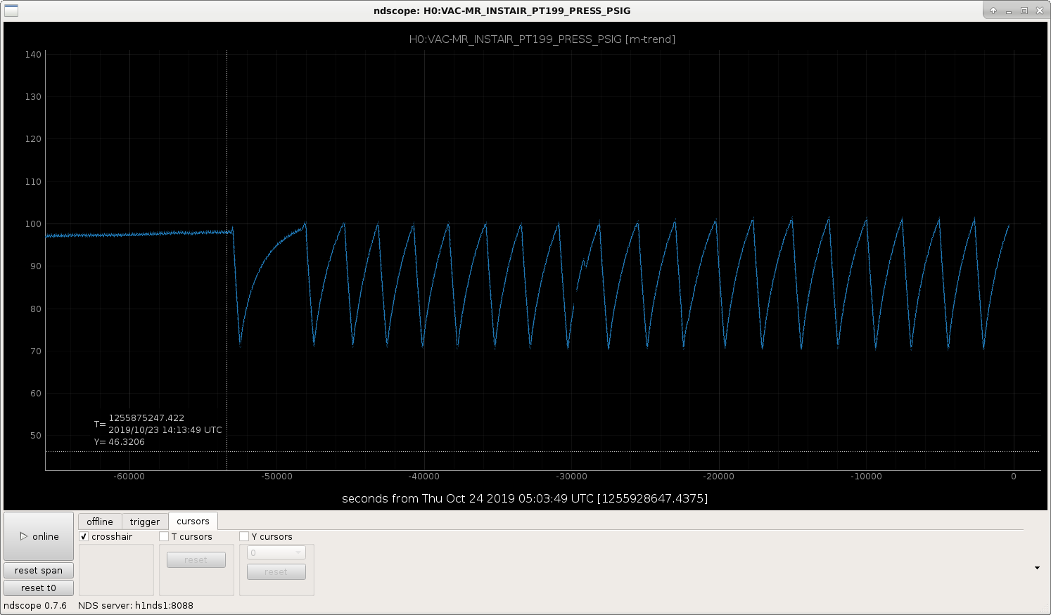
The Instrument air MR_PT199 has been going up and down, and the alarm at the operator station is going off. In the attached screenshot, it looks like it's been doing this for several hours. I've got a text out to Kyle a ~minute ago, but I'm not sure if I should do anything else for now. Advice welcome!
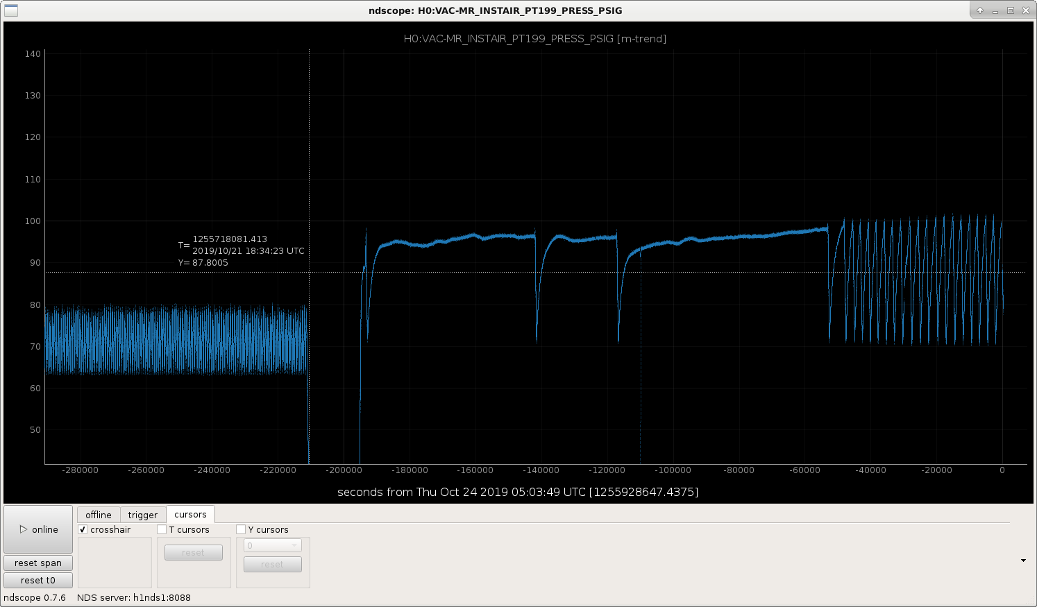
Updated with a longer trend also.
Kyle says that anything below 105 psi is okay until further notice; this is part of the system that was modified yesterday.
Sheila, Nutsinee
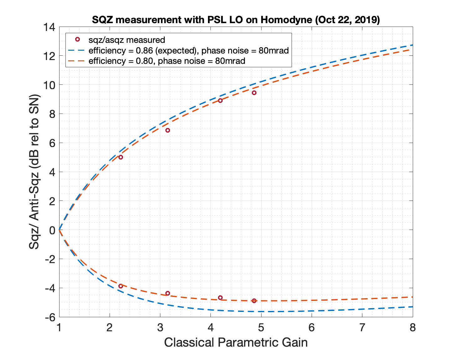
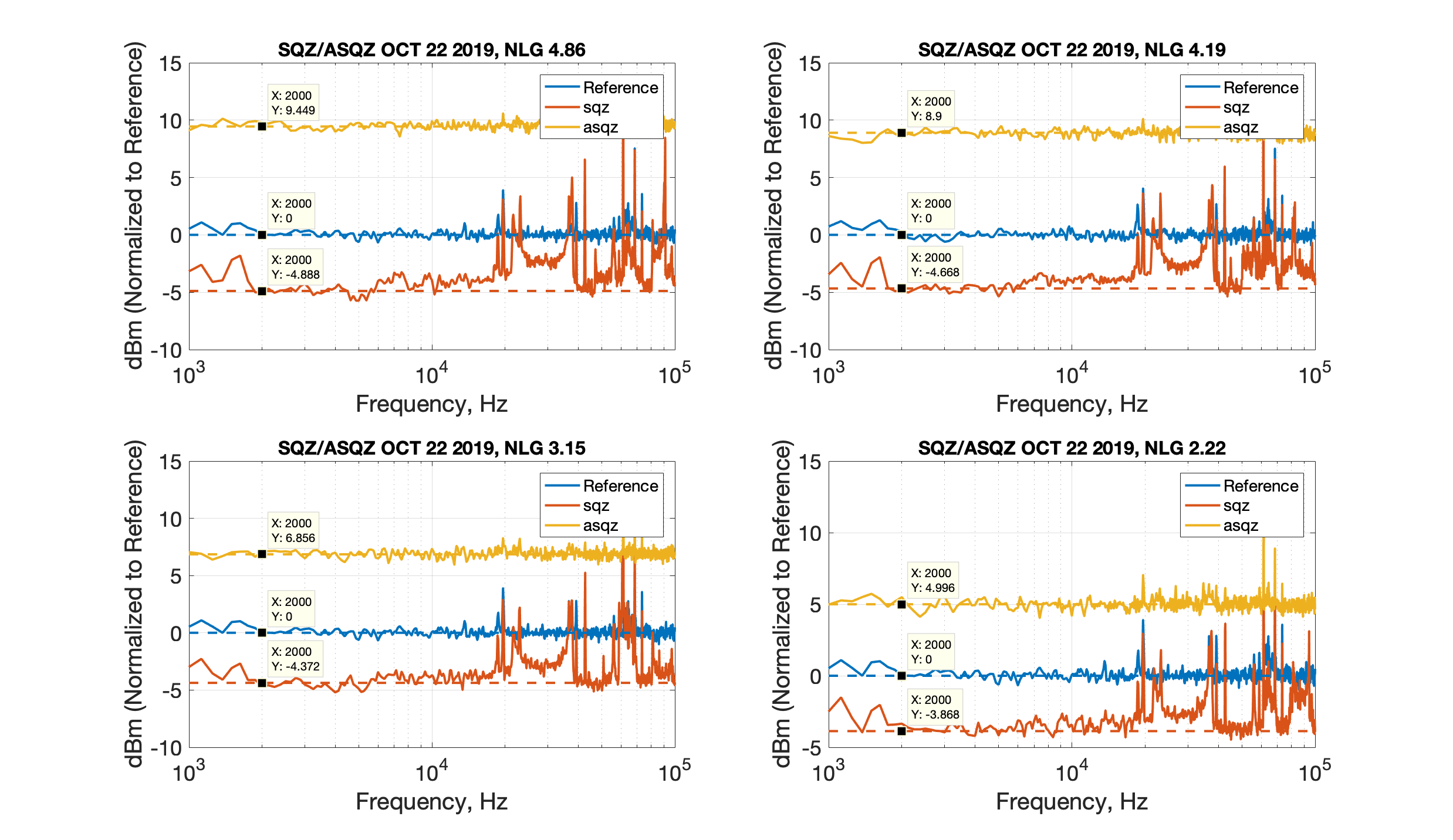
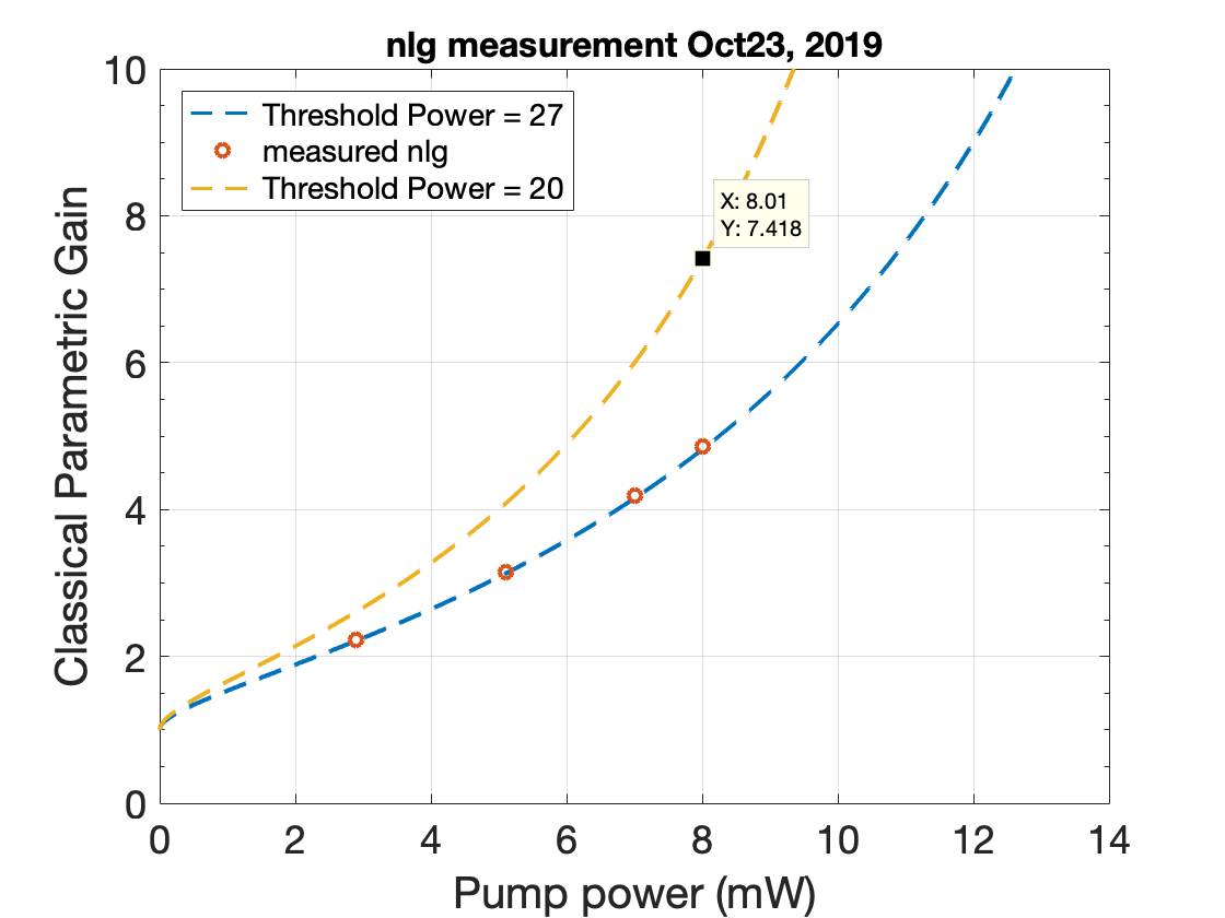
We went back and took some data today while the roughing pump was still running just to see if we could see the sqz turn around that would be an indication of phase nosie. We didn't look at any of the loop spectra and assumed that most of the phase noise came from the running pump. With the current non linear gain we have we barely reach the bottom of 80 mrad phase noise sqz curve. Assuming that the actual squeezing with the IFO has much lower phase noise than this we are going to need more non linear gain. I think the way to achieve that is to move the crystal to a new co-resonance position and hopefully we would gain some of the nlg back (given we can get the threshold power back to where it used to be, which is ~20mW). Even with 20mW threshold power we would only have the max non linear gain of 7-9 given we can only put in 20 mW into the fiber coupler. This is still not enough to see the turn around if the phase noise during the operation is really low (our rough noise budget predicted phase noise to be no more than 20 mrad).
It is also unclear at the moment that 80mrad came from the roughing pump alone. LO lock was iffy during all the measurement.
The date on these plots should be Oct 23.


We have temporarily swapped the mirror which combines the HWS path and the ALS path. This is usually a polarizing beam splitter, and we have switched it with a HR 2" optic. This clobbers the HWS path (sorry!)
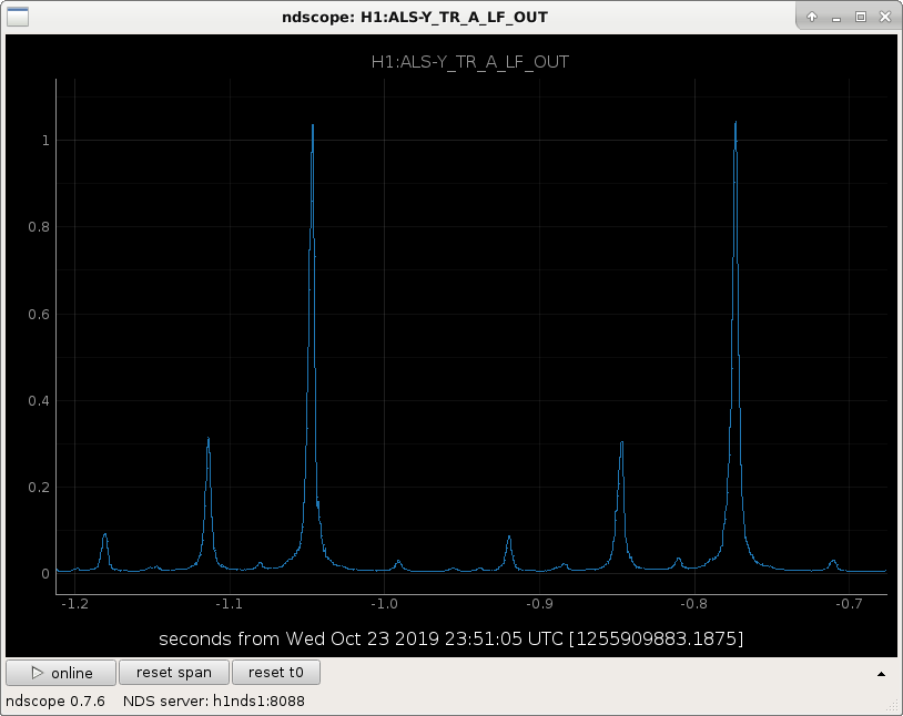
We wanted to check that some ROC on the beam combining optic is not the cause of the mode mismatch between the green beam and the Y arm. We've just opened gate valves and have the Y arm back now. A look at the Y arm while it is swinging after an initial alignment suggests this did not solve the problem (see attached screenshot). The higher order modes are still ~30% of the fundamental.
Some extra details:
I took the PBS out of the mount, and put it in the box of the new HR mirror and left it on the table. The mirror I installed is E1000652, an ATF 2" HR mirror for 532 at 45 degrees AOI. The new optic is thicker than the PBS, but the mount is such that the front face is at the same position relative to the beam, I removed an extra retaining ring from the mount to compensate for the extra thickness. I tweaked the alignment of the mirror until I saw light on the QPDs, and I checked that the PZTs were not railing.
I switched the optic back, so now everything is back to normal in the ISCTEY layout.
While I was out there I checked the Hartmann path and noted it was clipping on HWS-M5. I then stupidly tried to align the Hartmann path, tweaking HWS-S2, HWS-M5 and HWS-M6 while looking at the HWS live images (comparing to a time with the ring heater on), this is very slow to update. In the end I think I made everything worse so next week I will need TJ's help to fix it up to the beautiful alignment they had before, sorry TJ and Aidan :(
I created a guide to aligning the ETMY HWS to help recover the signal.
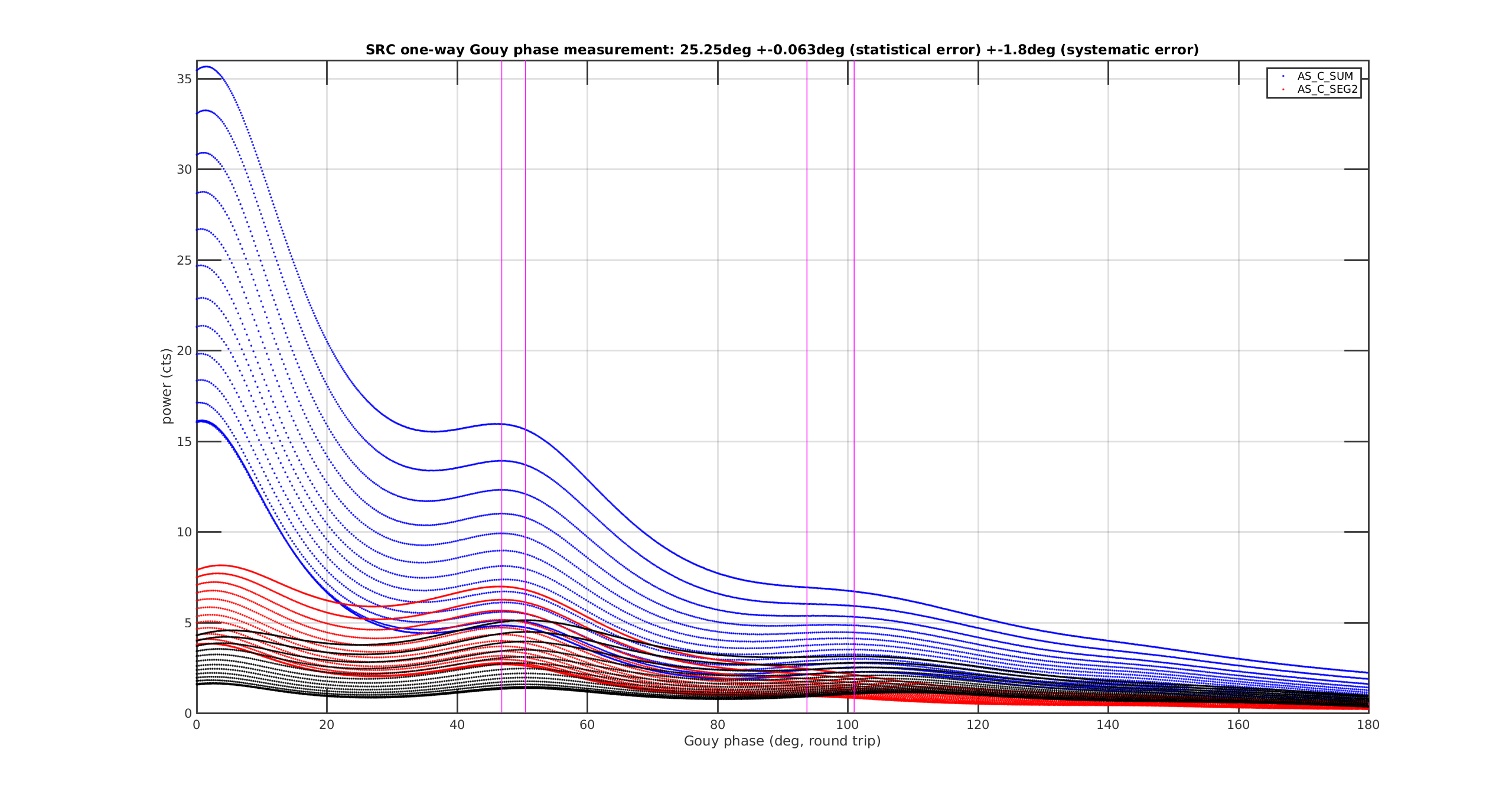
We repeated the Gouy phase measurement from yesterday (alog 52639) with the SR3 ring heater set to 0W (off).
We measured the (one-way) SRC Gouy phase to be 25.25deg +-0.06deg (statistical) +-1.8deg (systematic).
This is almost 4deg less than yesterday in alog 52639, i.e. very roughly, the ring heater adds about 1deg/W of one-way Gouy phase.
Fitting details:
- We used the s3 quadrant for finding the 00 peaks. It has the least contamination from higher order modes.
- We used 3 data sets to fit the 10 peaks: SUM (blue), SEG2 (red) and SEG1 (black).
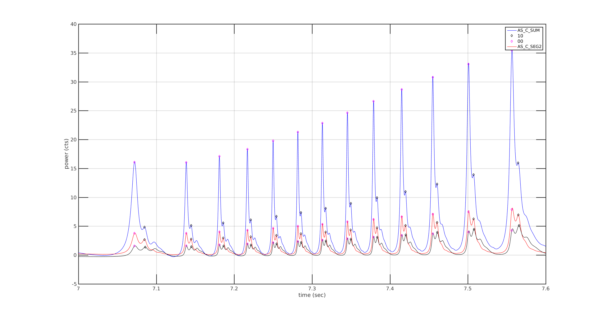
- We used all 13 fringes visible in the raw data set.
- Note that compared to yesterday's measurement we have more contamination from the 00 modes, leading to a systematic shift to lower Gouy phase if we use the SUM and SEG2 data set.
- We thus reported the result from the SEG1 data set (black) for the reported value of the Gouy phase.
- But we used the maximum difference between between the 3 data sets as reported systematic error: 1.8deg.
- The statistical error is comparatively negligible: 0.063deg.
Plots:
- Plot 1: SRC scan across 13 fringes. Blue: AS_C_SUM, Red: AS_C_SEG2, Black: AS_C_SEG1 (all derived from IOP channels).
Magenta: round trip Gouy phase fit from the blue and black results. The black result is used for the reported value.
- Plot 2: Raw data strech of the 13 fringes.
The method is described here: alogs 52639 and 52504, klogs 9241 and 9246.
The code and raw data is found in /ligo/home/controls/sballmer/20191023.
The 1deg/W value for the SR3 heater is consistent with the previous Gouy phase analysis of the SRC.
Here are some tables of the SRC gouy phase from the Finesse model. I've added in what we think is happening with thermal lensing and ITM RoCs from the TCS simulation page too. I can get up to ~25 degrees too with the SR2 shift and 4W of SR3. Script to generate these numbers is attached.
Single pass gouy [deg]
Design Finesse file
----------------------
SRX x : 19.2
SRX y : 16.9
SRY x : 19.2
SRY y : 16.9
Single pass gouy [deg]
With ITM lensing
----------------------
SRX x : 18.8
SRX y : 16.5
SRY x : 18.2
SRY y : 15.8
Single pass gouy [deg]
With ITM lensing
+ 4W SR3
----------------------
SRX x : 22.4
SRX y : 20.4
SRY x : 21.8
SRY y : 19.8
Single pass gouy [deg]
With ITM lensing
+ 4W SR3
----------------------
SRX x : 23.1
SRX y : 21.1
SRY x : 22.5
SRY y : 20.6
Single pass gouy [deg]
With ITM lensing
+ 4W SR3
+ 5mm SR2 shift
----------------------
SRX x : 26.1
SRX y : 24.4
SRY x : 25.7
SRY y : 23.9
To get up to something like 29 degrees I have to start doubling the distance SR2 is shifted or doubling the SR3 heater power
Single pass gouy [deg]
With ITM lensing
+ 4W SR3
+ 10mm SR2 shift
----------------------
SRX x : 29.0
SRX y : 27.4
SRY x : 28.5
SRY y : 26.9
Single pass gouy [deg]
With ITM lensing
+ 8W SR3
+ 5mm SR2 shift
----------------------
SRX x : 29.6
SRX y : 28.0
SRY x : 29.1
SRY y : 27.5
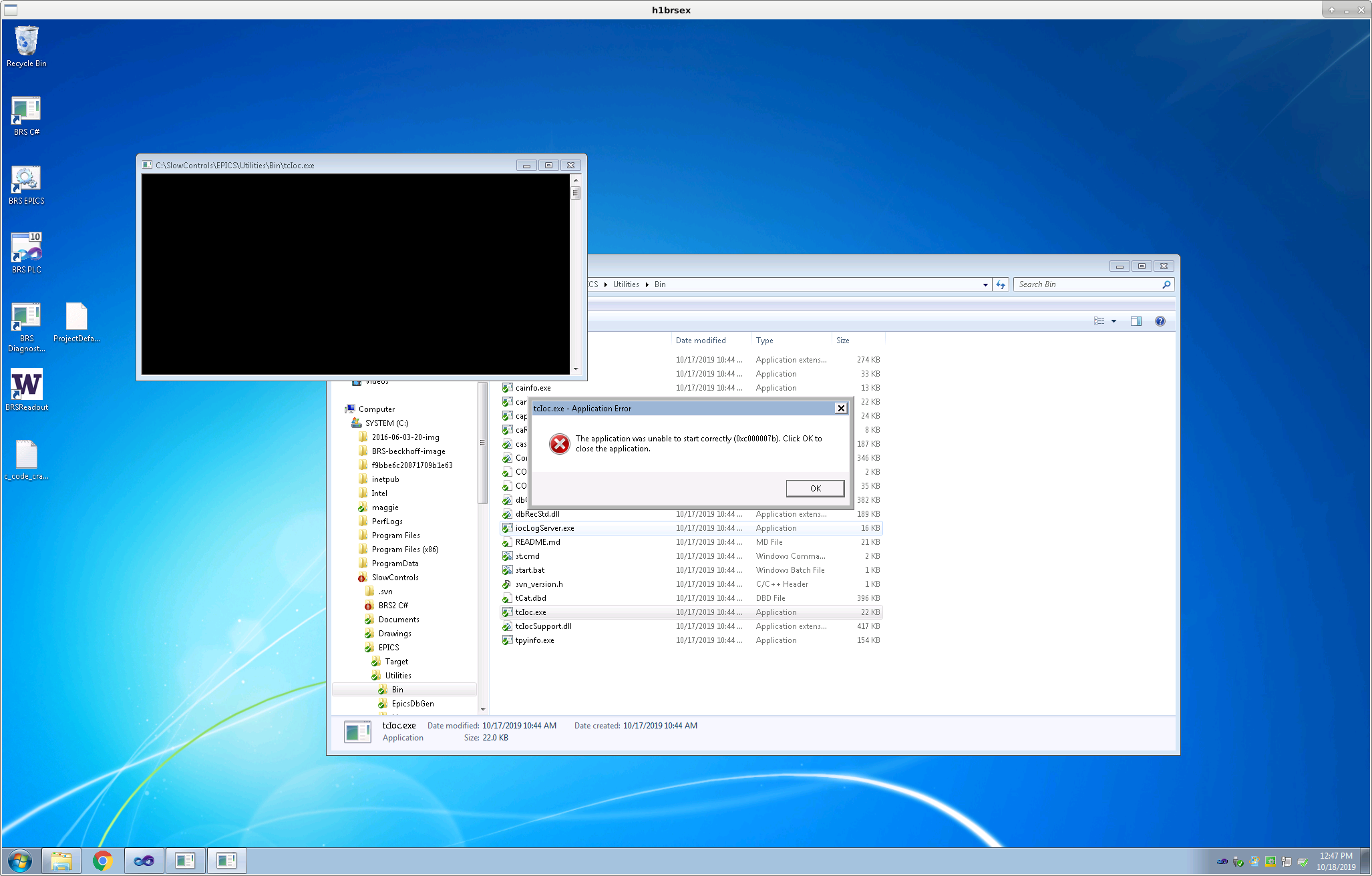
Oct. 18 - 22 2019 h1brsex: After I ran svn update on C:\SlowControls the applications in trunk/EPICS/Utilities/Bin gave the error in the attached screenshot. I have reverted the working copy of this directory to revision 4189 to get the EPICS IOC to run. I scanned for the Beckhoff terminals that Filiberto installed and added them to the IO in the solution. I added the PLC variables and code for the addition of the heater and linked the variables to the added IO terminals as instructed by Eyal. There was some confusion because the size of the HEATCTRLOUT PLC variable and the EL4134 channel it links to do not match. Only the first 16 bits of the PLC variable are linked. I removed from svn the files in trunk/TwinCAT3/BRS/H1BRSEX that are automatically generated. I fixed the paths in brsxEPICS.bat and brsxEPICS.cmd. These were pointing to an old copy of the code that is not in svn. I added lines to brsxEPICS.cmd to generate the ini and req files. I installed WinSCP and copied the generated ini and req files to /opt/rtcds/userapps/release/ecat/h1brsex. h1brsey: I ran svn update. On this computer the applications in trunk/EPICS/Utilities/Bin ran without error. The additional Beckhoff terminals have not yet been connected at this station so I only added the PLC code. I removed from svn the files in trunk/TwinCAT3/BRS/H1BRSEY that are automatically generated. I changed the names of the ini and req files in brsyEPICS.cmd to h1brsey.ini and h1brsey.req. I installed WinSCP and copied the generated ini and req files to /opt/rtcds/userapps/release/ecat/h1brsey.
Added terminals and links for h1brsey.