Displaying reports 37981-38000 of 89075.Go to page Start 1896 1897 1898 1899 1900 1901 1902 1903 1904 End
Reports until 12:33, Wednesday 23 October 2019
H1 PSL (PSL)
corey.gray@LIGO.ORG - posted 12:33, Wednesday 23 October 2019 (52648)
PSL Chiller Water Level Top-Off (FAMIS #10532)
Topped off Crystal Chiller with 80 mL.  Diode Chiller OK.  
Filters look fine (slight yellow tint of Crystal filter [known item]).
LHO VE (VE)
gerardo.moreno@LIGO.ORG - posted 10:29, Wednesday 23 October 2019 (52647)
NEG Pumps 1, 2 and 3 Valved In

After removing all connections to the NEG pumps, their gate valves were opened to the main volume, time 16:26 utc.

H1 CDS (ISC)
filiberto.clara@LIGO.ORG - posted 10:27, Wednesday 23 October 2019 (52646)
LSC AA Chassis Modified

WP 8375
E1900130
E1900105

Three of the four LSC AA chassis in the corner station have been modified per ECR1900105/E1900130. Input buffer U2 was replaced on all channels with faster slew rate opamp ADA4622.

S1102784 S1301308 S1102789

F. Clara, E. Merilh, M Pirello

H1 ISC
stefan.ballmer@LIGO.ORG - posted 09:28, Wednesday 23 October 2019 (52645)
SR3 ring heater turned off

We turned the SR3 ring heater from 4W to 0W at GPS 1255883240, Oct 23 2019 16:27:02 UTC. Once the system equilibrates, we plan to take another SRC Gouy phase measurement.

H1 CAL (CAL)
timesh.mistry@LIGO.ORG - posted 09:07, Wednesday 23 October 2019 (52501)
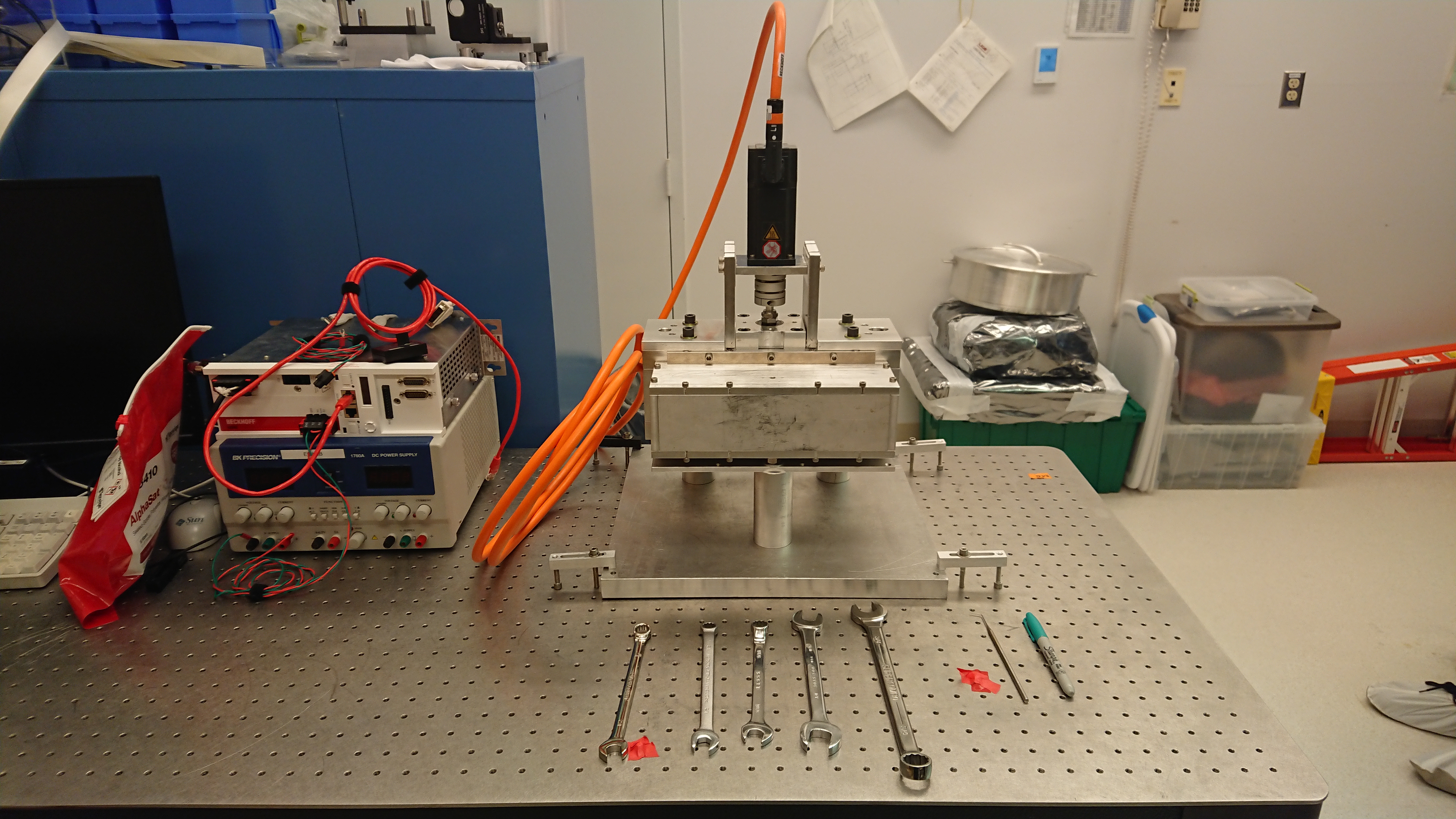
NCAL Update -- Reassembly of NCAL on 15th October 2019

[Corey Gray, Timesh Mistry]

Delayed post from 15th Ocotber 2019, we have disassebled and re-assembled the NCAL, hopefully for the final time. 

NCAL Dissassebly 
================

Using 3mm allen key, unbolt the grub screw holding the motor coupler to the NCAL shaft. Do not undo the bolt fully, only enough so that it is not clamping the coupler to the shaft.
using a 3/16 allen key, unbolted the 4 bolts that hold the motor to the "L" bracket. Do not undo the bolts fully, enough so that the motor can slide off the shaft. The metal shim are not uniform and thier placement is important.
They are marked left and right with respect to the breaing housing assembly cut out. 
Using a 5/16 allen key, remove the bolts holding the "L" brackets to the NCAL top frame.
Using a 5/16 allen keym remove the bolts bolding the NCAL plate to the NCAL lower frame.
Lift the NCAL up and off the NNCAL plate, ensuring the shaft does not impact any surfaces. Place the NCAL on its' side and using a 3/16 allen key to remove the bolts holding the side covers.
Remove the side covers and place the NCAL upright, using the sidecover to rest the NCAL upon. 
Using a 5/16 allen key, remove the 4 bolts holding the top bearing assembly. The bearing assebly will lift off.
Using a 5/16 allen key, remove the 4 bolts that hold the top frame to the side frame.
Insert a bolt between the alignment pins and, using a few drops of IPA, wind in each bolt evenly until the top frame is loose.
The rotor can lift out and using a 3/16 allen key, the collars can be removed from each side of the rotor and the collars will slide off and shaft will pull out. 
Insert a bolt between the alignment pins and, using a few drops of IPA, wind in each bolt evenly until the top frame is loose.
Use 5/32 allen key to remove (6) #10-32 bolts & remove Back Plate (bolts & collar were cleaned with alcohol wipes).
Use 3/16 allen key, to remove (2) 1/4-20 attachement bolts & (1) 1/4-28 collar bolt of Bottom collar (bolts & collar were cleaned with alcohol wipes).

NCAL Assembly
==============


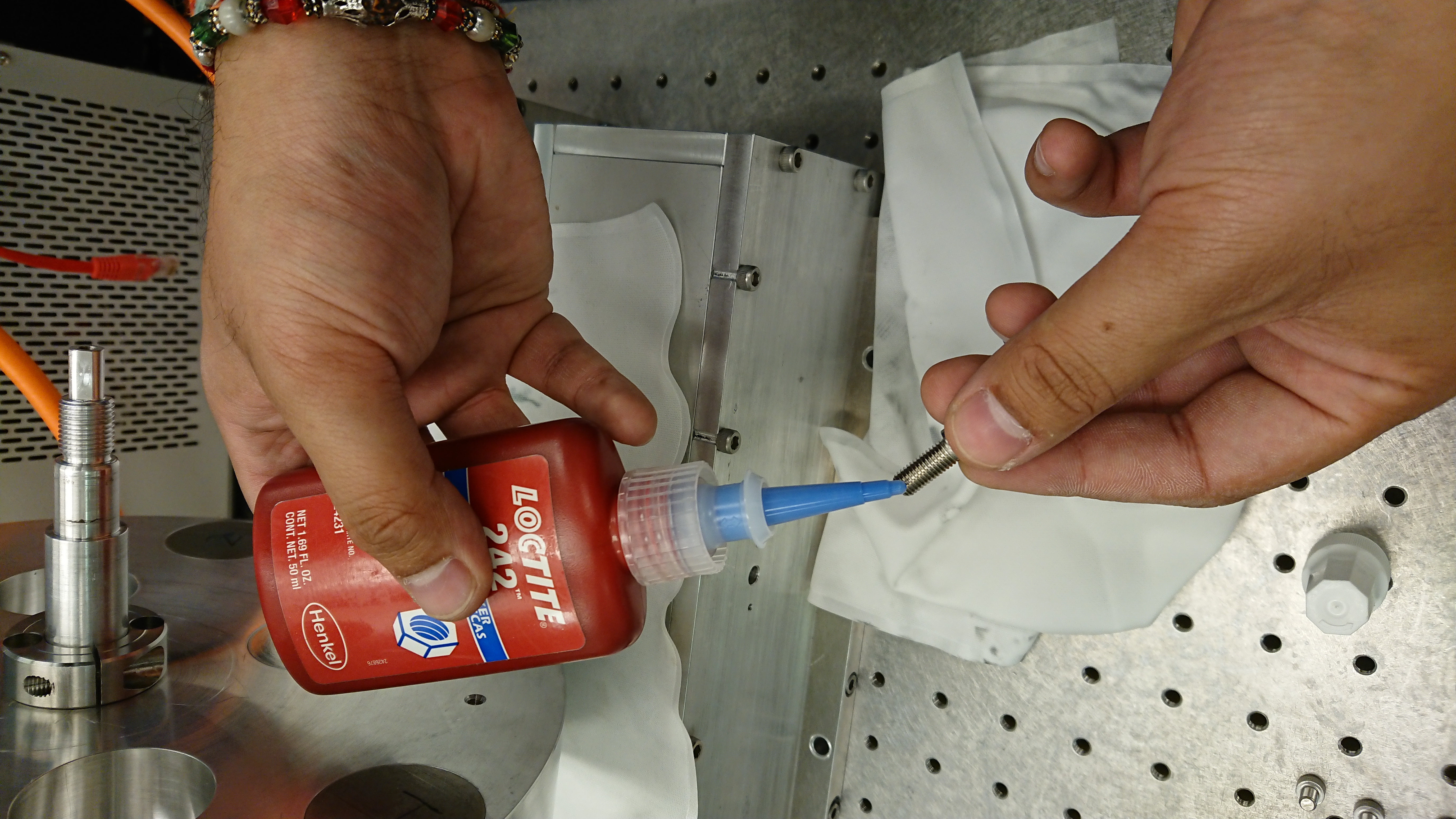
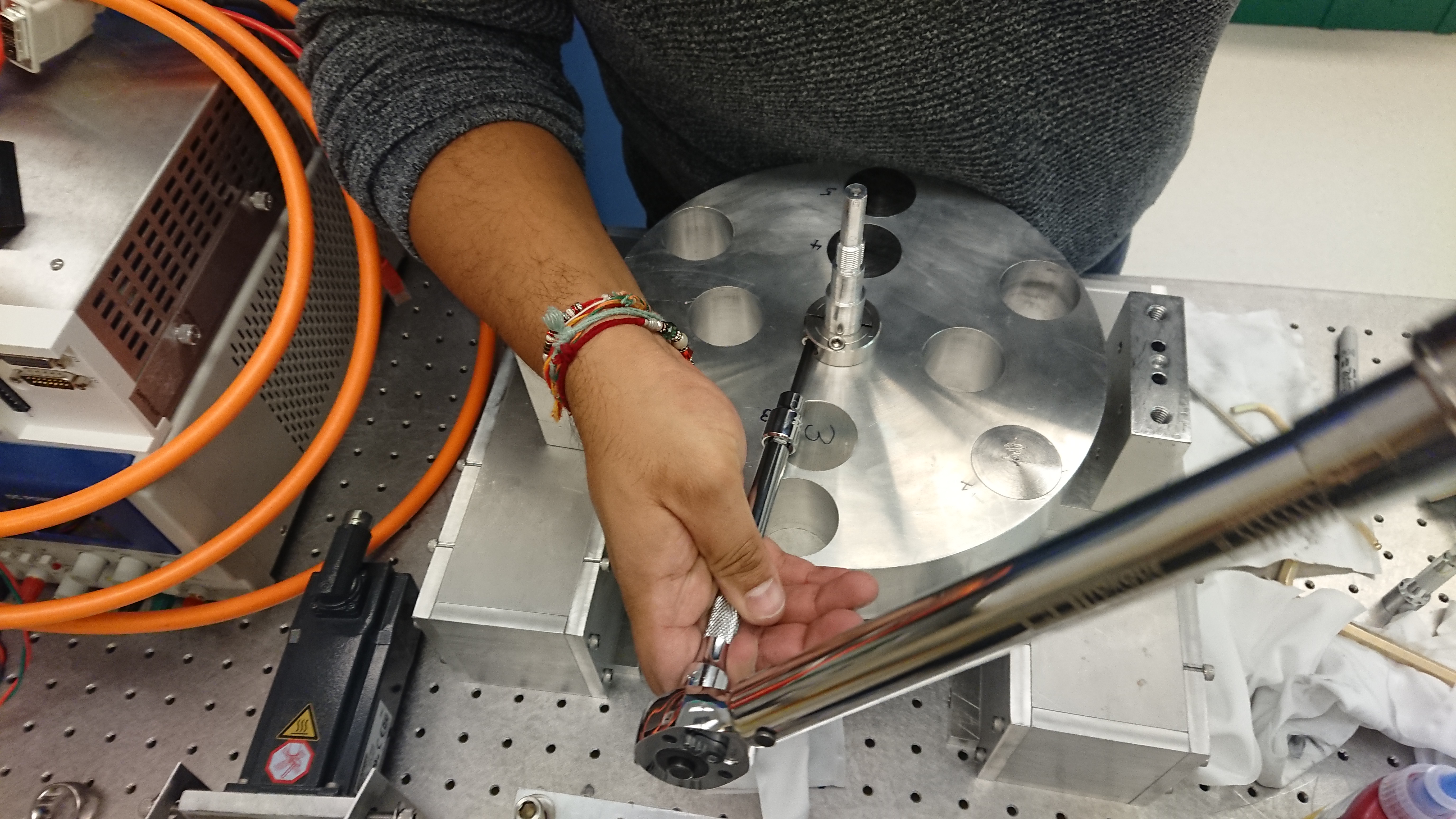
Install Bottom Collar.  Apply Loctite to (3) Bottom Collar bolts (1/4-20 & 1/4-28) & torque down all three bolts (torque value of 7 ft-lbs used).  Used an extension w/ bevel for torque wrench.
Install Back Plate.  Apply Loctite to (6) #10-32 bolts & use them to attach the Back Plate.  Turn bolts slowly by hand and check that Back Plate is installed flushly with the Main Rotor.  Torque all (6) bolts hand tight (or 2.6 ft-lbs).
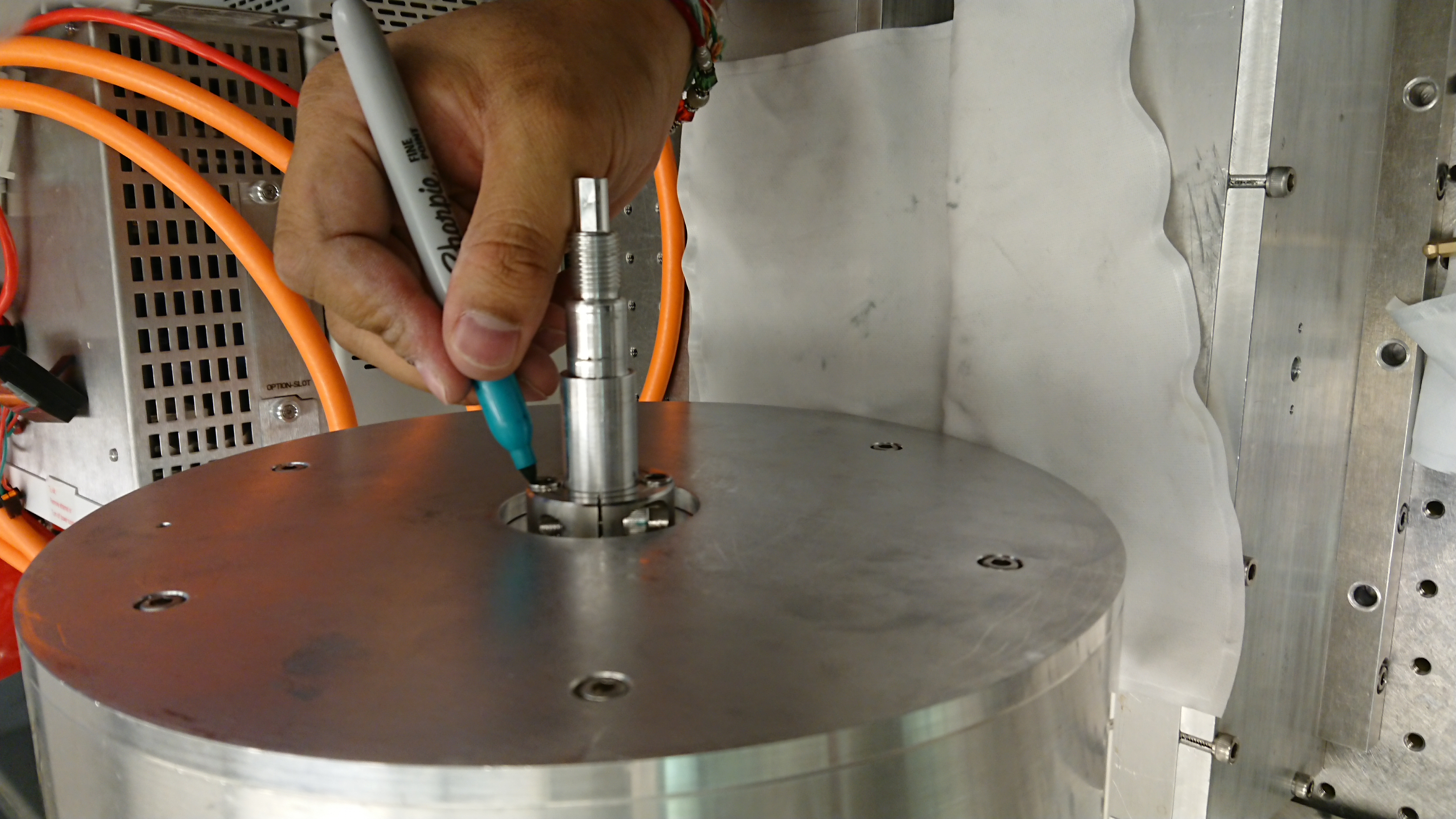
Sharpie marker used to mark bottom bolts which were torqued.
For Lower Frame assy, apply Loctite to (4) 3/8-16 bolts (confirm bolt size!), install, and torque them to 20 ft-lbs.
For Lower Frame assy, install Lower Bearing Assy loosely (for fit onto Rotor Shaft).
Install Top Collar.  Apply Loctite to (3) Top Collar bolts (1/4-20 & 1/4-28) & torque down all three bolts (torque value of 7 ft-lbs used).  Used an extension w/ bevel for torque wrench (see photos).
Lift Main Rotor Assy, place pair of shims between Main Rotor & Lower Frame Assy.
Install Upper Frame Assy.  First line up "alignment marks" of Upper  & Lower Frame Assys.  Secondly, use pins of Upper Frame to attach to Lower Frame.  Finally apply Loctite to (4) 3/8-16 bolts (confirm bolt size!), and slowly tighten
bolts together at roughly 1/4 turn at a time.  When there is contact between Upper/Lower Frames, torque to 20 ft-lbs.
Loosely install Top  Bearing Housing (for fit onto Rotor Shaft).  Make sure to line up cut out of Top Bearing Housing with cut out of Upper Frame.
Confirm play of shaft is good & there is no wobbling.  
Once shaft is acceptable, torque (4) Top Bearing Housing 3/8-16 bolts (confirm bolt size!) to 20 ft-lbs.
Install Top Shaft Nut & Lock Nut.  Install such that the distance from the top surface of Main Rotor & bottom surface of Upper Frame is about 7mm.
Lift Assy, as is, to now access Bottom Bearing Housing.
One bolt at a time, remove (4) Bottom Bearing Housing 3/8-16 bolts (confirm bolt size!), apply Loctite, reinstall, and then finally torque all (4) bolts to 20 ft-lbs.
Install Bottom Shaft Nut & Lock Nut.  Install such that the distance from the top surface of Main Rotor & bottom surface of Upper Frame is about 6-7mm.
Lock upper & lower shaft nuts by using a pair of 3/4" spanners.
Install both Side Covers.  Each one needs (6) 1/4-20 bolts and they are only torqued hand-tight.
Attach NCal Assy to Base Plate with (4) 3/8-16 bolts (confirm bolt size!) and torque them hand-tight.


NCAL General Notes
==================

Reference marks built into the NCAL as part of the design for alignment when surveying it in.
Shorter dowel pins for easier and disassembly and reassembly.
Better tolorances on bolt holes and bearing alignement.
Better consideration for users who have to assemble/disassemble unit.
Have a defined height for the NCAL motor on the L brackets.

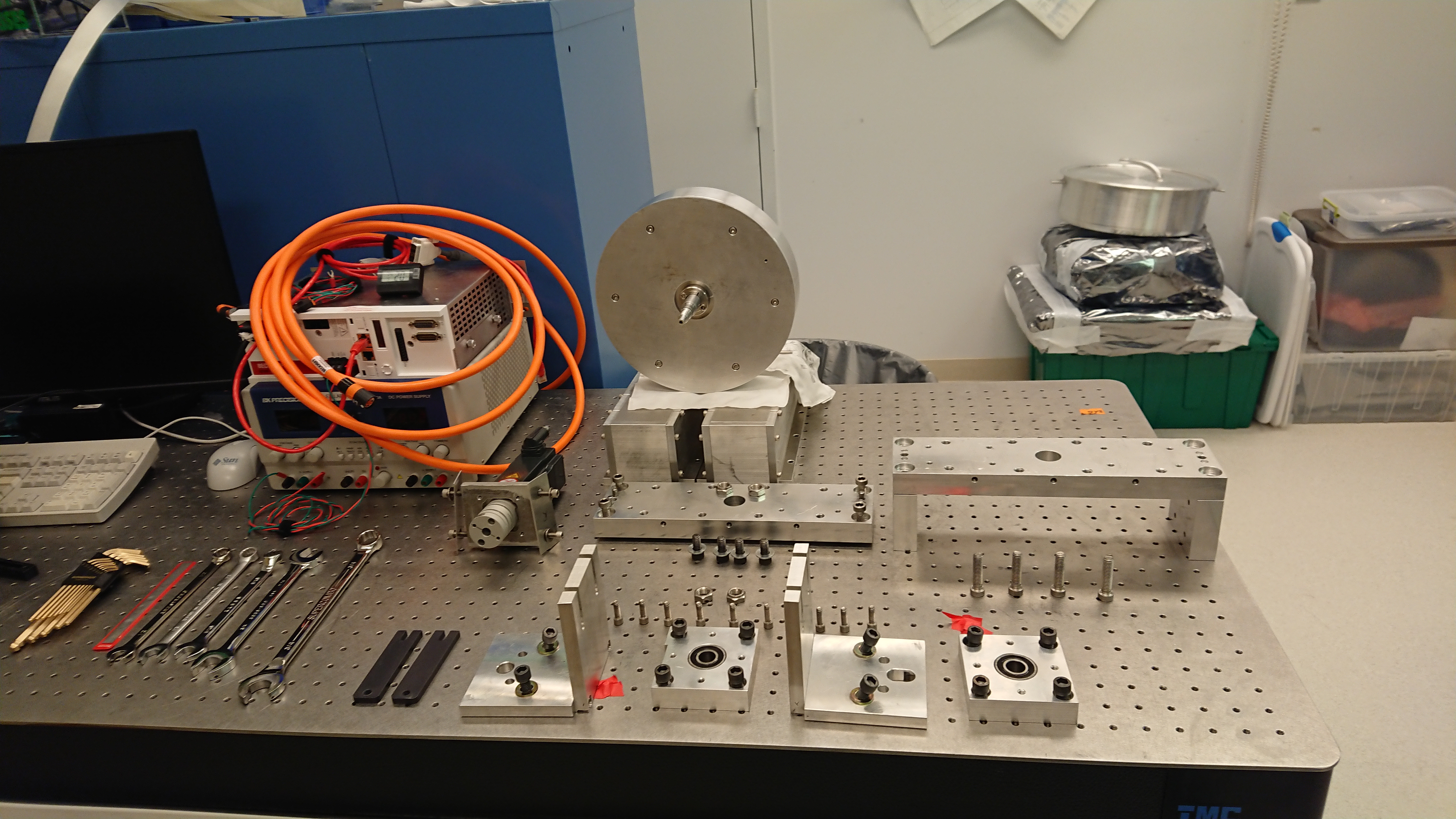
Images attached to this report
H1 General
jeffrey.bartlett@LIGO.ORG - posted 08:07, Wednesday 23 October 2019 (52643)
Ops Day Shift Transition
Ops Shift Transition: 10/23/2019, Day Shift 15:00 – 23:00 (08:00 -16:00) - UTC (PT)
State of H1: Unlocked
Intent Bit: Engineering
Weather:  Skies are mostly sunny today; cloud cover increasing in the afternoon and early evening. The winds are Calm. Temperatures are in the upper 40s and forecast into the lower 60s this afternoon.   
Primary 0.03 – 0.1Hz: 0.00xum/s
Secondary 0.1 – 0.3Hz: 0.0xum/s
Outgoing Operator: N/A
Quick Summary: Locking, upgrades, and post vent recovery work continues.   
H1 SQZ (SQZ)
nutsinee.kijbunchoo@LIGO.ORG - posted 23:02, Tuesday 22 October 2019 - last comment - 04:59, Wednesday 23 October 2019(52640)
Squeezer Homodyne Recovery

Sheila, Daniel, Nutsinee


Quick report on the homodyne recovery. 

It's squeezing!

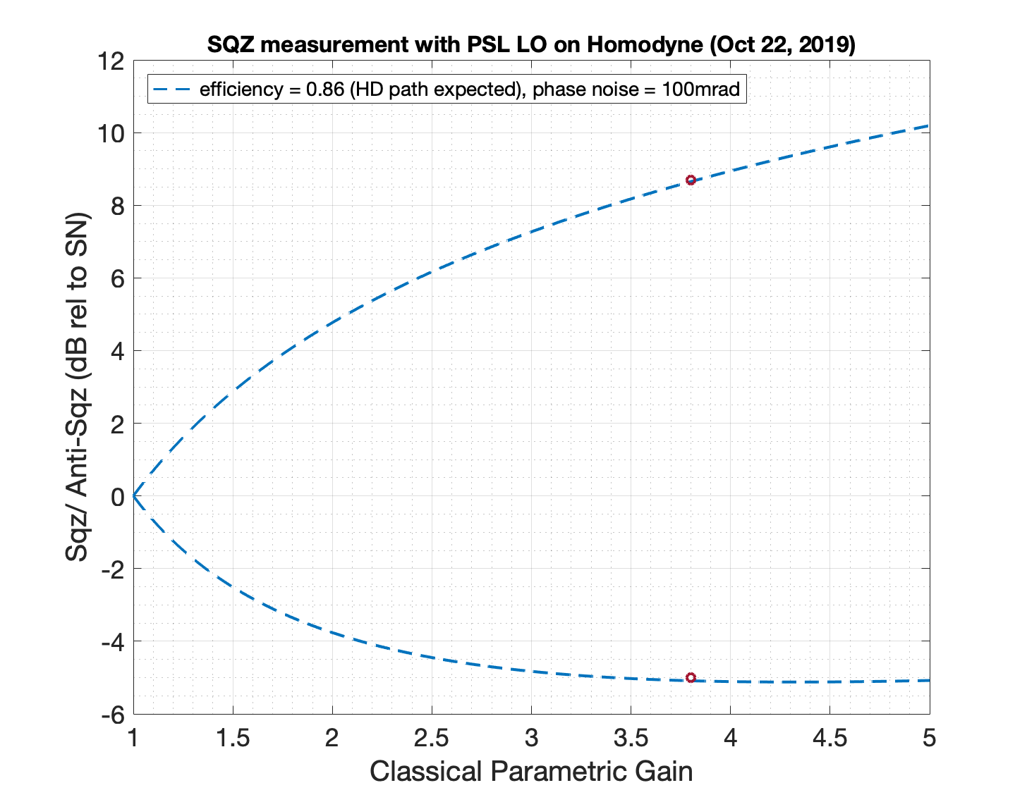
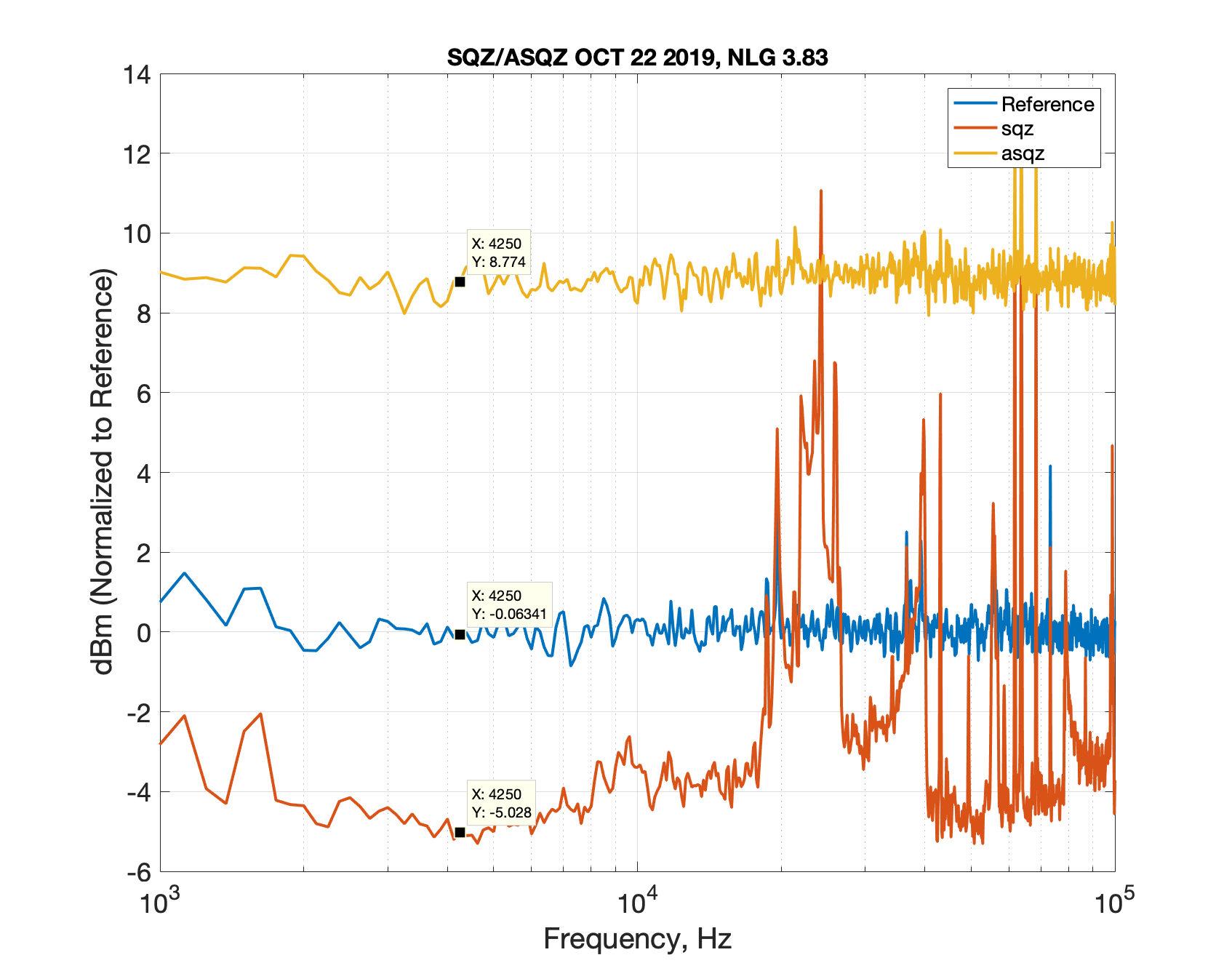
We observed ~5dB of squeezing and ~8.7dB of anti-squeezing at non linear gain of 3.8.

7mW was sent to the OPO (refl readback before OPO locked). 2.6mW transmitted (during OPO locked).

Fringe Visibility was 97.5% on PD2 and 98% on PD1. The Homodyne was balanced with 0.5mW PSL LO into each diode (1mW LO total). We had about 20dB of clearance from dark noise.

We made sure that every loop has reasonable phase margin. OPO UGF was 1.2kHz, CLF UGF was 3.6kHz, and LO UGF was 17.8kHz (homodyne locking). 

The phase noise is high likely due to the roughing pump running next to SQZT6 (if we trust the fit with single data point at all). We will take more measurements later when it's more quiet out there. 

The 80MHz VCO servo ran away causing trouble locking LO loop (probably gave me trouble with the fringe visibility earlier too as homodyne response is frequency dependent). Something to keep an eye out for next time. 

The sqz noise at f>10kHz could be due to us changing CLF phase without keeping track of how well the LO was locked. The squeezing trace was responding to the CLF phase delay changes so LO was at least locked (somewhat). This could easily be another source of phase noise. 


Images attached to this report
Comments related to this report
michael.landry@LIGO.ORG - 04:59, Wednesday 23 October 2019 (52642)

Looking good!

H1 ISC
stefan.ballmer@LIGO.ORG - posted 21:40, Tuesday 22 October 2019 - last comment - 17:13, Monday 20 April 2026(52639)
SRC Gouy Phase measurement (without even locking SRMI)

Varun, Stefan

We measured the (one-way) SRC Gouy phase to be 28.97deg +-0.11deg (statistical) +-0.43deg (systematic).
We used a method pioneered in KAGRA (klog 9241 and 9246). A similar method was used for the PRC Gouy phase measurement(alog 52504).

Plots:
 - Plot 1: SRC scan across 6 fringes. Blue: AS_C_SUM, Red: AS_C_SEG2 (both derived from IOP channels). Magenta: round trip Gouy phase fit from the two results.
 - Plot 2: Raw data strech of 6 best fringes.

Method:
- Align BS and SRM (in SRY) carefully (especially BS)
- Misalign SRM by 70 urad (we did pos pitch)
- Let SRMI freely swing (i.e. SRM and BS aligned, PRC misaligned)
- SRCL1 and MICH1 gains 0 (we don't need the control loops)
- Put an offset in SRCL2_OFFSET (we used -1e6cts)
- Turn off all whitening on ASC-AS_C
- We want the LSC trigger to fire and stay latched (and apply the offset) when ASC-AS_C reaches the darkest possible spot.
  This corresponds to the BS in the correct position, increasing the finesse of the SRC to its maximum.
- We achieved that with a negative trigger matrix element, a slightly positive enable threshold (since AS_C swing slightly negative), and a very negative disable threshold
  We used: H1:LSC-TRIG_MTRX_4_14 =-100, H1:LSC-SRCL_TRIG_THRESH_ON = 0.015, H1:LSC-SRCL_TRIG_THRESH_OFF = -100
- To read the data we need the highest possible data rate. So in addition to H1:ASC-AS_C_NSUM_OUT we recorded the IOP channels
  H1:IOP-ASC0_MADC6_TP_CH9, H1:IOP-ASC0_MADC6_TP_CH10, H1:IOP-ASC0_MADC6_TP_CH11, H1:IOP-ASC0_MADC6_TP_CH12
- Those IOP channels are before the fixed anti-whitening filter. So we did the anti-whitening filter in diaggui ('zpk([40],[0.4],1,"n")').
- The 4 quadrants of ASC-AS_C saw different combinations of the higher order modes.
- We used SEG4 (CH9) for finding the 00 modes.
- We used SEG2 (CH11) and the sum of all 4 segments for 10 modes (red and blue traces respecively).
- We chose a bank of 6 fringes with very low AS_DC values - those have the highest finesse.
- A spline fit was used to interpolate the time to degrees in-between 00 peaks.
- We calculated the mean from the red and blue traces separately. Their mean is reported as final value.
- We calculated the standard deviation of the mean from the red and blue traces separately. The maximum of the two errors is reported as statistical  error.
- The difference between the red and blue result is reported as systematic error.

The code and raw data is found in /ligo/home/controls/sballmer/20191022.
 

Images attached to this report
Non-image files attached to this report
Comments related to this report
stefan.ballmer@LIGO.ORG - 09:26, Wednesday 23 October 2019 (52641)

Should add that the SR3 ring heater, as well as the ITM TCS system,  was turned on during the measurement. Snap shots are attached.
The time of measurement was GPS 1255829128, Oct 23 2019 01:25:10 UTC.

Images attached to this comment
sheila.dwyer@LIGO.ORG - 17:13, Monday 20 April 2026 (89955)

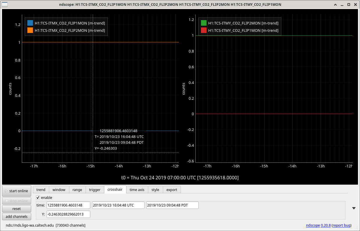
At the time of this measurement, CO2 heating was central. The CO2 FLIP1MON was 0 and FLIP2MON was 1.  Comparing this to the current values and the MEDM that says we are currently using annular heating, I believe this means that these measurements were done with central CO2. 

Images attached to this comment
H1 ISC
varun.srivastava@LIGO.ORG - posted 20:50, Tuesday 22 October 2019 (52637)
Sensor Correction Turned Back on at 20:42 PST
Stefan, Varun

The following configuration settings were restored:

SEI:ISI configuration state changed TEST_SWARM-> SC_OFF_NOBRSXY
SEI:ISI DIFF: Output limiters: HAM3: SUSINF_X gain =0 -> gain=1.


ASC: ASC_C whitening stages 1 and 2 turned on.
H1 ISC (AOS, ISC)
georgia.mansell@LIGO.ORG - posted 20:02, Tuesday 22 October 2019 - last comment - 02:53, Thursday 24 October 2019(52636)
ALSy Bad Green Mode Matching - Round 5

Keita, Georgia

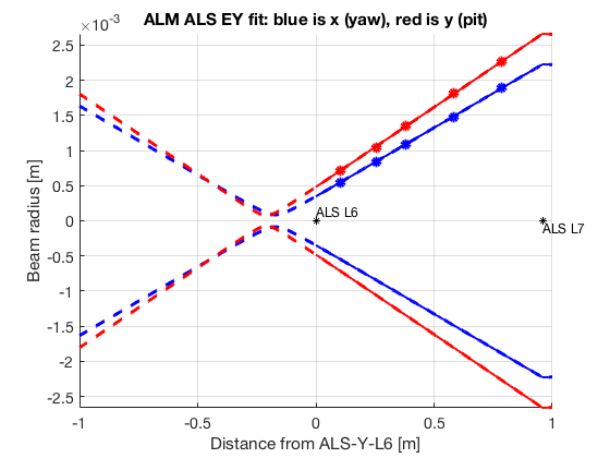
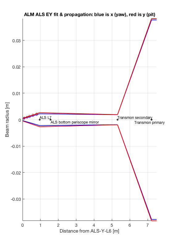
Today we took a profile of the ALS beam on ISCTEY, measuring the beam size for the input beam (going to the ETM) between the two beam expanding telescope lenses (first attachment). We took the same measurement at end X yesterday, and the beam has been measured in a couple of different positions at on ISCTEY previously (alog 52576 and links therein).

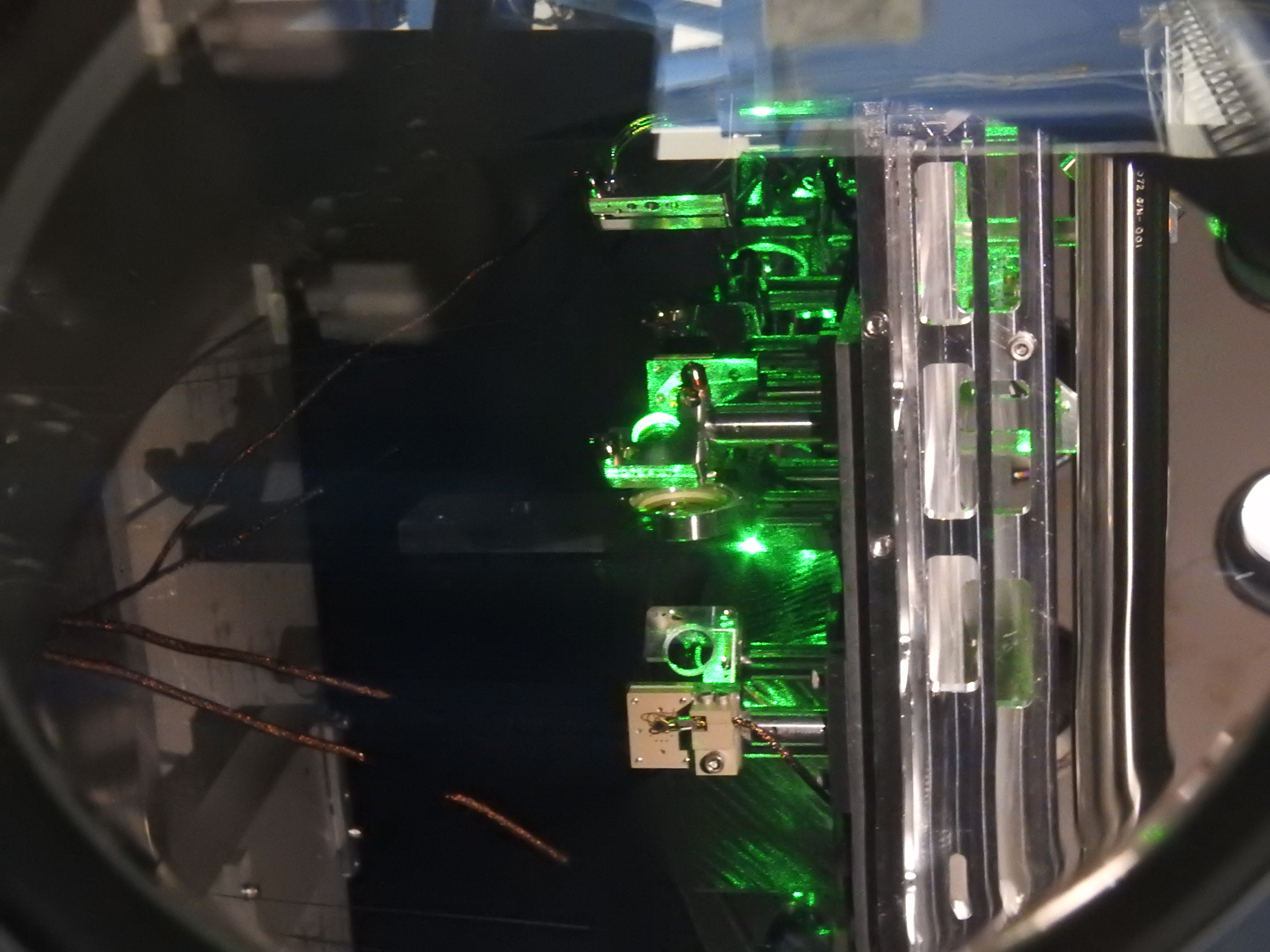
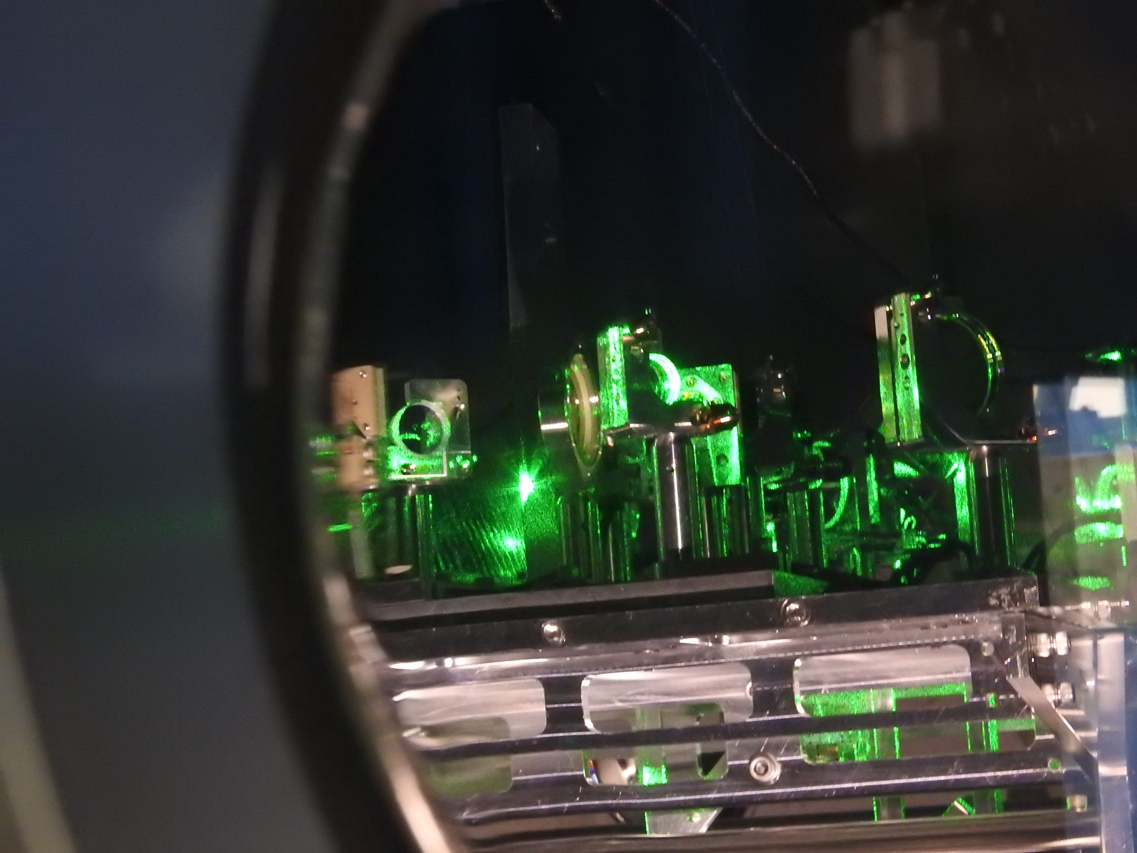
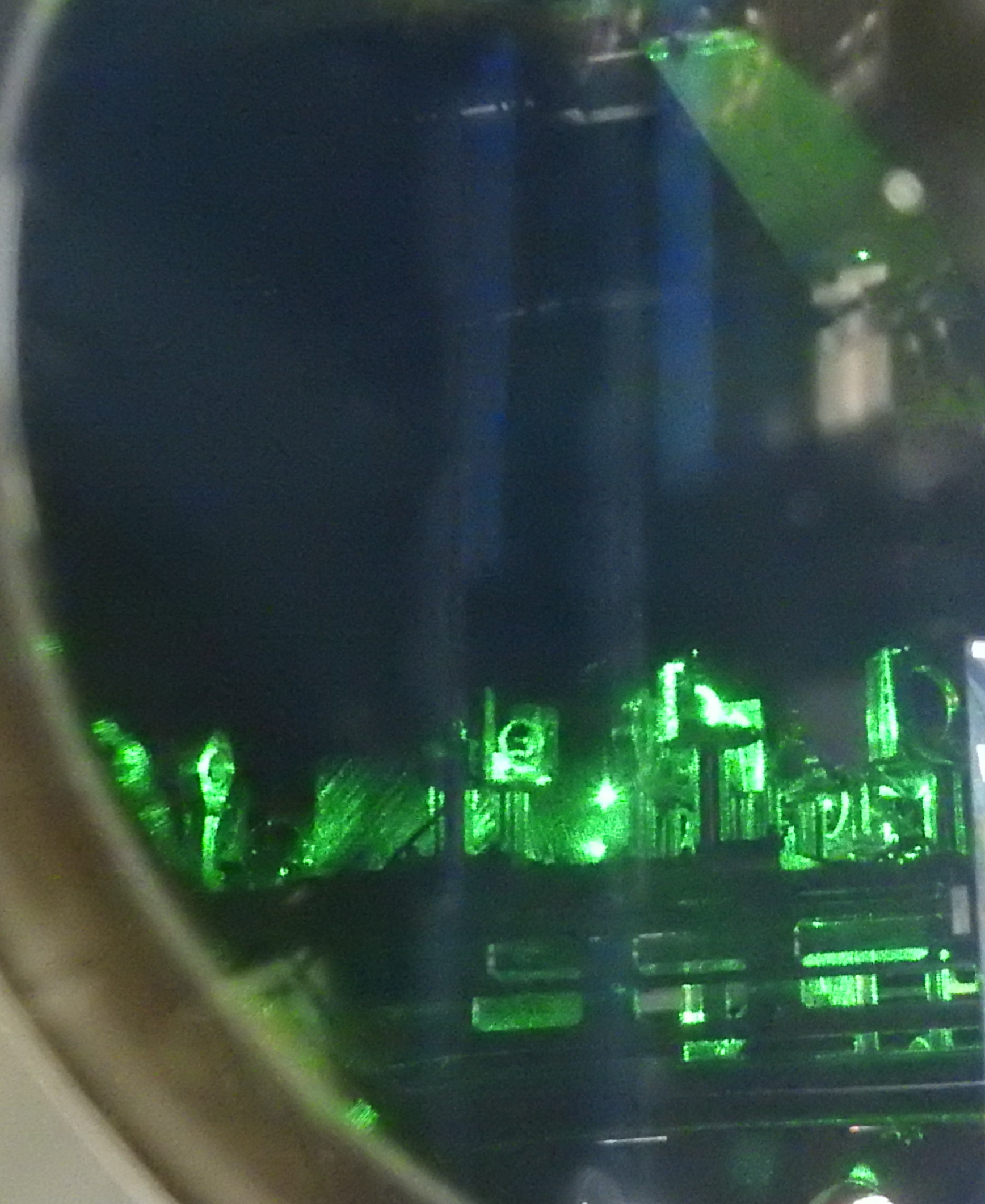
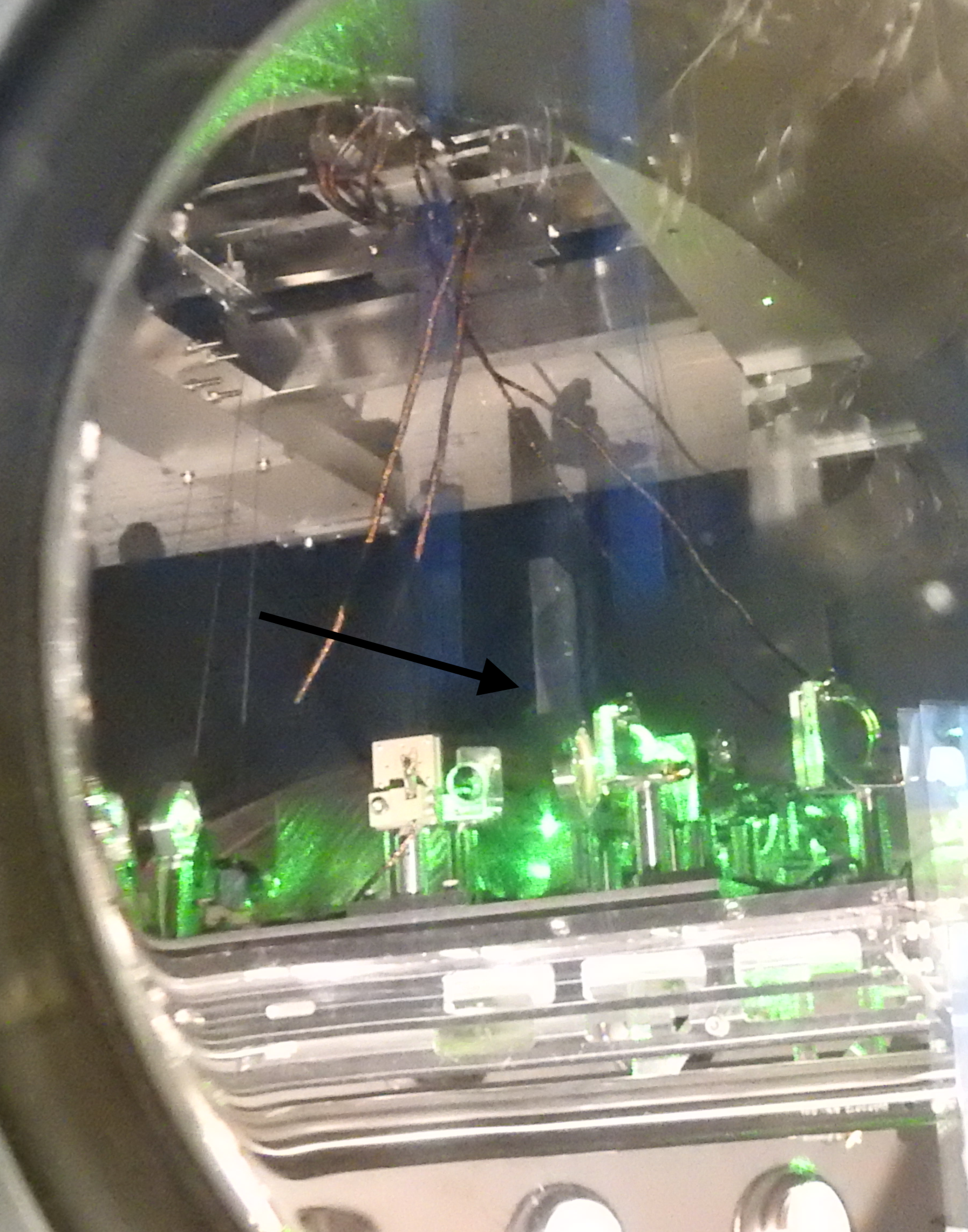
We also took some photos through the illuminator viewport on BSC10, which is just above the camera viewport we took photos through on Friday. This allowed us to see more of the optics on top of the transmission monitor. The beams on the optics that we saw looked ok. Interestingly there is a beam hitting on a mechanical structure (visible in the third, fourth, fifth attachments). Adding a flashlight to the camera viewport, Keita identified this an obsolete HWS periscope. Maybe I'm missing it but I can't find the structure on the TMS assembly drawings. Based the location of the structure relative to the beam path (we think it is behind M6 in this layout diagram) we do not think this clipping beam is the main ALS beam, but it's not obvious which beam is hitting this structure.


Images attached to this report
Comments related to this report
georgia.mansell@LIGO.ORG - 12:48, Wednesday 23 October 2019 (52649)

I had a look back through the alog and found these great pics Corey took of the TMS in 2014. Based on the 5th photo we've had the beam hitting the structure since at least O1, and back then the y arm green mode matching wasn't an issue, so this probably isn't the problem.

keita.kawabe@LIGO.ORG - 12:51, Wednesday 23 October 2019 (52650)

> Maybe I'm missing it but I can't find the structure on the TMS assembly drawings.

First page of ISC TMS drawing (D1000484) marked as "first article". We have never made a "production" unit for TMSY despite the drawing suggesting otherwise. We chose not to remove HWS periscope due to significant rebalancing concern.

There are some pictures showing the Hartman periscope without the mirror holder on top, the latest one I was able to find is from Arnaud's alog back in 2014 (the picture is this one).

LHO VE
kyle.ryan@LIGO.ORG - posted 18:44, Tuesday 22 October 2019 (52634)
YBM turbo installation -> Found 2 x 10⁻⁸ torr*L/sec leak (helium) at the rotatable turbo fixation/6-way cross joint

Gerardo M., Kyle R.

Bummer!  We were so close!  We'll start the day tomorrow addressing this leak. 

LHO VE (VE)
gerardo.moreno@LIGO.ORG - posted 18:42, Tuesday 22 October 2019 - last comment - 19:03, Tuesday 22 October 2019(52633)
Old YBM Turbo Pump and Stand

Separated the turbo from the stand and moved each component over the beam tube.  The turbo pump cart is near the large access door, and the stand is inside the high bay area, for the moment.

Comments related to this report
chandra.romel@LIGO.ORG - 19:03, Tuesday 22 October 2019 (52635)

Please label this unit. I forgot to label the XBM turbo which is "vibey" and may have lost track of its location wrt  old vertex turbo (matters in case we need to reuse). If they have govt tags then we should be good. 

LHO VE (VE)
gerardo.moreno@LIGO.ORG - posted 18:37, Tuesday 22 October 2019 (52632)
Activation of NEG#2 and NEG#3

Unscheduled activation of NEG#2 and NEG#3, all required items to do the activation were near.  No issues were encountered during the activation process for both NEG pumps.


H1 CDS (DAQ)
david.barker@LIGO.ORG - posted 14:17, Tuesday 22 October 2019 - last comment - 08:37, Wednesday 23 October 2019(52626)
CDS Maintenance Summary, Tuesday 22nd October 2019

New BSC ISI, SEIPROC and CALCS models

Jenne, Jim, Dave:

New models were installed for h1isiitmx, h1isibs, h1isiitmy, h1seiproc, h1calcs. A DAQ restart was required.

WP8309 Removal of temporary TCS fast channels

Dave:

I modified TCS_MASTER.mdl to remove the eight temporary 2kHz channels for the CO2_QPD_B segments (four segments for each itm). DAQ restart was required

DAQ Restart

Dave:

I restarted the DAQ for today's model changes. We thought about adding the new BRS-EX and EY channels but ran out of time for today's restarts.

WP8435 DMT OS upgrade, Scientific Linux 7.7

Greg:

Upgrading the OS on the production machines h1dmt[0,1,2]. Note that h1dmt3 (test machine) was upgraded some weeks ago.

Comments related to this report
david.barker@LIGO.ORG - 08:37, Wednesday 23 October 2019 (52644)

mid afternoon we had one more round of h1seiproc model changed followed by  a DAQ restart.

H1 CDS (SEI)
filiberto.clara@LIGO.ORG - posted 11:25, Thursday 17 October 2019 - last comment - 13:14, Wednesday 23 October 2019(52542)
EY BRS Heater Installation

WP 8382

All cabling for the BRS Heater installation have been pulled at EY. Will need help from SEI group for access to the BRS enclosure to finish 24V power and beckhoff network connections.

Comments related to this report
filiberto.clara@LIGO.ORG - 13:14, Wednesday 23 October 2019 (52651)

EY cabling complete.

Displaying reports 37981-38000 of 89075.Go to page Start 1896 1897 1898 1899 1900 1901 1902 1903 1904 End