
kyle.ryan@LIGO.ORG - posted 18:59, Friday 11 October 2019 (52439)
Installed HAM6 East door
Corey G., Bubba G., Kyle R.
Corey G., Bubba G., Kyle R.
Jeff, Sheila, Dan
We got the ok from Chandra to switch on high voltage equipment. We only wanted to switch on the ring heaters though (which are only +-15V so we're not sure why they get switched off?). To switch them on, at the TCS racks (back left corner in the CER) we just flipped the rocker switches on the back of each unit, test masses are now warming up. While we were there we also swtiched the SR3 heater on.
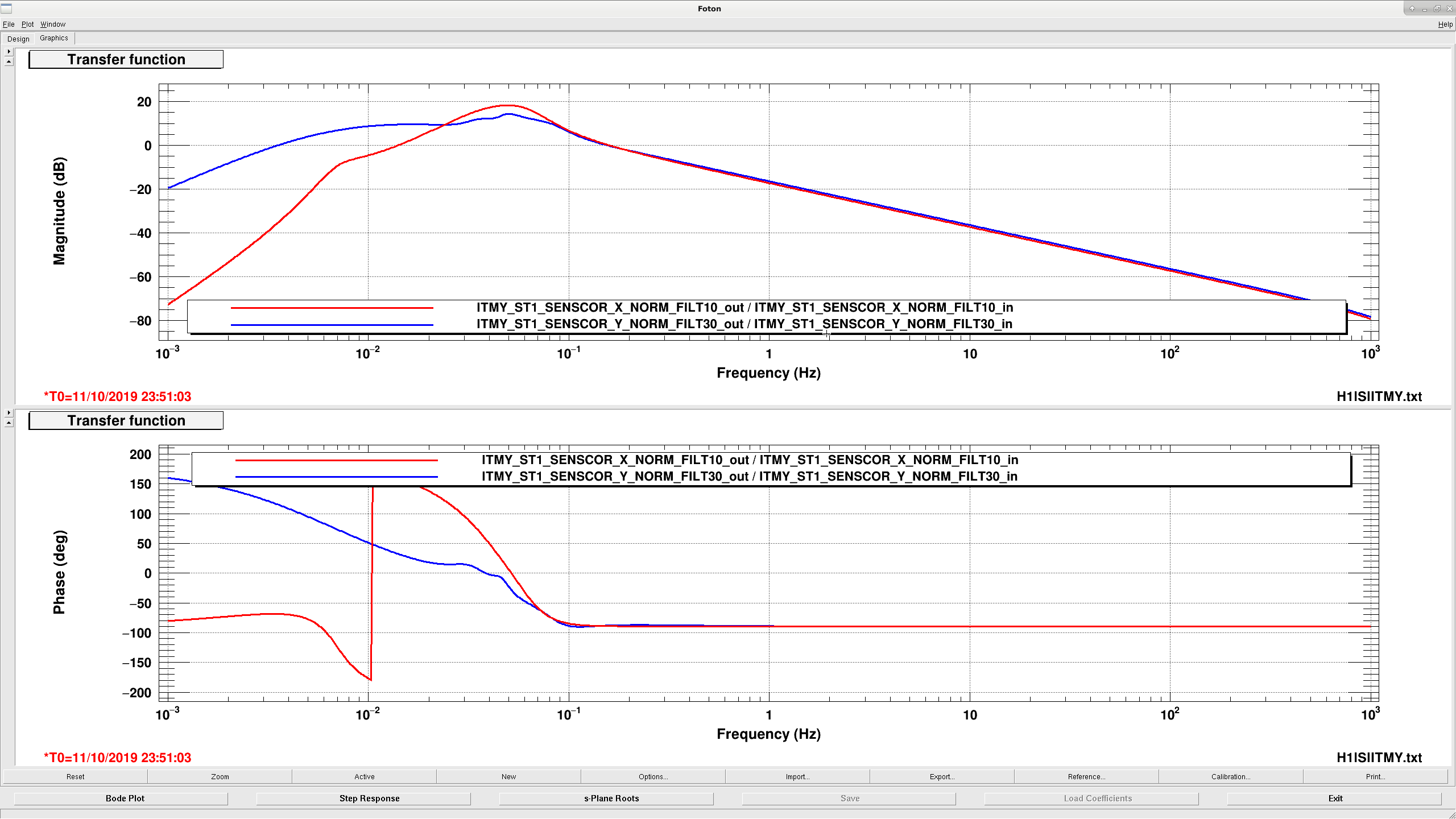
I'm running a sensor correction test on ITMY, using some swarm designed filters from SamC at Birmingham. This is currently engaged in a SEI_CONF state called TEST_SWARM, which is state number 101. Given the state of the BRSes (BRSX was driven out of range at the beginning of Oct, BRSY is getting close), we should not use any states that rely on these sensors, so if it looks like it is necessary to revert my sensor correction test SEI_CONF should be switched to either VERY_WINDY or SC_OFF. If there are any questions about getting back to a normal state, my phone number or email is probably around somewhere.
Attached bode plot shows the new filter in blue compared to the nominal filter in red.
TITLE: 10/11 Day Shift: 15:00-23:00 UTC (08:00-16:00 PST), all times posted in UTC
STATE of H1: Planned Engineering
INCOMING OPERATOR: Niko
SHIFT SUMMARY:
LOG:
14:50 Corey out to LVEA for pics at HAM6
15:47 Jeff takinfg TFs of suspensions
15:48 Corey back from HAM6
15:56 Chub and Jordan to MX
16:07 Chandra out to LVEA - Xmanifold turbo pump
16:08 Jim in LVEA unlocking HAM6 ISI
16:27 Sheila and Besty out to HAM6
16:32 Niko ad Dripta out to EY for PCal
16:34 Sheila and Betsy back
16:43 Jeff J, Timesh into optics lab
16:44 Jim back
16:53 EY is LASER HAZARD - PCal
17:11 Richard and co. to out buildings
17:15 Travis out to LVEA
17:20 Sheila out to HAM6 area to transition to laser hazard
17:25 Squeezer area is now laser hazard
17:26 Corey, Gavin, and Phillipe out to EY
17:58 Richard and co. back
18:01 Timesh and Jeff J back
18:05 Corey back
18:08 Travis back
18:18 EY is now LASER SAFE
18:28 Phillipe and Gavin back
18:29 Dan and Cao out to optics lab
18:41 Sheila, Nuts, and TJ out to HAM6
18:59 Betsy out to HAM6
19:49 Hugh and Richard to Ends
19:56 Sheila called with intent to transition back to laser safe for HAM6 area
19:59 Squeezer area is LASER SAFE
22:30 LVEA transitioned to LASER HAZARD
Chandra, Dave:
The alarm levels we set several days ago are now being approached. I have increased the alarm levels on both PT144B (X1 beam tube, corner station end) and PT343B (X1 beam tube, MX end) to 5.0e-08Torr for the weekend.
+<Channel name="H0:VAC-LX_X4_PT144B_PRESS_TORR" low="1.0e-10" high="5.0e-08" description="VE gauge, LX X1-beamtube, CC">
+<Channel name="H0:VAC-MX_X1_PT343B_PRESS_TORR" low="1.0e-10" high="5.0e-08" description="VE gauge, MX X1-beamtube, CC">
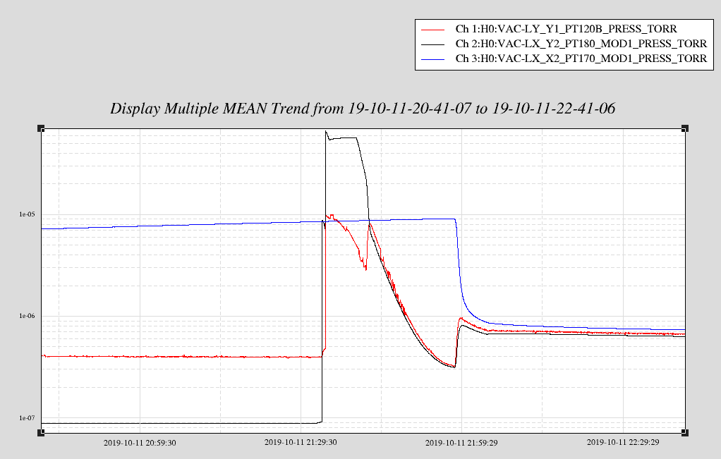
Slowly opened GV1 and then GV2 to combine the vertex with YBM and XBM volumes. Accidentally burped in dry purge air from GV1 gate annulus because outer o-ring leaks (when vertex was vented) and this caused YBM turbo to trip and YBM pressure to rise to e-5 Torr. YBM turbo is now spun down and scroll off; vertex turbo is pumping the entire corner station, backed by scroll. Shut down QDP80 and flushed header with purge air.
J. Kissel, R. Kumar, T. Shaffer

After debugging the SQZ green fiber one more time (see LHO aLOG 52420), we were given 30 minutes to make an assessment of all 6 suspensions in HAM6. We were able to gather all DOFs of all suspensions, and they all look as free of rubbing as one can tell from an in-air measurement. We are OK for doors.

Eventually we will analyze the data in full and compare against previous (or maybe not, we may just wait until we have measurements of the SUS under full hard vacuum and with the SEI system is its nominal observing state).

The hardest to measure continues to be the OPOS, the suspension platform for the in-vacuum OPO system for the squeezer. I've found an in-air configuration that works well enough to assess the health, and give more details below.
For all other suspensions we were able to just open up the template, turn off the damping loops, and hit "go" getting wonderfully clean measurements (all coil drivers for each SUS in HAM6 are either forced to have only one configuration [the OPOS, OMs and ZM1], or is always left in its highest noise state [the OMC].).

% Measurement Details:
In order to gather acceptable data on the OPOS while it was in-air, on a damped ISI and locked HEPI:
    (1) Turn the purge air down, if allowed (Thanks Betsy!)
    (2) The OPOS does not have switchable coil driver states, and it's fixed in its lowest noise state (see T1700434), so the coil driver request must remain in State 2.
    (3) For all the DOFs you're *not* measuring, leave the damping loops ON. (this necessarily means you'll have less fundamental cross-coupling in multi-DOF modes, like the L and P modes)

Also, I've re-tuned the amplitude / frequency response of the drive excitation to have much more drive at the resonances, and less gain at low frequency, and a jacked up overall gain. Some of the templates will "saturate the DAC" according to the front-end model's CDS BIT WORD, but ASDs of the MASTER OUT channels from each OSEM DOF show that the RMS of the requested drive at all frequencies is less than (2^15 ct_pk) * (1 ct_rms / sqrt(2) ct_pk) = 23170 ct_rms, where 2^15 is the peak value allowed for the OPOS 16-bit DAC (it's likely that -- because of the poor normalization of the digital AA filters that upsample from the OPOS model rate of 16384 Hz to the native IO chassis rate of 65536 Hz -- there's a ~10% amount of gain peaking that amplified the signal at many kHz, and thus saturating the DAC at those frequencies. Blah blah blah there may be some level of non-linear effects going on but the magnitude, phase, and coherence look good enough to assess an "are the dynamics OK" answer.)

As a tease, I attached one DOF (pitch to pitch) of the OPOS to show you the kind of data quality I'm able to get after all of the above.

Those new templates live here:

/ligo/svncommon/SusSVN/sus/trunk/OPOS/H1/OPO/SAGM1/Data/
    2019-10-11_2025_H1SUSOPO_M1_WhiteNoise_L_0p02to50Hz.xml
    2019-10-11_2025_H1SUSOPO_M1_WhiteNoise_P_0p02to50Hz.xml
    2019-10-11_2025_H1SUSOPO_M1_WhiteNoise_R_0p02to50Hz.xml
    2019-10-11_2025_H1SUSOPO_M1_WhiteNoise_T_0p02to50Hz.xml
    2019-10-11_2025_H1SUSOPO_M1_WhiteNoise_V_0p02to50Hz.xml
    2019-10-11_2025_H1SUSOPO_M1_WhiteNoise_Y_0p02to50Hz.xml

The data for all other suspensions in HAM6 live in the following directories:
/ligo/svncommon/SusSVN/sus/trunk/HTTS/H1/
    OM1/SAGM1/Data/
        2019-10-11_2000_H1SUSOM1_M1_WhiteNoise_L_0p02to50Hz.xml
        2019-10-11_2000_H1SUSOM1_M1_WhiteNoise_P_0p02to50Hz.xml
        2019-10-11_2000_H1SUSOM1_M1_WhiteNoise_Y_0p02to50Hz.xml

    OM2/SAGM1/Data/
        2019-10-11_2000_H1SUSOM2_M1_WhiteNoise_L_0p02to50Hz.xml
        2019-10-11_2000_H1SUSOM2_M1_WhiteNoise_P_0p02to50Hz.xml
        2019-10-11_2000_H1SUSOM2_M1_WhiteNoise_Y_0p02to50Hz.xml

    OM3/SAGM1/Data/
        2019-10-11_2000_H1SUSOM3_M1_WhiteNoise_L_0p02to50Hz.xml
        2019-10-11_2000_H1SUSOM3_M1_WhiteNoise_P_0p02to50Hz.xml
        2019-10-11_2000_H1SUSOM3_M1_WhiteNoise_Y_0p02to50Hz.xml

    ZM1/SAGM1/Data/
        2019-10-11_2000_H1SUSZM1_M1_WhiteNoise_L_0p02to50Hz.xml
        2019-10-11_2000_H1SUSZM1_M1_WhiteNoise_P_0p02to50Hz.xml
        2019-10-11_2000_H1SUSZM1_M1_WhiteNoise_Y_0p02to50Hz.xml

/ligo/svncommon/SusSVN/sus/trunk/OMCS/H1/OMC/SAGM1/Data/
    2019-10-11_2045_H1SUSOMC_M1_WhiteNoise_L_0p02to50Hz.xml
    2019-10-11_2045_H1SUSOMC_M1_WhiteNoise_P_0p02to50Hz.xml
    2019-10-11_2045_H1SUSOMC_M1_WhiteNoise_R_0p02to50Hz.xml
    2019-10-11_2045_H1SUSOMC_M1_WhiteNoise_T_0p02to50Hz.xml
    2019-10-11_2045_H1SUSOMC_M1_WhiteNoise_V_0p02to50Hz.xml
    2019-10-11_2045_H1SUSOMC_M1_WhiteNoise_Y_0p02to50Hz.xml

All HAM6 HTTSs are processed, results attached. All of them look free and match the results from our last closeout in Nov 2018.
Here're the comparisons between the above mentioned measurement of the H1SUSOPO vs. previous measurements. As described above, the results are ratty and poorly coherent w.r.t. an in vacuum measurement, but if you blur your eyes and hope, the suspension appears free.

Attached are the usual kind of plots -- comparing the individual measurement against the model (2019-10-11_2025_H1SUSOPO_M1_ALL_TFs.pdf), and then a comparison between several measurements of this and other suspensions against model (
alloposs_2019-10-11_H1SUSOPOS_OPO_Phase3a_UnDamped_ALL_ZOOMED_TFs.pdf).

For the first attachment, all the cross degrees of freedom and OSEM basis DOF measurements are all non-sensical because we don't have enough actuation strength to characterize these in air.
The second attachment, in this case, is probably the mode useful.

BUT -- we should repeat these measurements once doors are fully on and we've got some respectable vacuum in the system to really confirm that this SUS is truly OK.

Processed by
/ligo/svncommon/SusSVN/sus/trunk/OPOS/Common/MatlabTools/
    plotOPOS_dtttfs_M1.m
    plotallopos_tfs.m
which have been committed to the svn.
I've processed the H1SUSOMC, and all looks quite well. The only issue is some poor data quality on the V to V transfer function, but I'm confident this is just noise and nothing wrong with the suspension.

Data processed by:
/ligo/svncommon/SusSVN/sus/trunk/OMCS/Common/MatlabTools/
    plotOMCS_dtttfs.m
    plotallomcs_tfs.m
Nutsinee, Sheila, TJ, Daniel, Betsy
Main message: Both the squeezer fibers are working OK now, although the red transmission was very low earlier today it is reasonable again after a few rounds of disconnecting the in air fiber from the feedthrough.
More details:
After Jim adjusted the fiber routing to avoid rubbing issues on the ISI 52419, we went to laser hazard in the squeezer bay to check that the fiber transmissions are OK one last time before closing HAM6.
Green fiber 39% transmission through the entire chain
Red fiber was bad, is now 25-33% total transmission
We noticed that the transmission of the entire red chain was bad:
{Kyle, Chandra}
Spun up new ATH2303 turbo at mid-x at ~ 100 mTorr, backed by QDP80. Turbo came to full speed within 10 minutes and pressure fell to low e-6 Torr range quickly. Leak checked the spool side of turbo GV and IP10 GV; both leak tight with LD background < 1e-9 Torr-L/s.
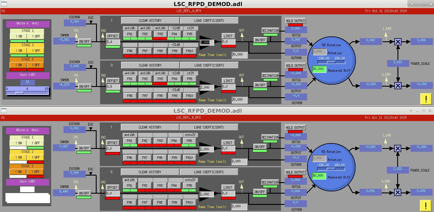
Comparing the REFL readback signals from this morning, where there is NO light on the REFL PDs, to a time when we are locked, it seems that the REFL B readout could benefit from some additional whitening.
In fact, it seems all readbacks would benefit.
REFL B is not hooked up to a usual ADC chassis, according to Daniel.  It's not so simple to put in additional whitening.
REFL A is hooked up to the usual three stages of (z=10 Hz, p=1 Hz) whitening, and two stages of whitening are currently being used.  Unclear if we would saturate the ADC if we turned the final stage on.
REFL ERR has NO whitening, it's actually just a -60 dB gain, despite the name in the filter module.

Also, both H1:LSC-REFL_A_RF9_I_ERR_DQ and H1:LSC-REFL_B_RF9_I_ERR_DQ are saved at 2048 samples per second.  Would surely be beneficial to bump this up to 16 kHz.
Rahul, Chiara, Jeff B.

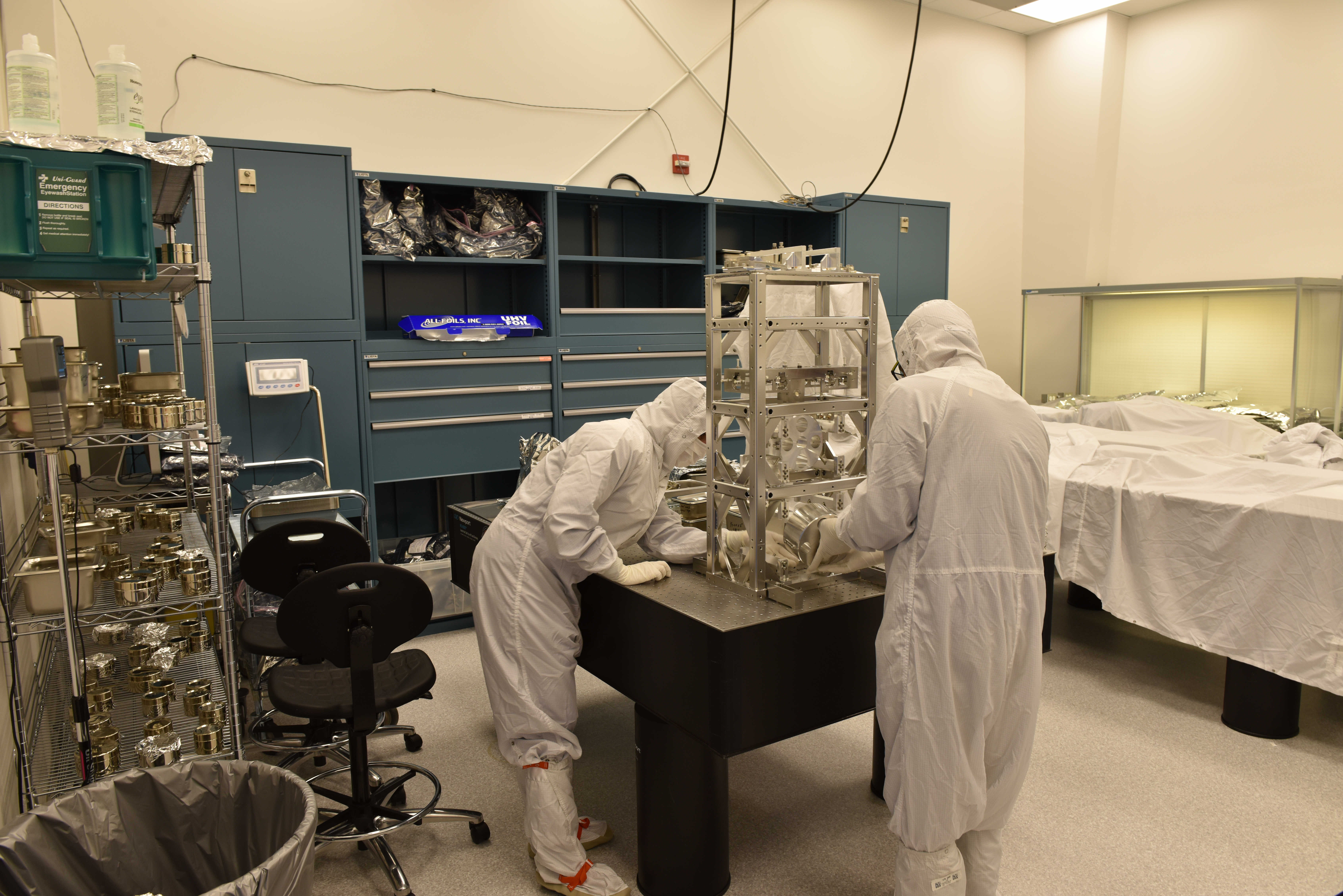
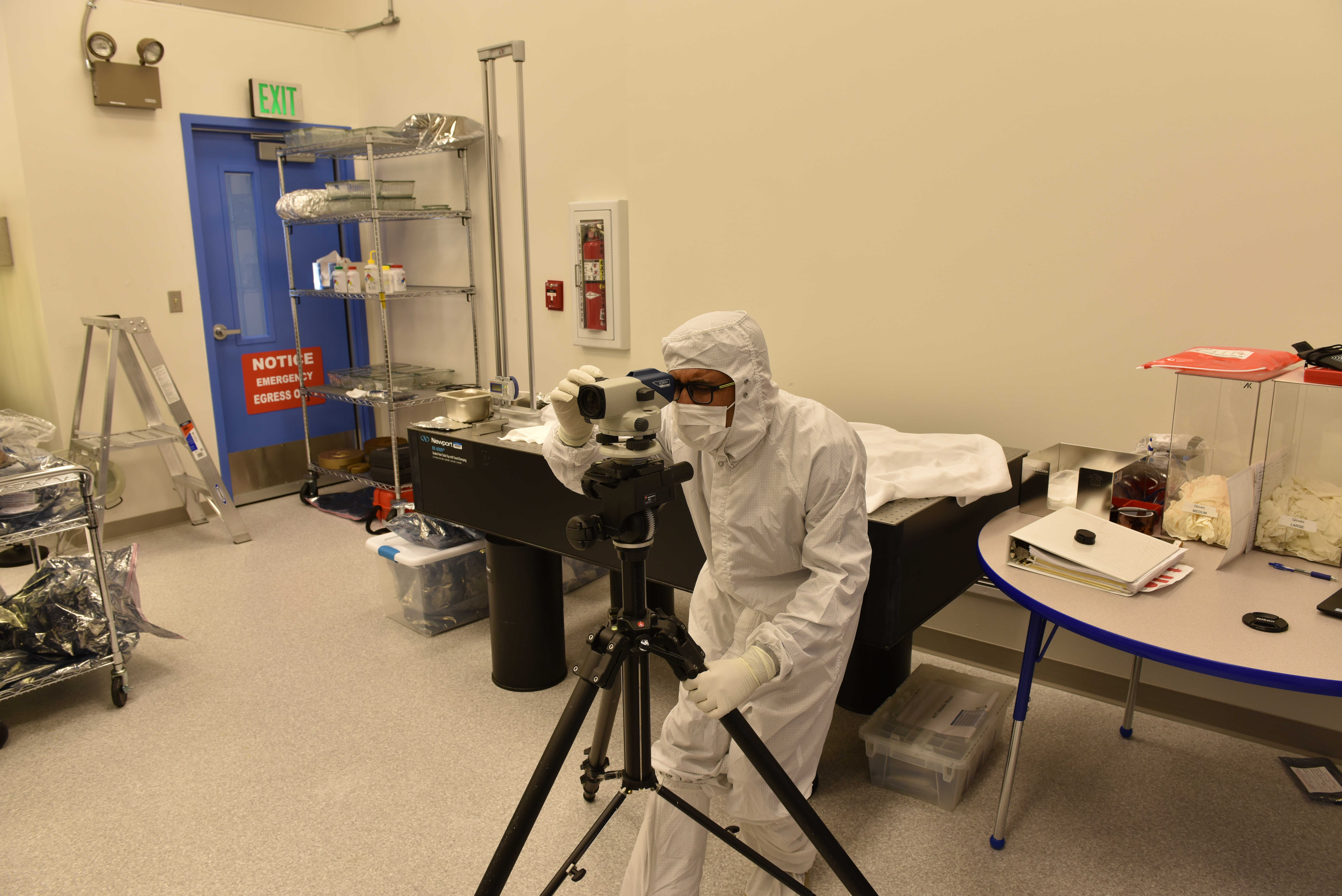
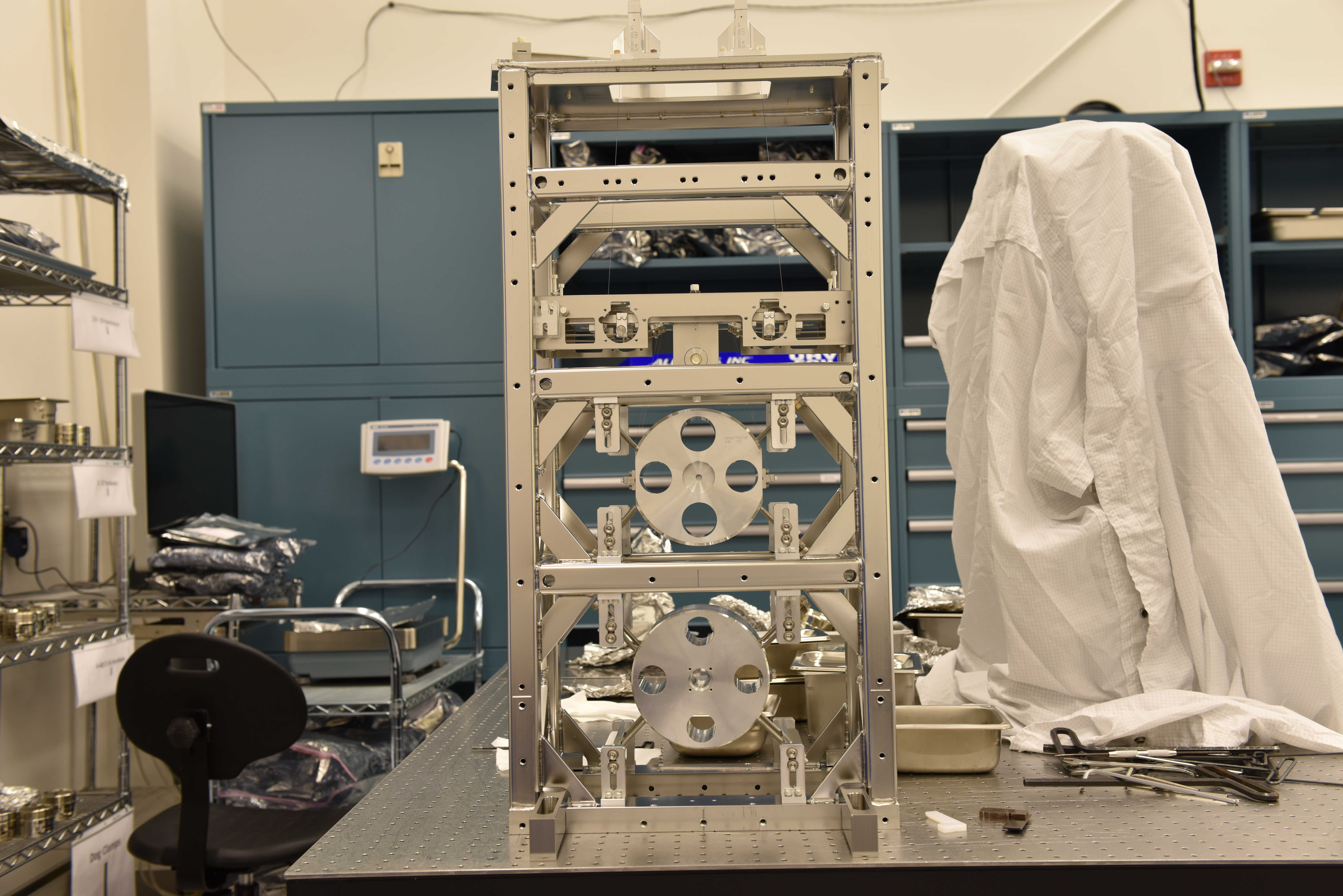
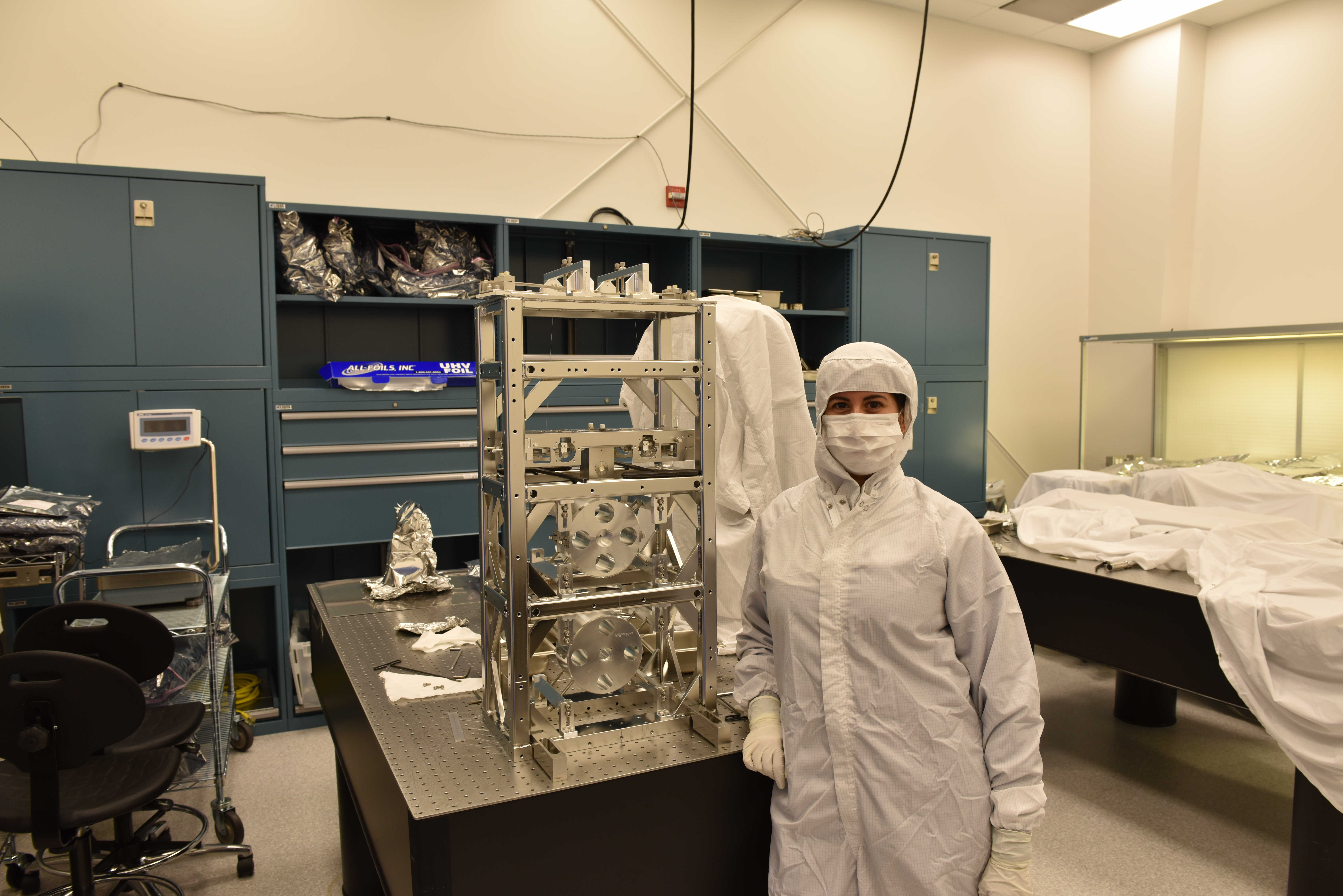
   This morning the SUS assembly team install the Bottom Mass into the FC1 Suspension, completing the first phase of the assembly. Due to my clumsy hands, I broke one of the lower wires. There was not enough time to build another wire and install it before the other members of the team were called away for the close out of HAM6 and meetings.

   A new has been pulled and is ready to install. With the wire is installed, we start the second phase of balancing and alignment.

   The FC2 Top Mass is installed. The installation of the Intermediate and Bottom Masses is scheduled for early next week.
J. Kissel, R. Kumar

Since we really have no precedent for "which suspensions do we check for rubbing when after what level of vent activity?" Rahul and I are refreshing our memory on how to take rubbing check transfer functions on the SUS in HAM5.

I've gathered data for SUS SRM, the data look OK -- good enough to proceed.
I see several things of which I'm suspicious about, but will then proceed to wave my hands around and explain away what I think is going on, and or why it'll be good enough.
Take a look primarily at the second attachment, allhstss_2018-10-11_H1SUSHSTS_SRM_Phase3b_UnDamped_ALL_ZOOMED_TFs.pdf.
(1) In all DOFs, the data looks a bit noisy for a SUS that is under vacuum. BUT -- the HAM5 ISI is only "damped" not fully isolated, HAM5 HPI is still locked, and the adjacent, HAM6 chamber is open with full purge going and people in it actively debugging the SQZ green fiber. So, I expect that things will still be a bit noisy. We can still resolve primary and cross-coupled resonances, so we can still assess the dynamics.
(2) In all DOFs, the overall scale of the transfer functions seem to be gradually dropping over the *years*. I suspect that this a result of the OSEM LED decay over time, which is a known issue on most-if-not-all-suspensions that we won't be doing anything about for quite some time. See FRS 10093
(3) In several DOFs, there appears to be more cross coupling than the model, or the previous, fully-isolated, fully-vacuumed, measurement. E.g. in the L2L TF, at 2.078 Hz, or T2T TF, at 2.234 Hz, or in the Y2Y TF, at 2.812 Hz. There are several reason we can use to say "meh -- good enough."
    (a) The all of the "primary" resonances, in the diagonal degrees freedom line up nicely with the model and previous measurements.
    (b) Where we do see the smaller, cross-coupling, resonances in one diagonal TF, they line up well with the primary resonances of other TFs degrees of freedom.
    (c) The DOFs which are cross-coupling together are DOFs that we expect to cross couple together, either mechanically (e.g. the 2.2354 Hz cross-coupling resonance in T2T is showing the primary R2R mode), or because those DOFs are sensed by the same sensors, just one is common and the other is differential (e.g. the 2.812 Hz mode in Y2Y is the poorly subtracted 3rd primary L2L mode because, say, there's lots on power in the L2L mode, or the sensor gains [i.e. the LEDs] have decayed differently over time).

%% Measurement Details
The raw data live here:
/ligo/svncommon/SusSVN/sus/trunk/HSTS/H1/SRM/SAGM1/Data/
    2019-10-11_1804_H1SUSSRM_M1_WhiteNoise_L_0p02to50Hz.xml
    2019-10-11_1804_H1SUSSRM_M1_WhiteNoise_P_0p02to50Hz.xml
    2019-10-11_1804_H1SUSSRM_M1_WhiteNoise_R_0p02to50Hz.xml
    2019-10-11_1804_H1SUSSRM_M1_WhiteNoise_T_0p02to50Hz.xml
    2019-10-11_1804_H1SUSSRM_M1_WhiteNoise_V_0p02to50Hz.xml
    2019-10-11_1804_H1SUSSRM_M1_WhiteNoise_Y_0p02to50Hz.xml
following the "remember to think about" steps of (now updated) instructions on the awiki: wiki/Suspensions/OpsManual/TFs

I've exported and processed the individual data using:
/ligo/svncommon/SusSVN/sus/trunk/HSTS/Common/MatlabTools/
    plotHSTS_dtttfs_M1.m
and added the individual measurement to the collection of data and processed today's against previous with the plotall script that lives here:
/ligo/svncommon/SusSVN/sus/trunk/HSTS/Common/MatlabTools/
    plotallhsts_tfs_M1.m
remembering that Brett wrote a convenient script to update the reference number of the VERY long list measurements that lives here:
/ligo/svncommon/SusSVN/sus/trunk/Common/MatlabTools/
    plotallsus_index_updater.m
(all were svn up'ed before I got started).
J. Kissel, T. J, Rahul
Attached below are the transfer function results for the SR3 and OFI in HAM5. The results have been compared against past data and they looks to be fine, i.e. tying-up well with the modeled data (although detailed analysis is still pending).
[Keita, Nutsinee, Sheila, Jenne]
We went in to HAM6 today, and believe that we have finished all ISC/SQZ related tasks, and are ready to begin closeout procedures tomorrow. (Betsy, who has the final say, will write an alog or talk to the relevant folks for the actual final start of closeout.)
After Richard opened the PSL shutter and Ed locked the IMC, we pretty easily were able to get beam onto AS_C. To check our alignment, Sheila aligned the Michelson, then made sure we were still centered on AS_C. Since we don't have arms, we just assumed that the input beam is pretty close to its usual, and only adjusted ITMs and BS for MICH. Around this time, Keita noticed that there was a bit of a 'tail' on the beam as seen on an IR card. Sheila walked SR2 and SR3 until the tail was gone, but we were still centered on AS_C. After this we aligned SRY (restored SRM, misaligned ITMX) to get good fringes, so that we could trust the SRM position for squeezer-related work. We also took the IMC offline (which misaligns MC2) to remove the main IFO beam, injected the SQZ beam, ran the squeezer's ASC loops, and noted that the ZM1 actuators were very close to the edge of their ranges (as Sheila made a quick note about in alog 52405). We deferred action on this until after the main IFO path checks were complete.
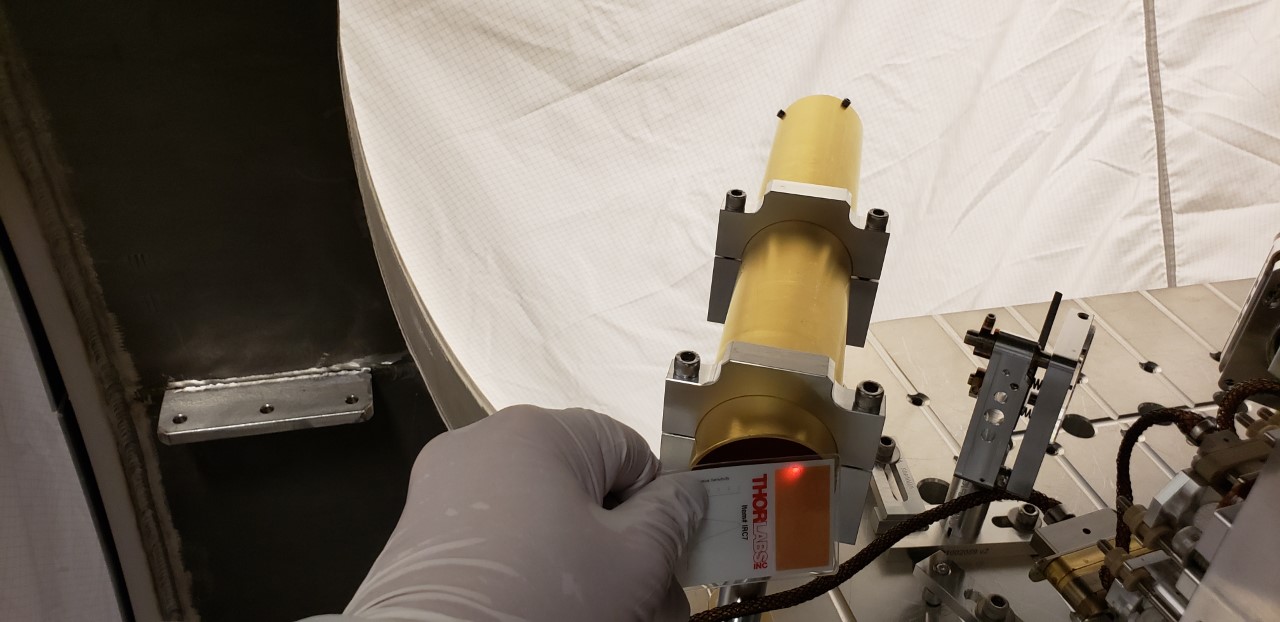
Once we were happy with all of our alignments we brought the main IFO beam back and Nutsinee took photos of the beam in several different places, including the septum window, the position on OM1, the position relative to the fast shutter's wire, the position on OM2, the position going into and returning from the OMC shroud, and some photos to ensure that we don't see any obvious scattered light at the shroud apertures.
Having completed this, and deciding that it was still quite early in the day, we began work on relieving the ZM1 actuator. Sheila noted that the pico that is on/near the OFI is closer in Gouy phase to ZM2 than ZM1, so would not be a satisfactory way of relieving ZM1. Sheila and Keita went in and adjusted the last steering mirror on the VOPO platform that sends the beam to ZM1 about 1/4 of a turn in yaw, clockwise if you are standing at the endcap. After I damped the VOPO we re-ran the squeezer alignment loops, and found that instead of having outputs of nearly 29k the ZM1 outputs were at most about 7k. Excellent! We note that the ZM2 outputs are around 22k, but this is the same that they were during O3a, it hasn't drifted, and if we need to we can relieve ZM2 using the pico, so we are leaving things as-is.
With these 2 sets of checks and work, I believe that we are done with ISC/SQZ work in HAM6. Nutsinee will comment with her photos.
Nice work team!! We'll mobilize to do the chamber unlocking and closeout tomorrow!
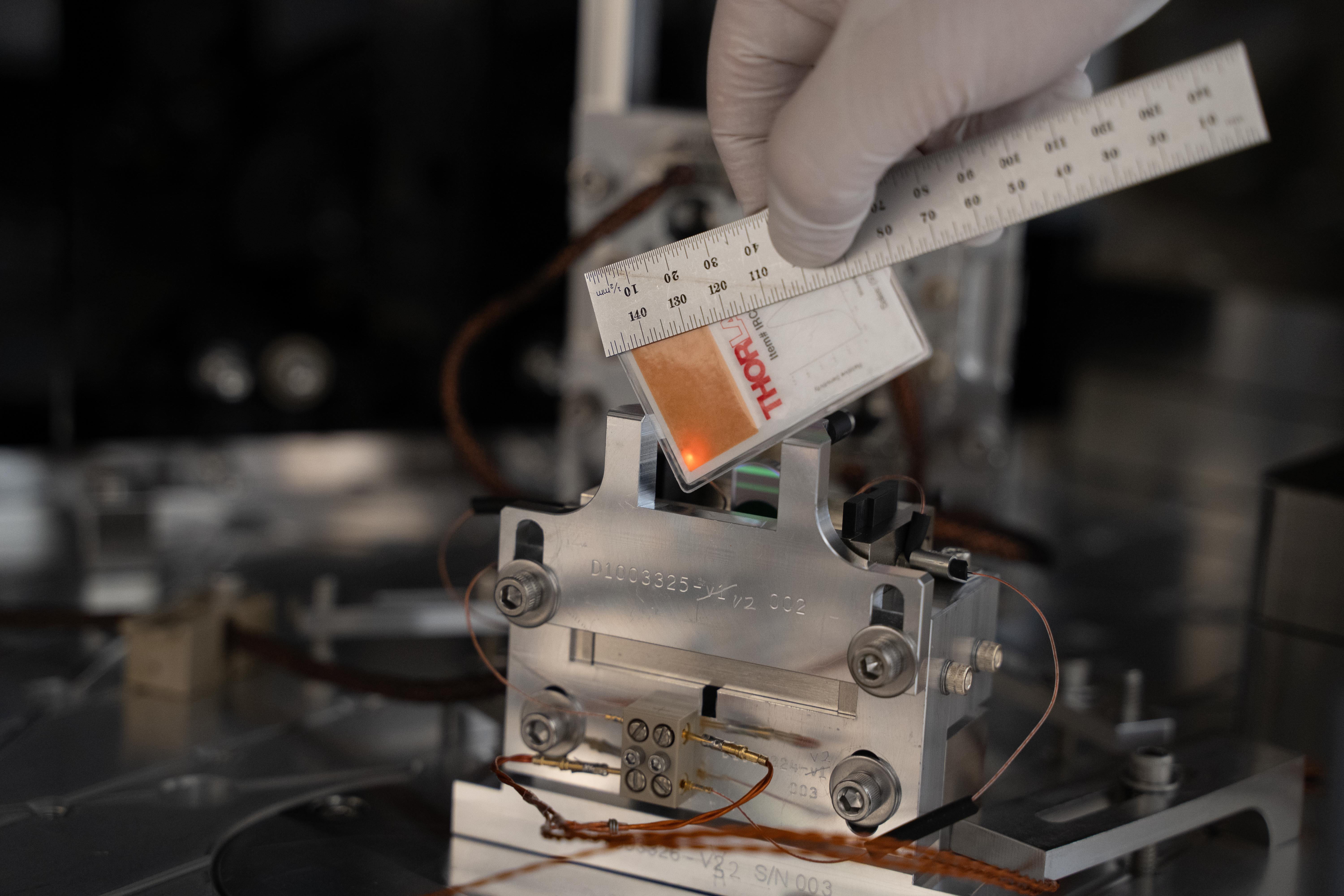
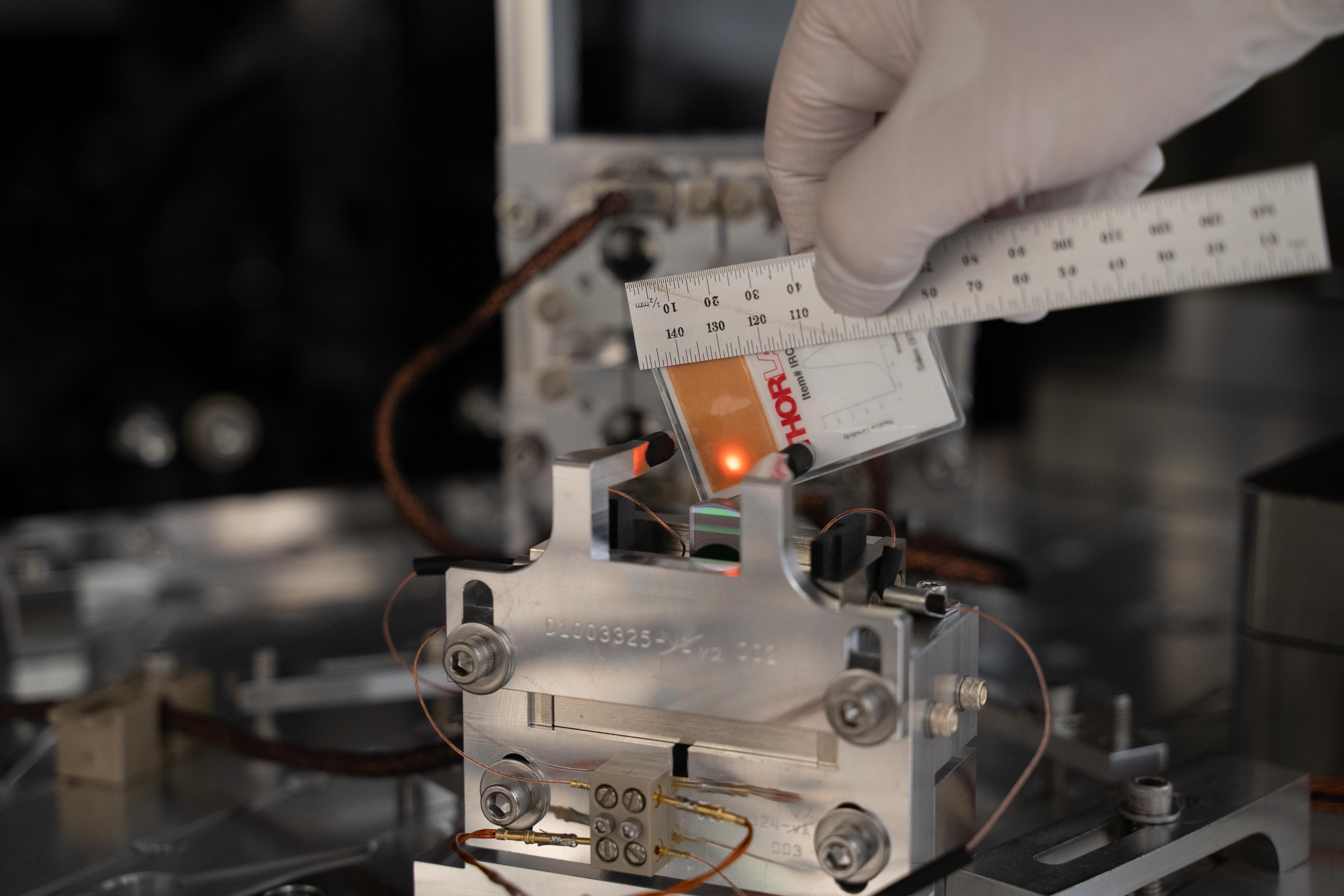
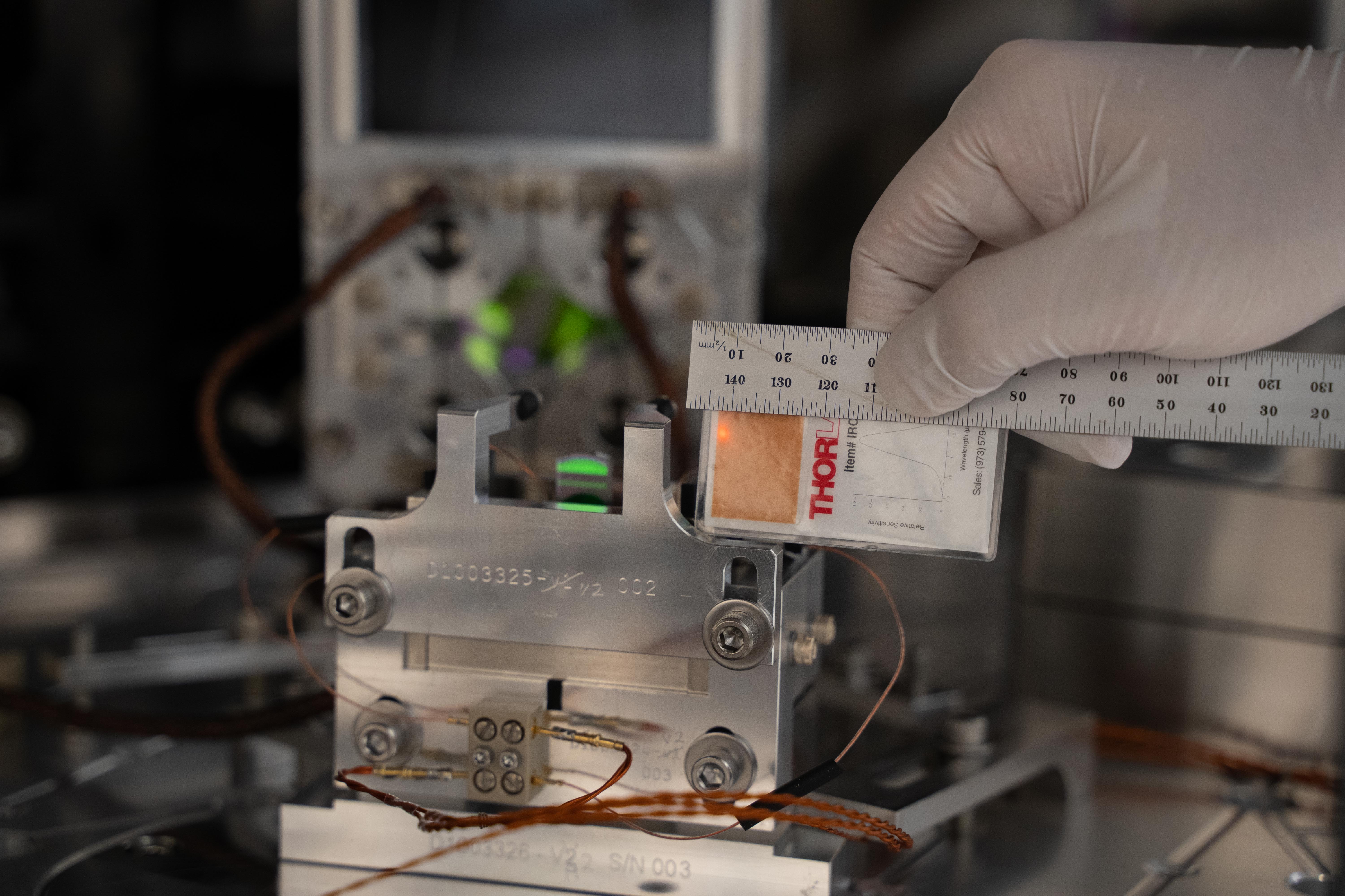
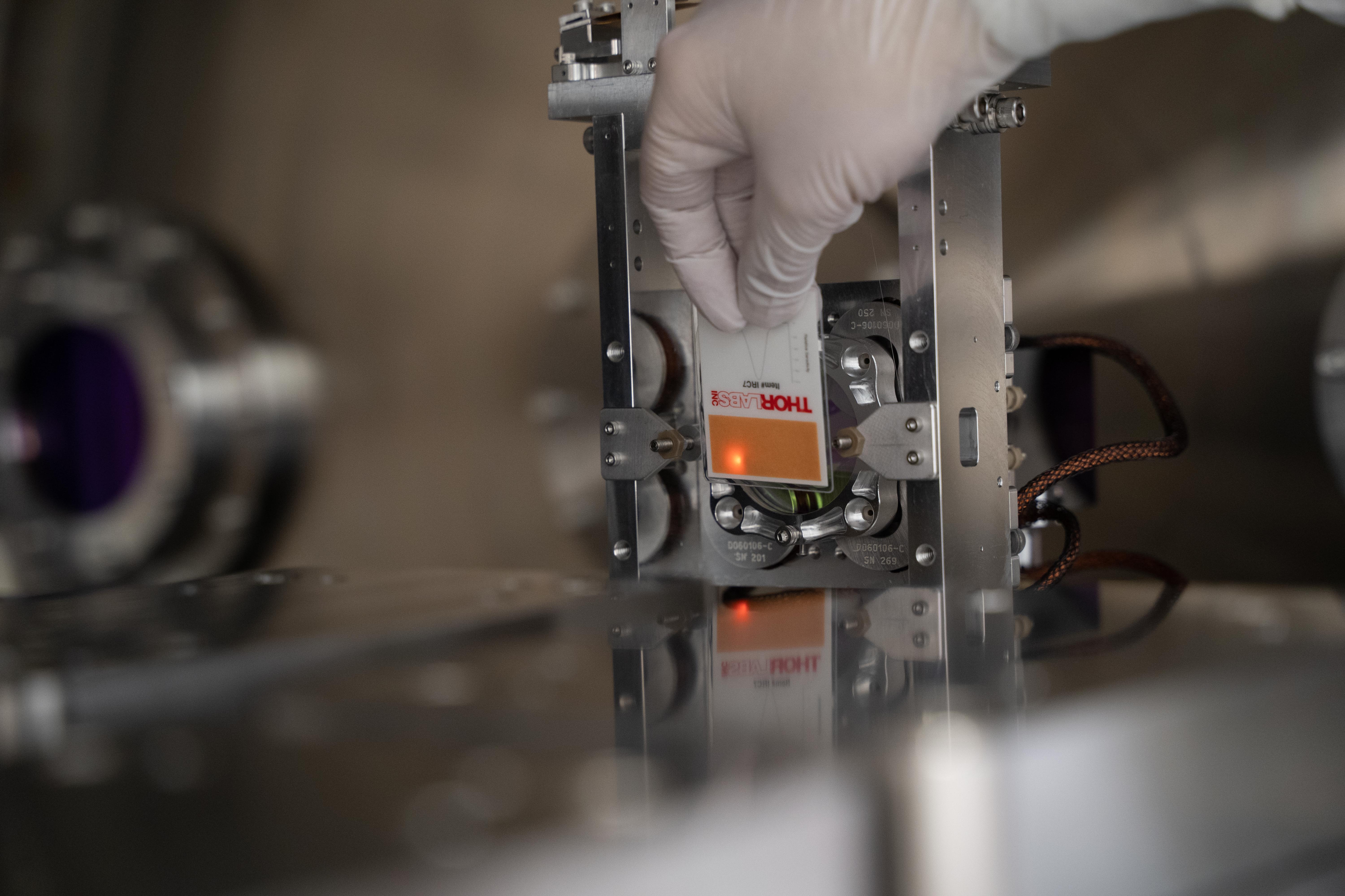
Attached photos of beam at various places.
1) Beam coming out of septum window towards OM1 -- taken as close as possible to the beam height, vertical view
2) Beam coming out of septum window -- camera aligned to the beam as much as possible, horizontal view
3) Beam towards OM1 just before the fast shutter
4) Beam towards OM1 just after the fast shutter
5) Beam reflecting off OM1, in front of the fast shutter
6) Beam reflecting off OM1, behind the fast shutter
7) Beam next to the toaster again after a small alignment change. The beam location stayed pretty much the same.
8) Beam on OM1 (vertical view)
9) Beam on OM1 (horizontal view)
10) Beam on OM2 (vertical view)
11) Beam on OM2 (horizontal view)
12) Beam on OM2 (IR camera)
13) Beam going into OMC, reflects off OM3
14) Beam going into OMC, vertical view
15, 16, 17) OMC input output port area (IR camera looking for scattering)
18) Beam relative to the wire when fast shutter closed
19) OMC refl on beam dump
20) Beam reflects off fast shutter to beam dump
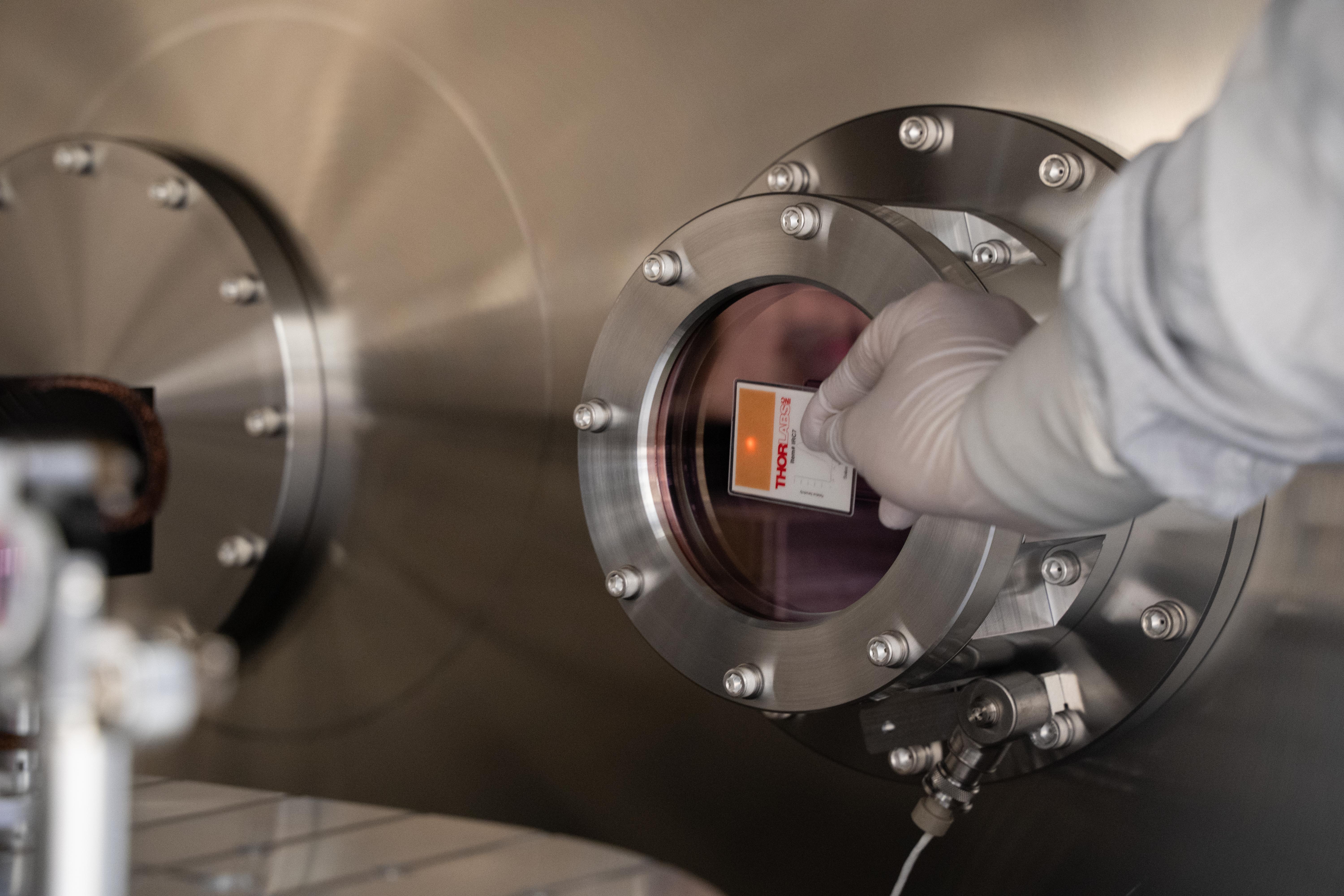
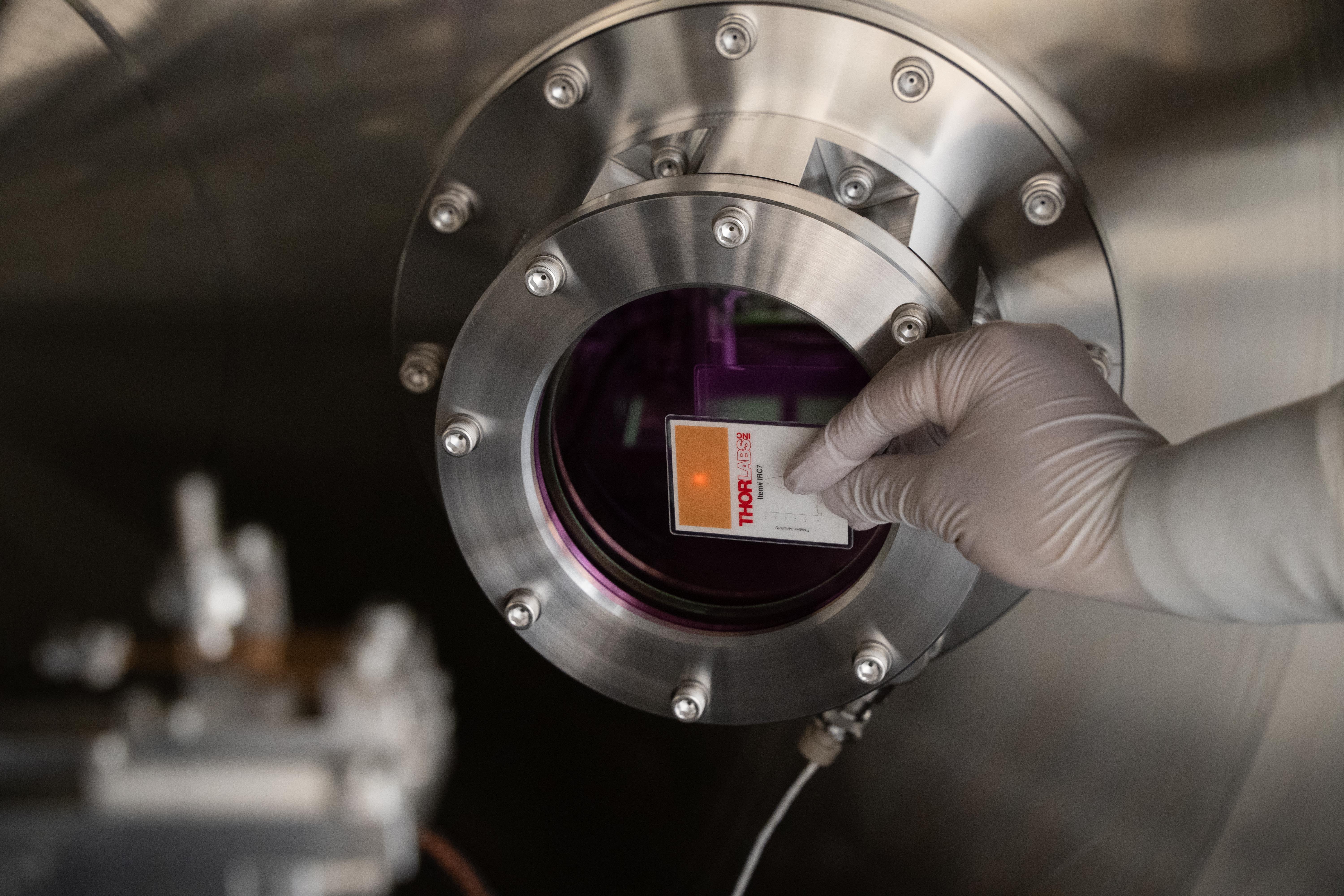
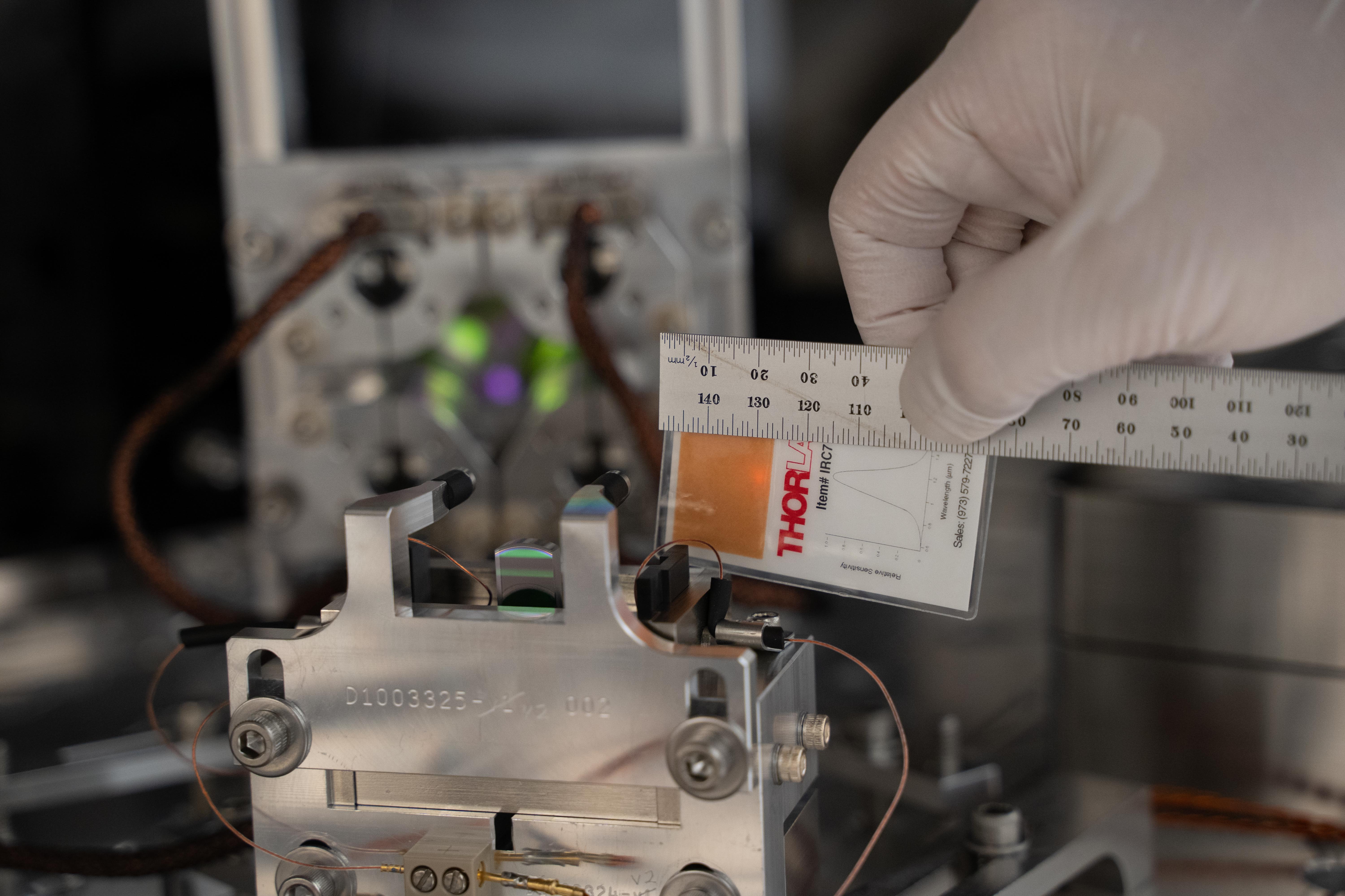
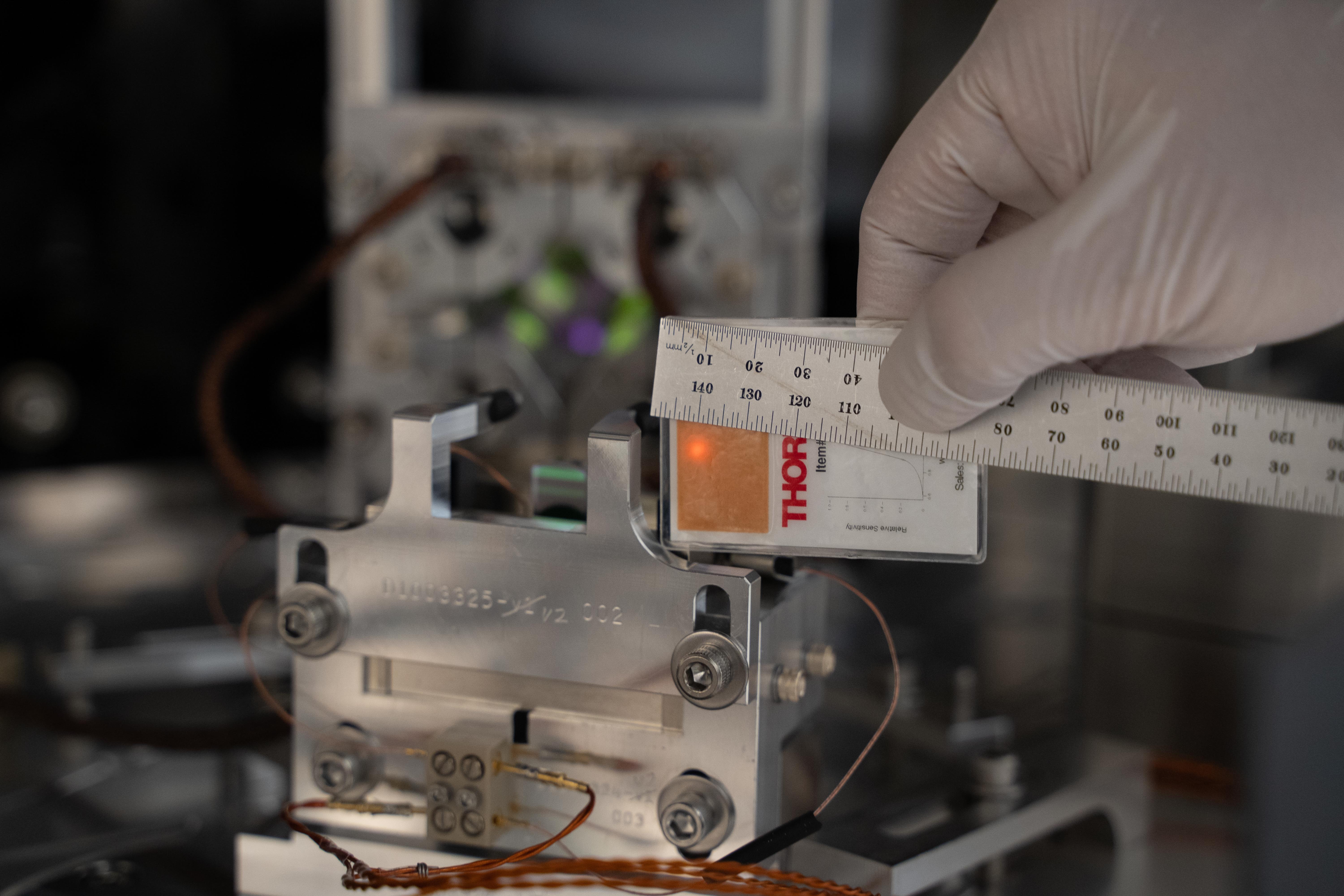


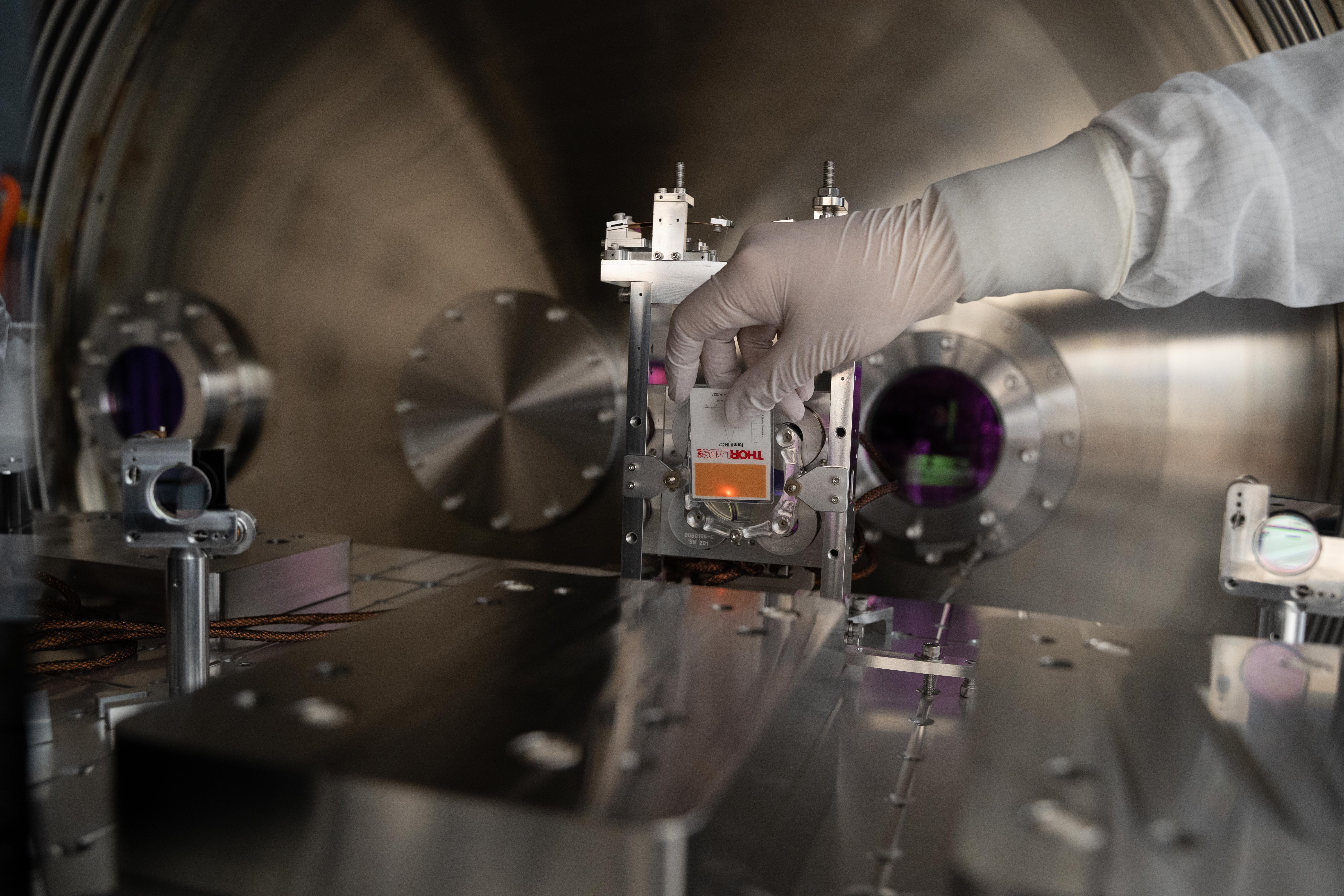
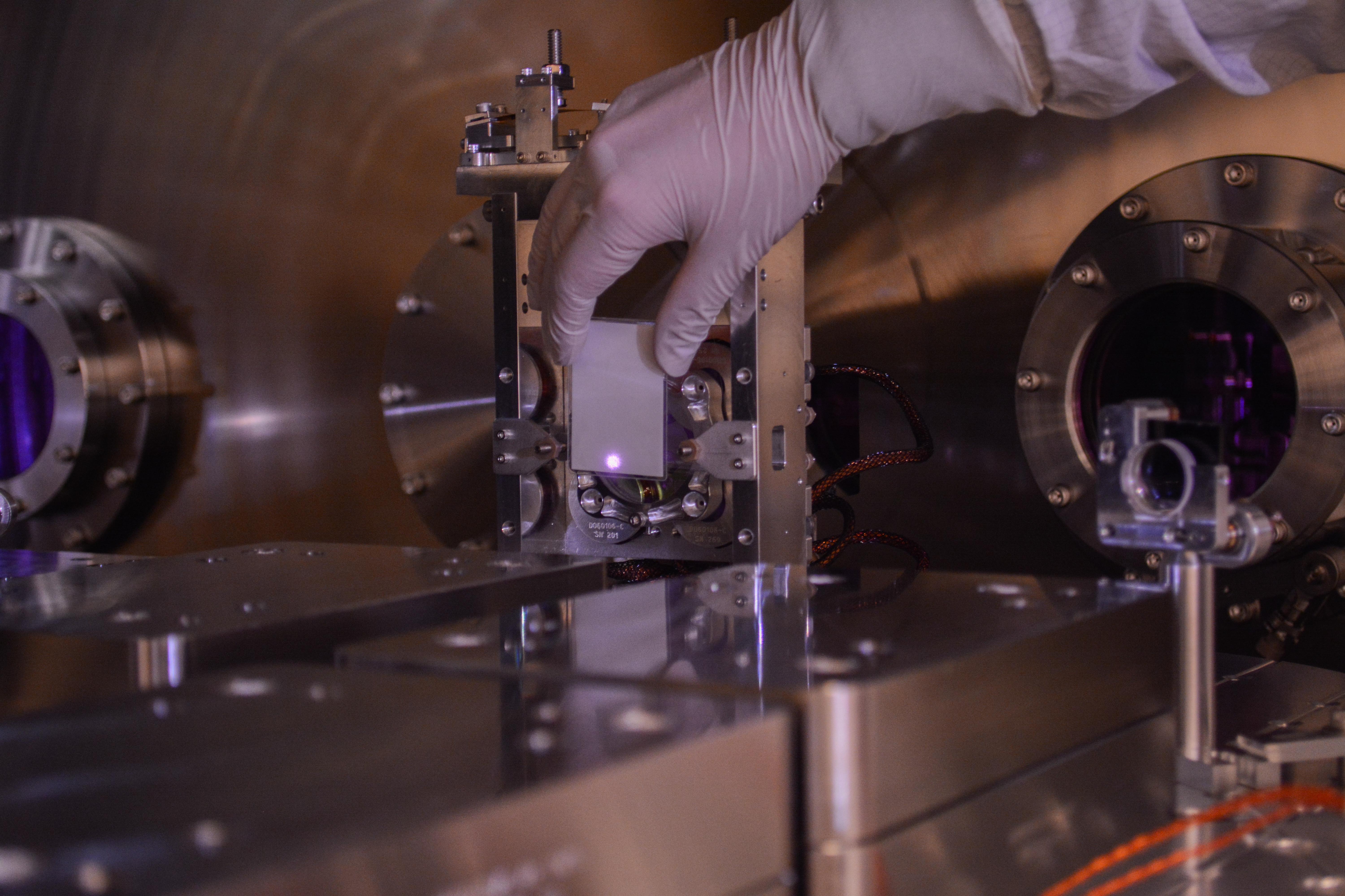
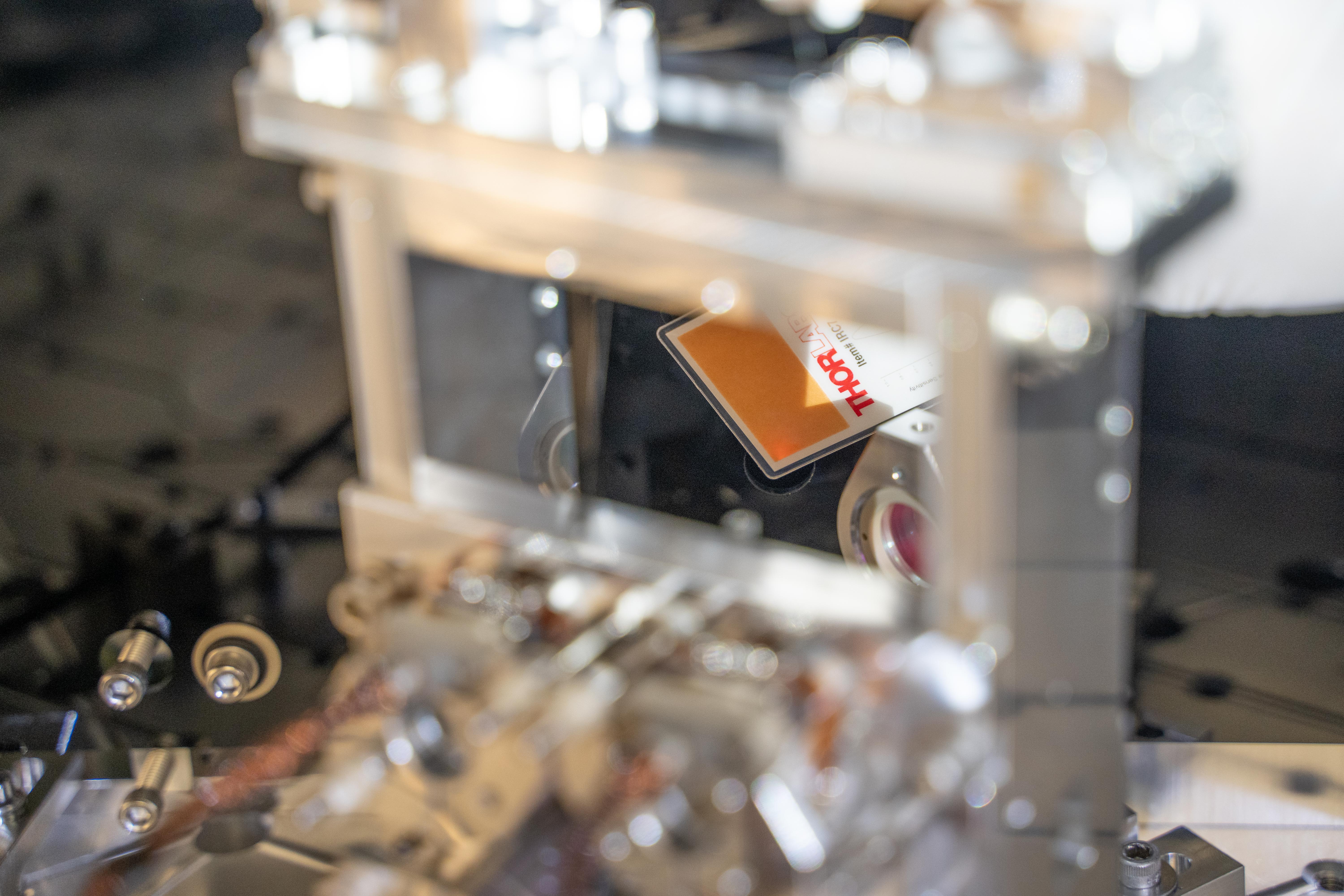
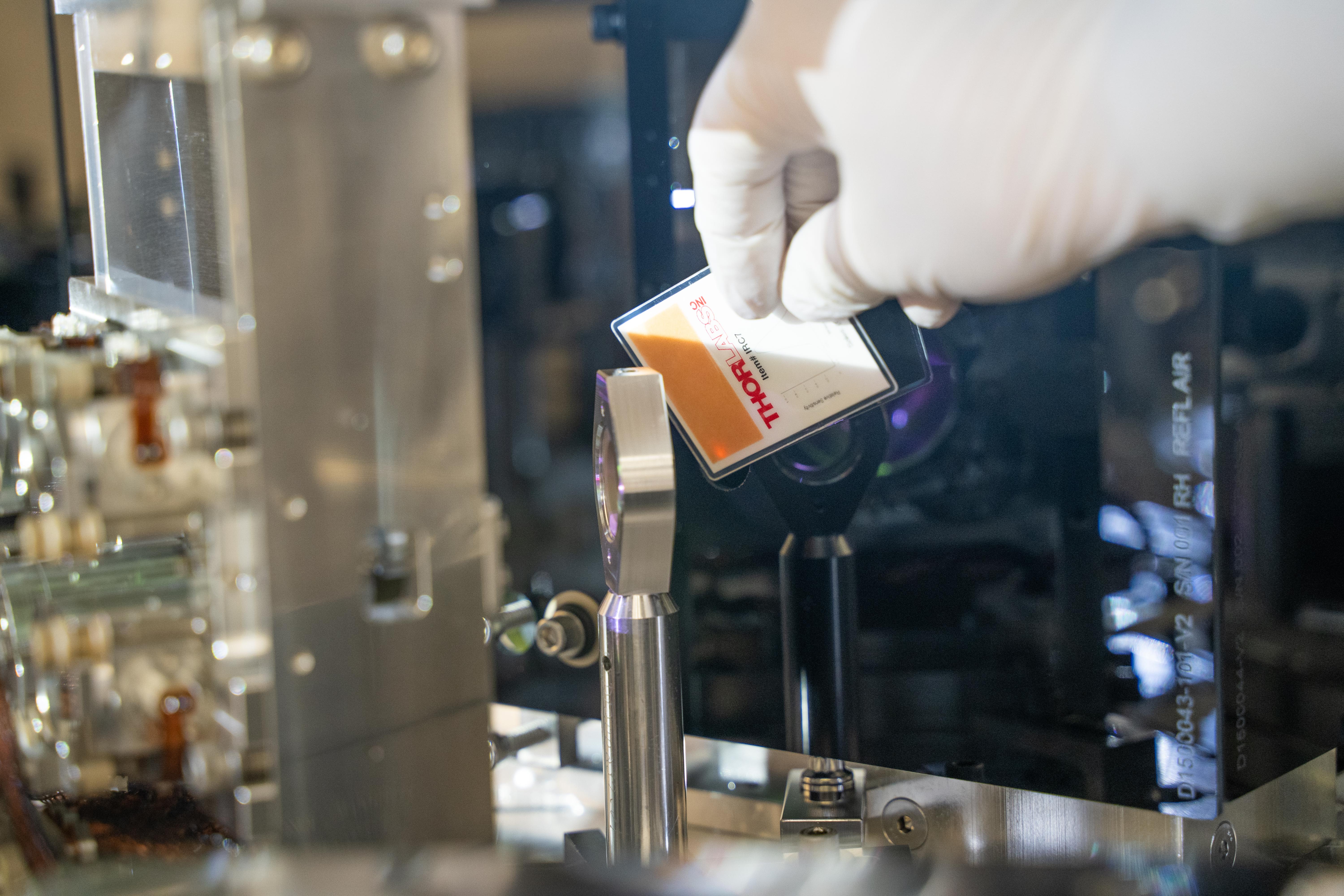
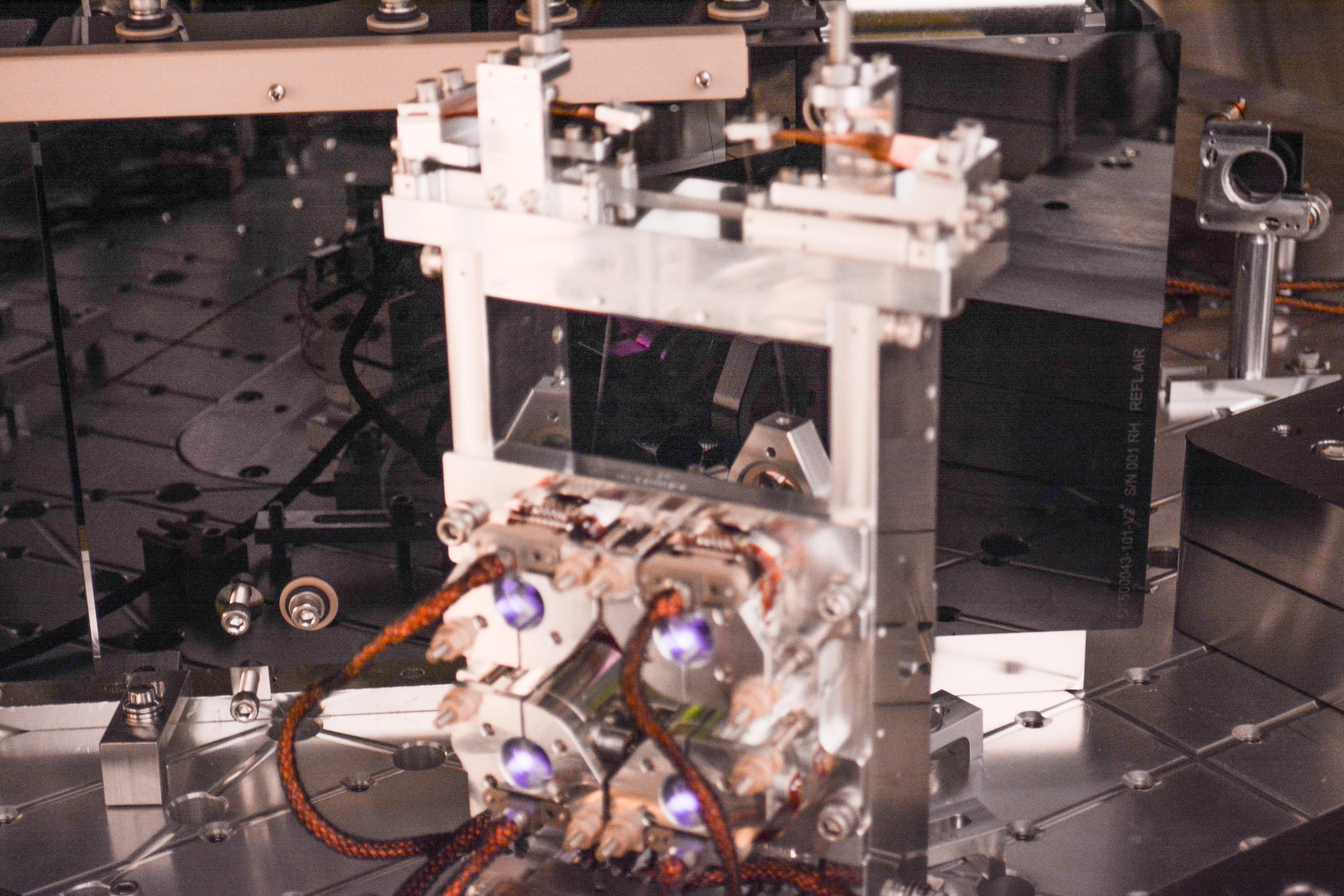
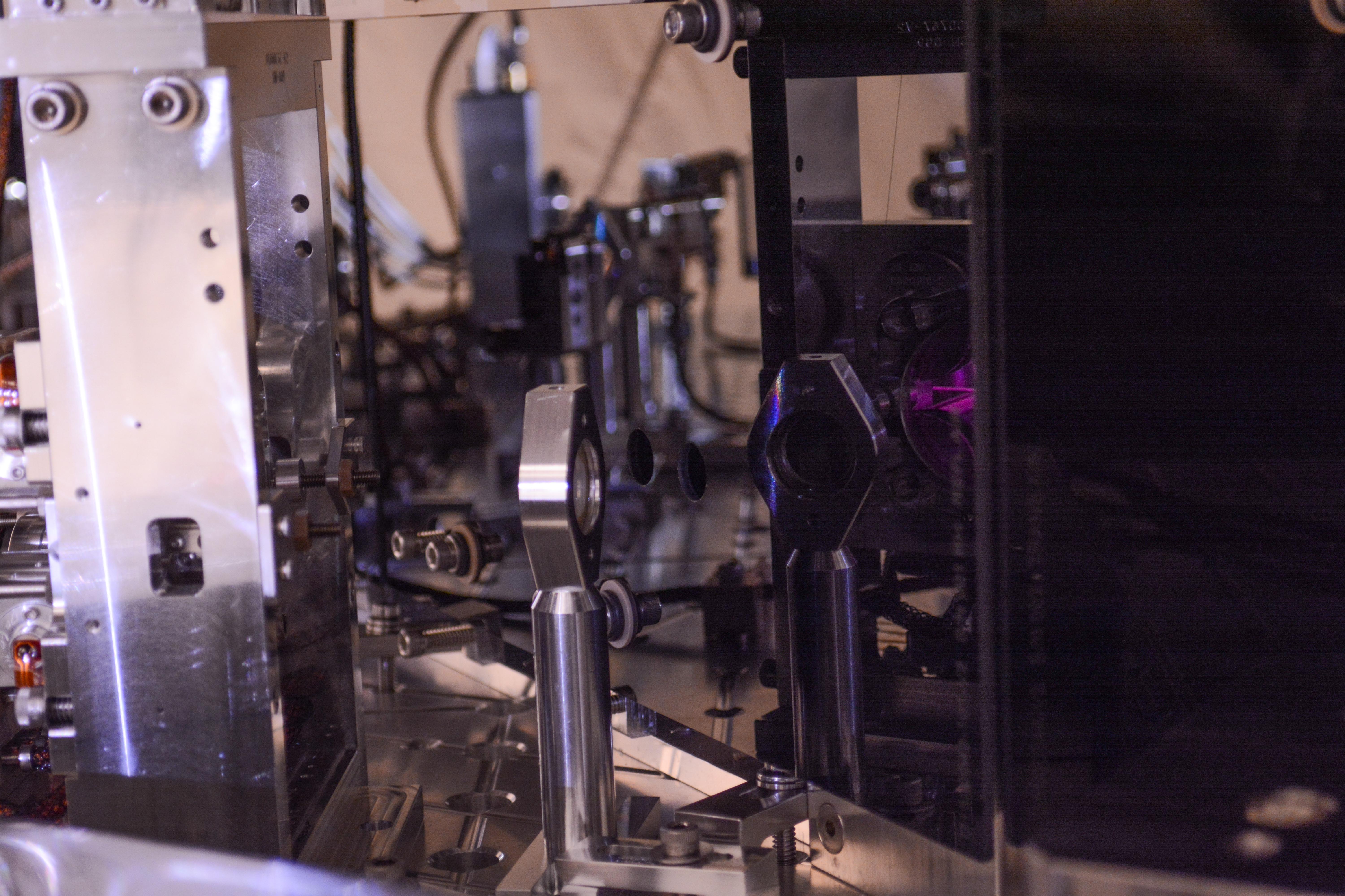
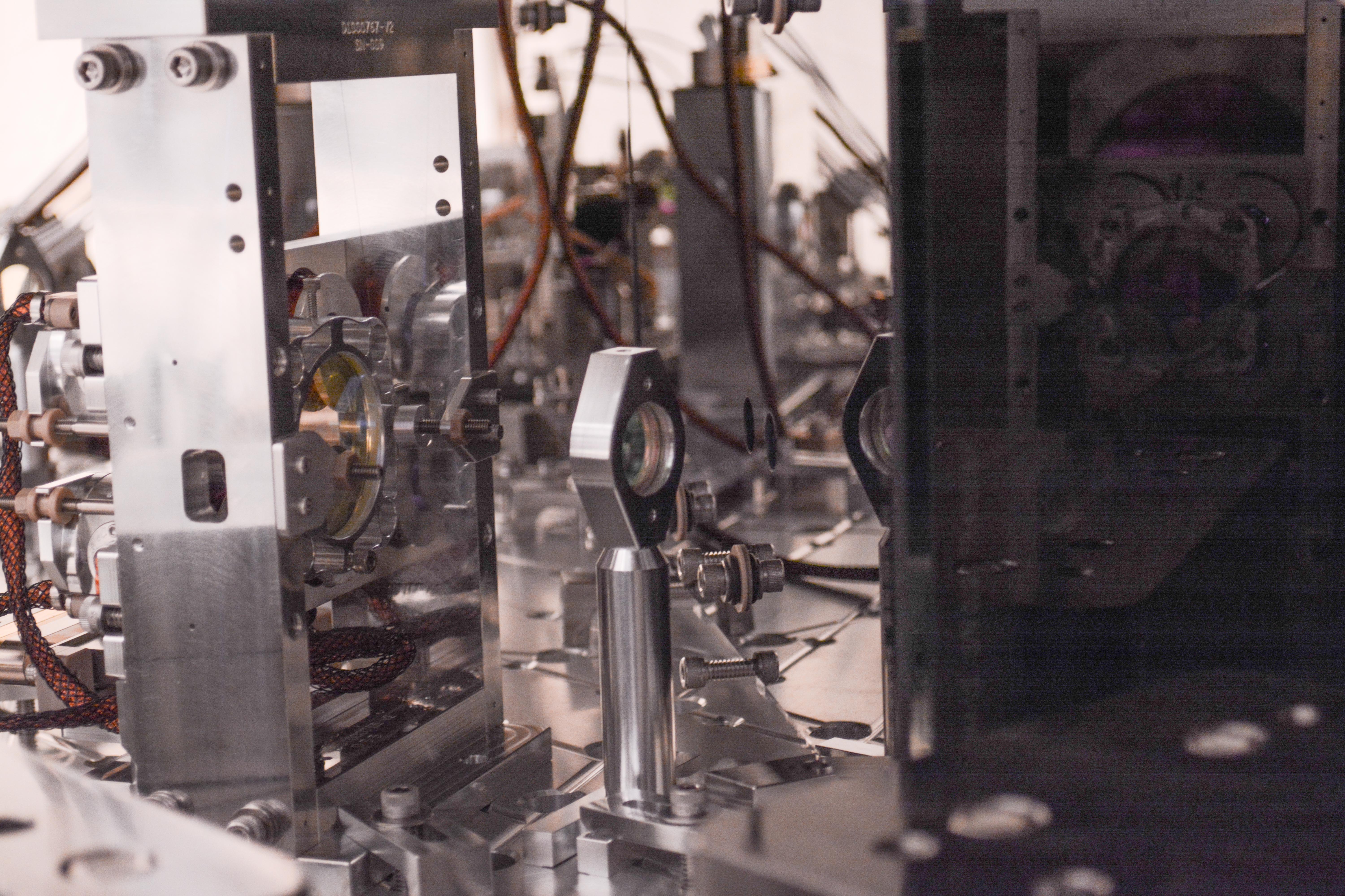
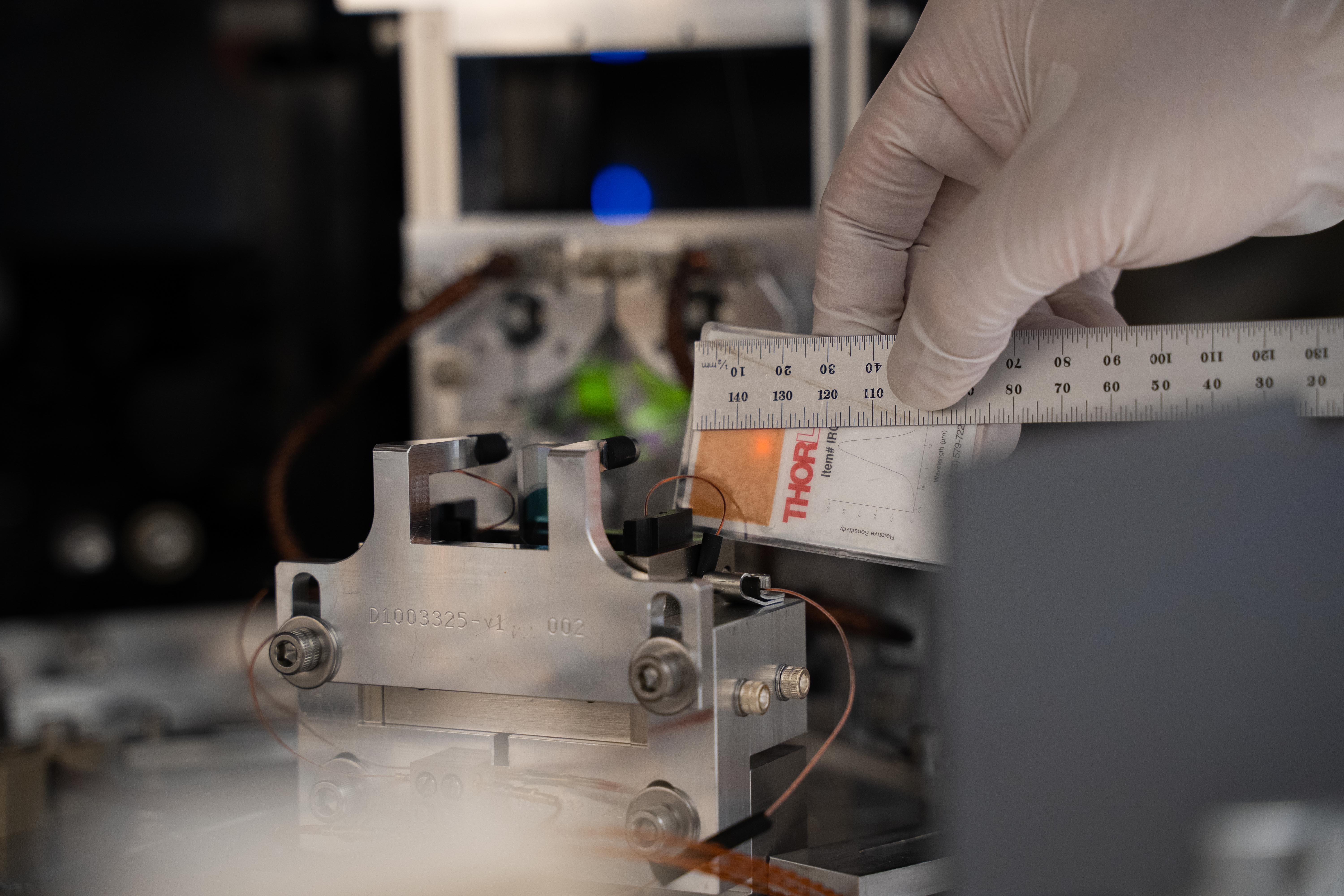


Before-swap pictures were posted in alog 52310.
Oct 11, 2019 Close-out sweep of HAM6 photos are here.
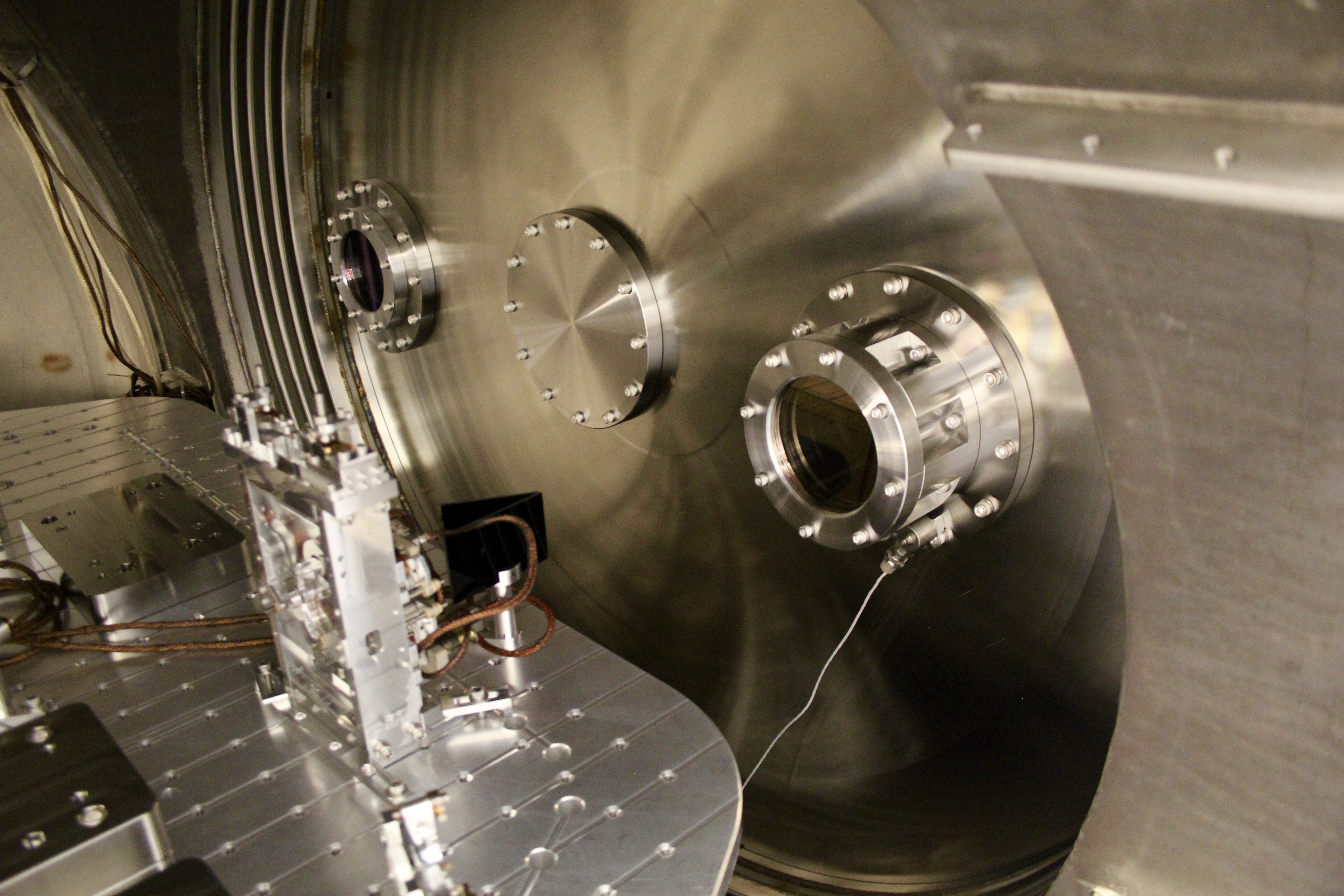
Since Resource Space appears to no longer be functionable/useable, here are some photos of the septum flanges/viewports.


Dan B., Cao, TJ
We swapped the TCSY flow meter because it was showing signs that it was going bad again (see alog51823). To do this, we followed the procedure that Betsy outlines in alog32776. We only encountered a few minor issues:
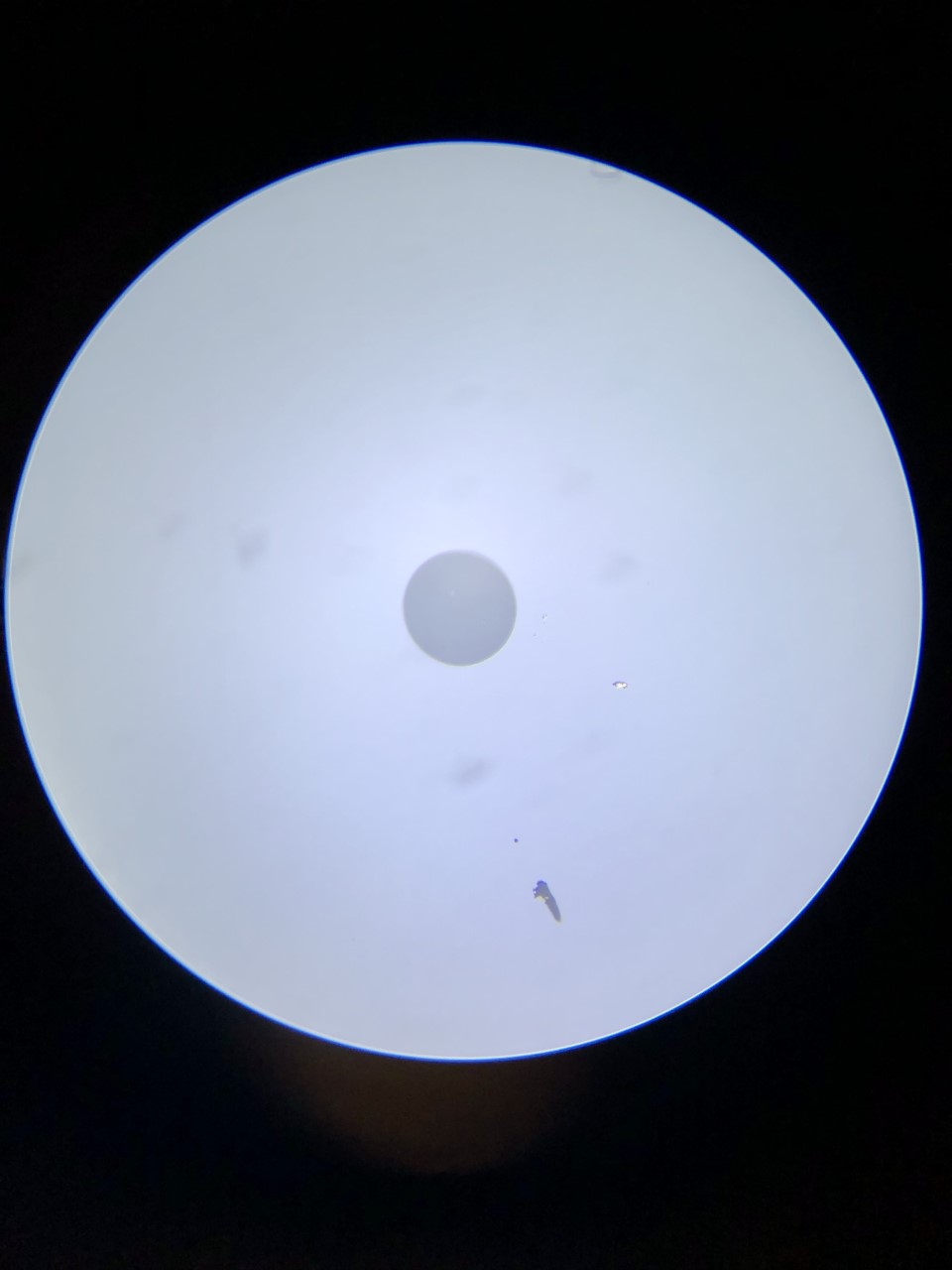
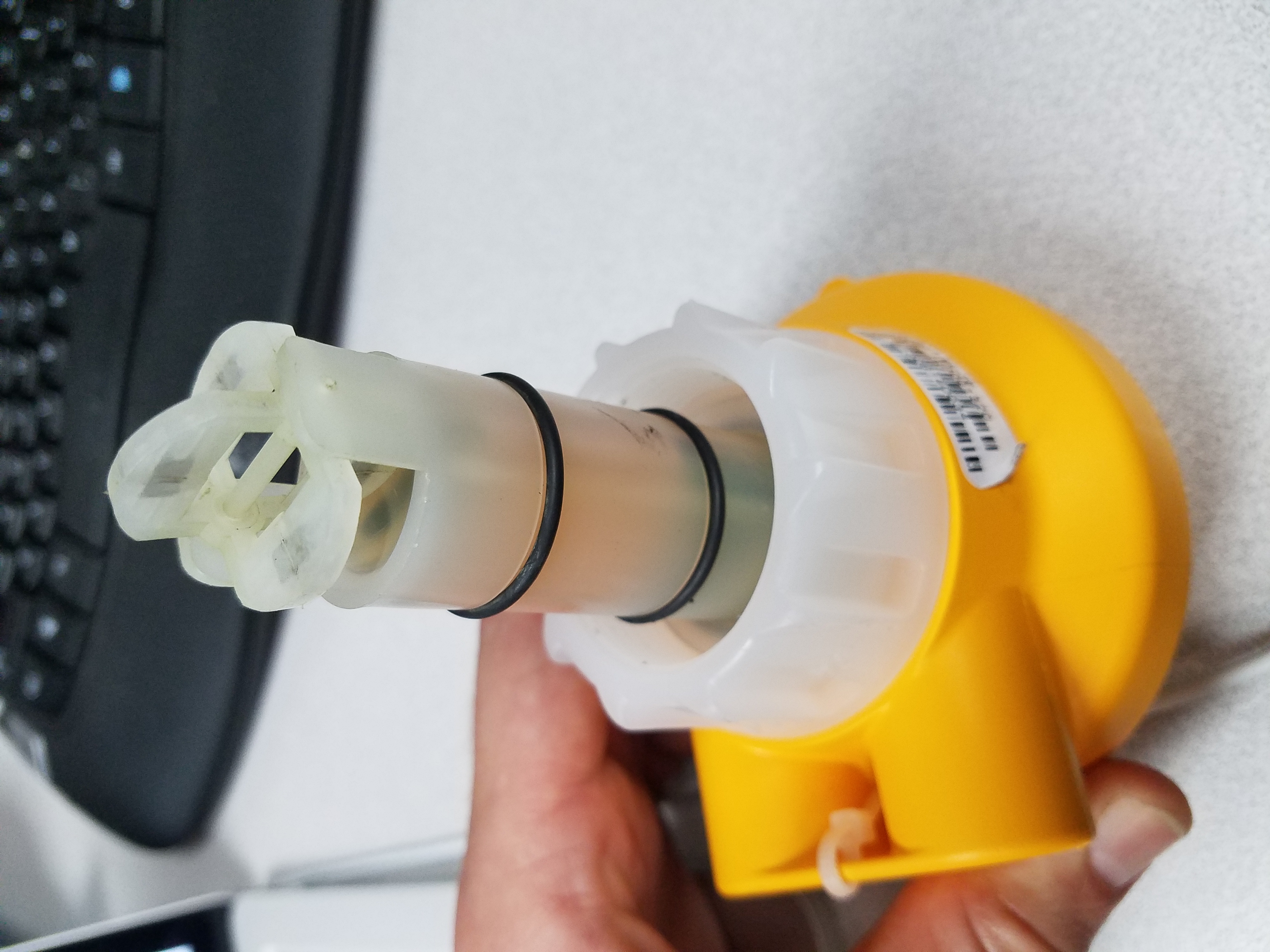
The flow meter that was taken out did not seem as dirty as the pictures of previously removed flow meters (see attachment). Hopefully this helps with some of the flow issues we have seen lately.
Summary of settings:
FLO Unit (Flow Unit) = G/m (default was L/m)
FActor (K-Factor) = 365.00 (default was 60)
AVErage (Average) = 10
SEnSit (Sensitivity) = 0
4 Set (4mA Set Point) = 0 G/m
20 Set (20mA Set Point = 10 G/m (default was 160)
ContrAST (Contrast) = 3
Serial numbers:
Old - 61308140034
New - 61606071363
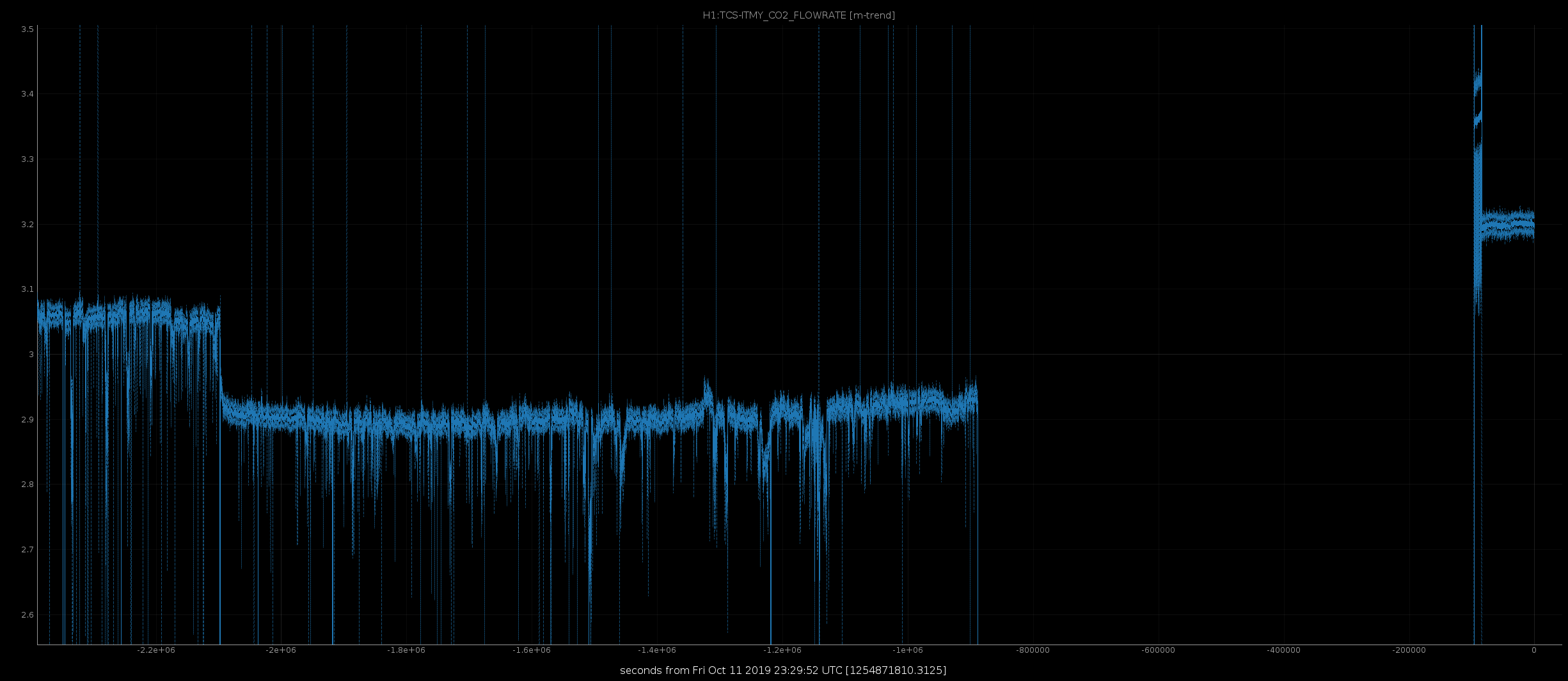
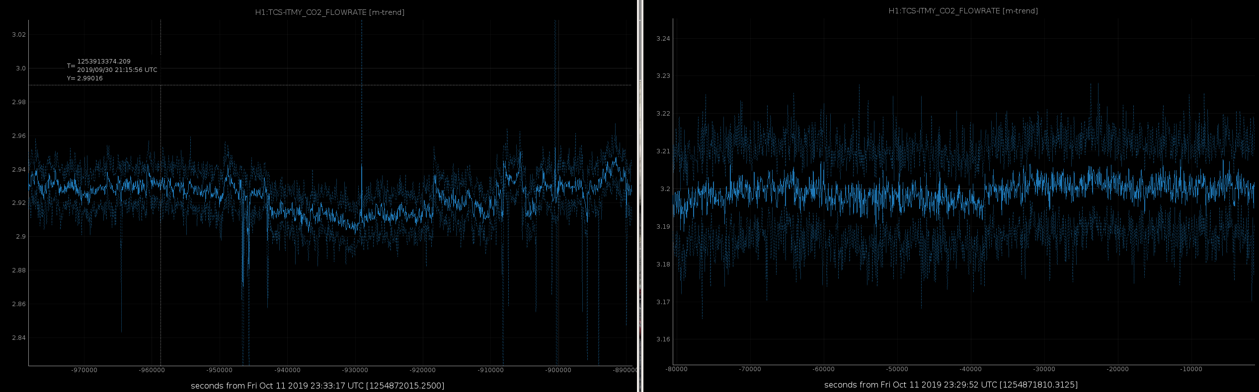
It's looking much better than before. See attached trend of ~80,000 seconds before the swap and after.
Today, Keita, Jenne, TJ, Nutsinee, Rahul, and I went in to inspect the beam paths that come from the AS viewport and to components towards the OMC. This is a pre-check of the beam location prior to the planned viewport swap early next week.
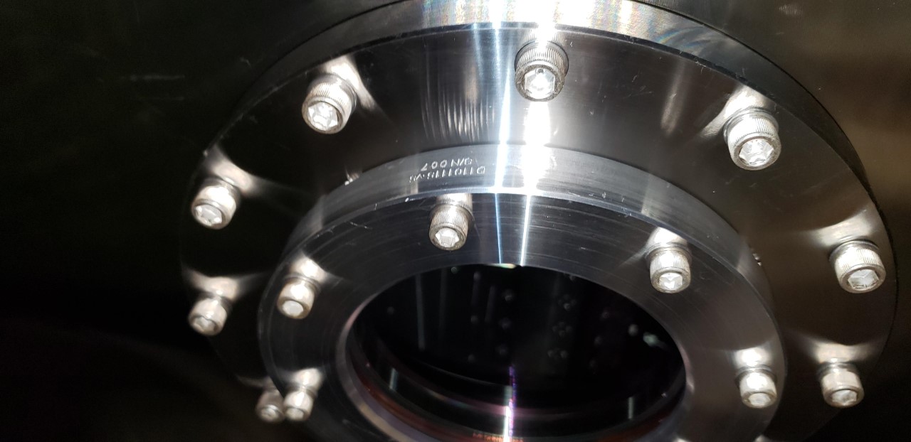
I verified that the viewport assembly does in-fact look to be the expected D1101095 s/n 003 assembly - I could see the D1101005 stamp (but no s/n) on the viewport glass itself, and the VP metal clamp part was labeled D1101115 s/n 007 - all consistent with the ICS assembly records which state the location of Septum Output. The D1101005 stamp on the optic was at the bottom of the barrel, which according to the drawing means the arror (thick part) is on the 3 o'clock position, as previous installation alogs report. Good.
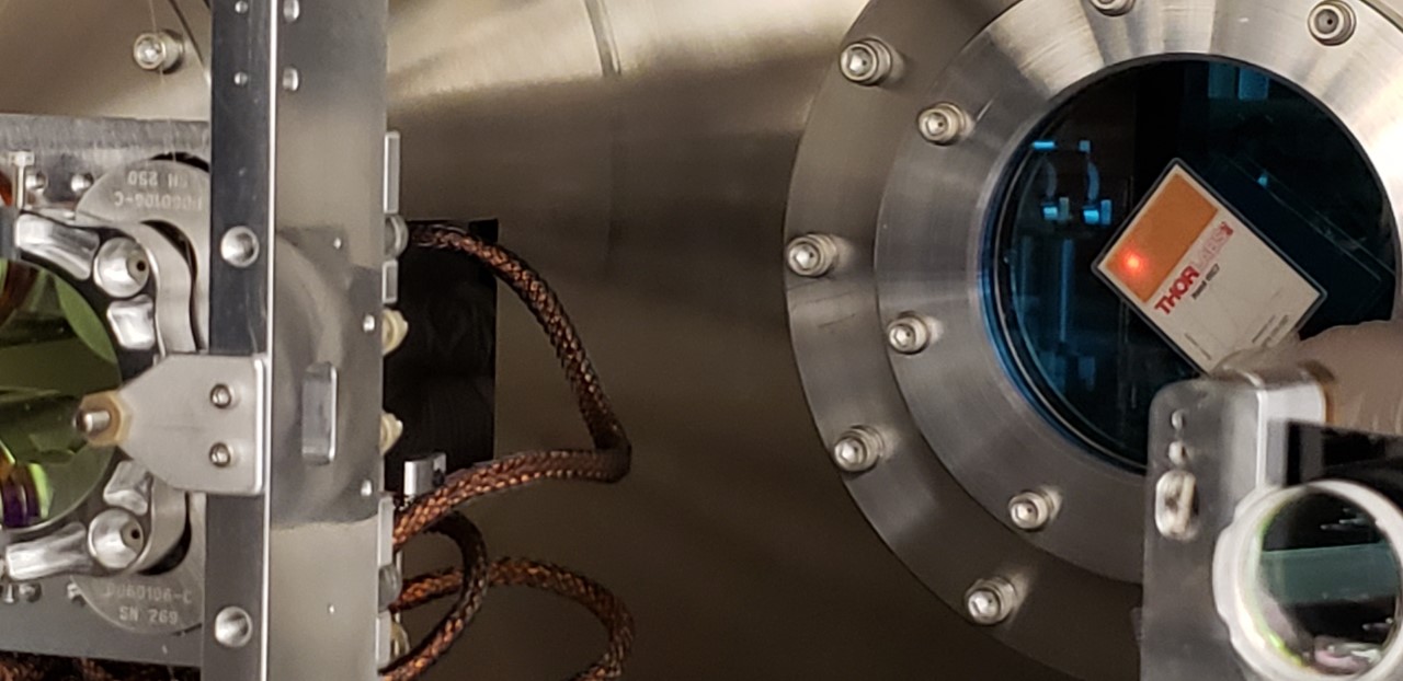
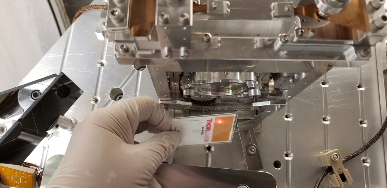
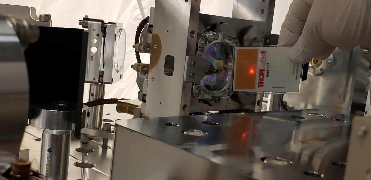
The location of roughly where the beam comes through the VP is shown in the attached picture. Because we did not want to get the card too near the viewport surface, it the view is a little bit subject - I tried to get the camera view roughly at the beam height.
Jenne then steered the SM to center on the AS_C QPD. Things looked pretty aligned along the path.
Pictures 3,4,5 are of beam location pitch and yaw views in front of OM1, and then location of beam in High Powered beam dump aperture.
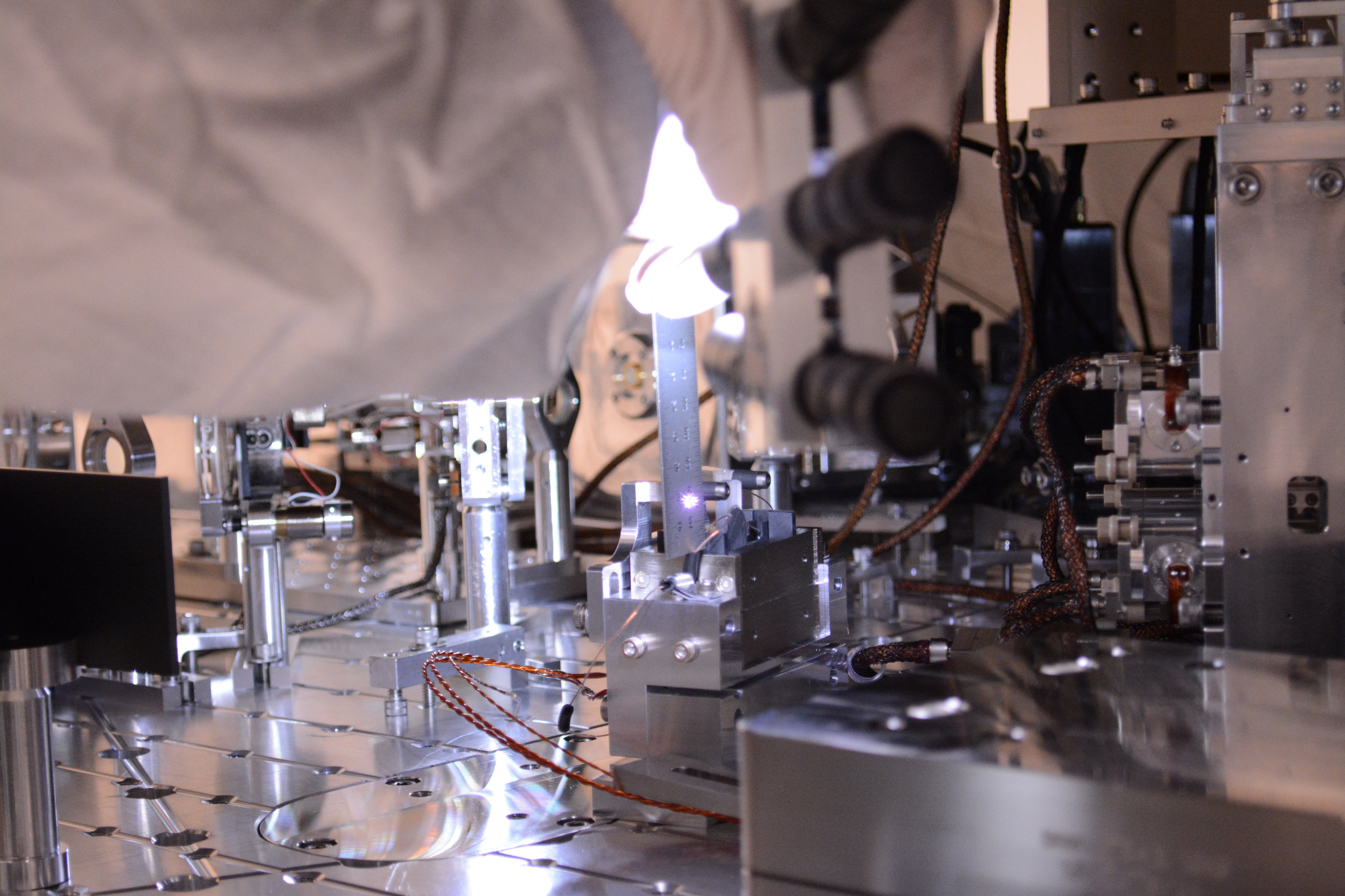
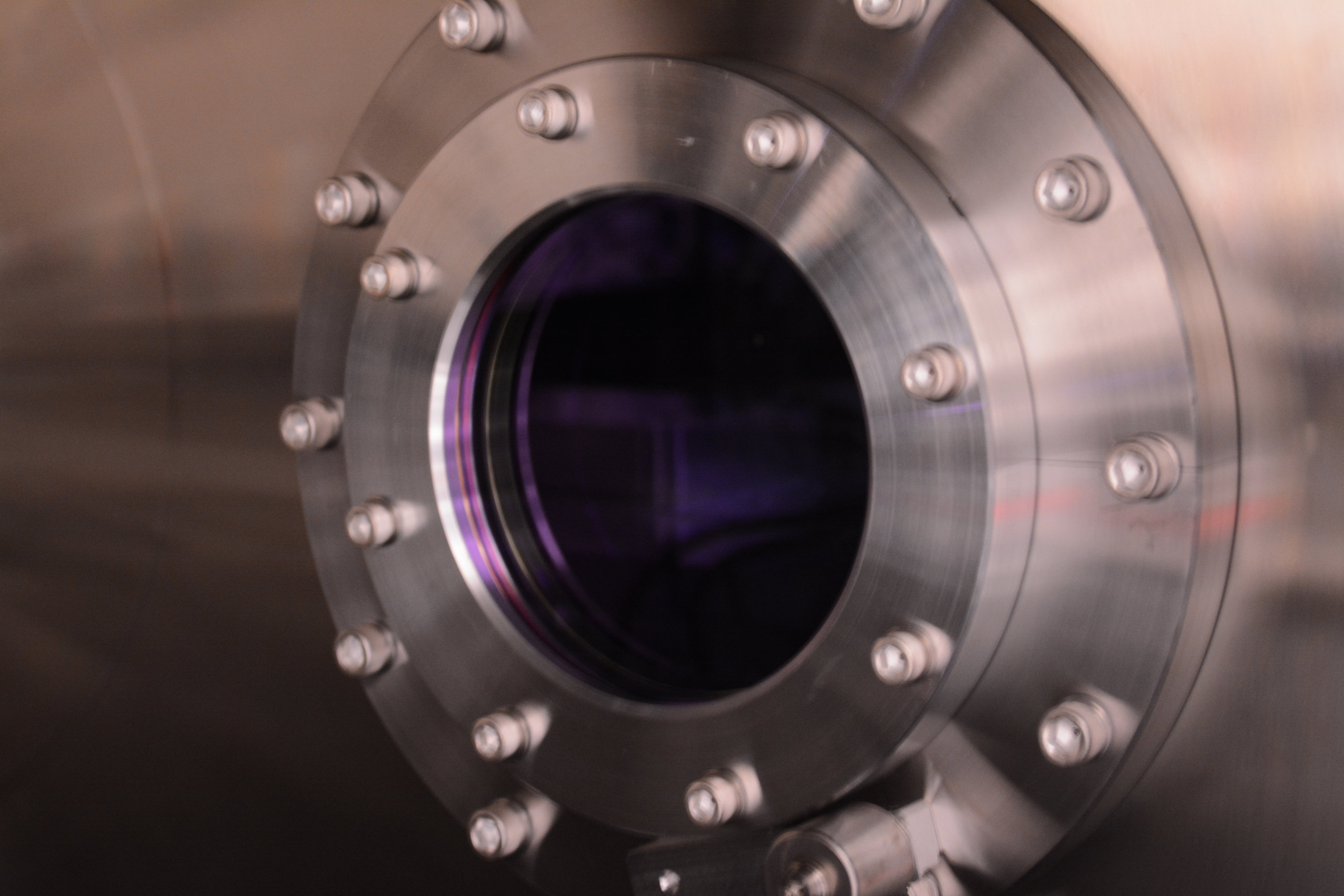
Attached some of the not-so-scientifically-useful photos as requested by Betsy. If anyone needs high resolution of any of these photos ping me.
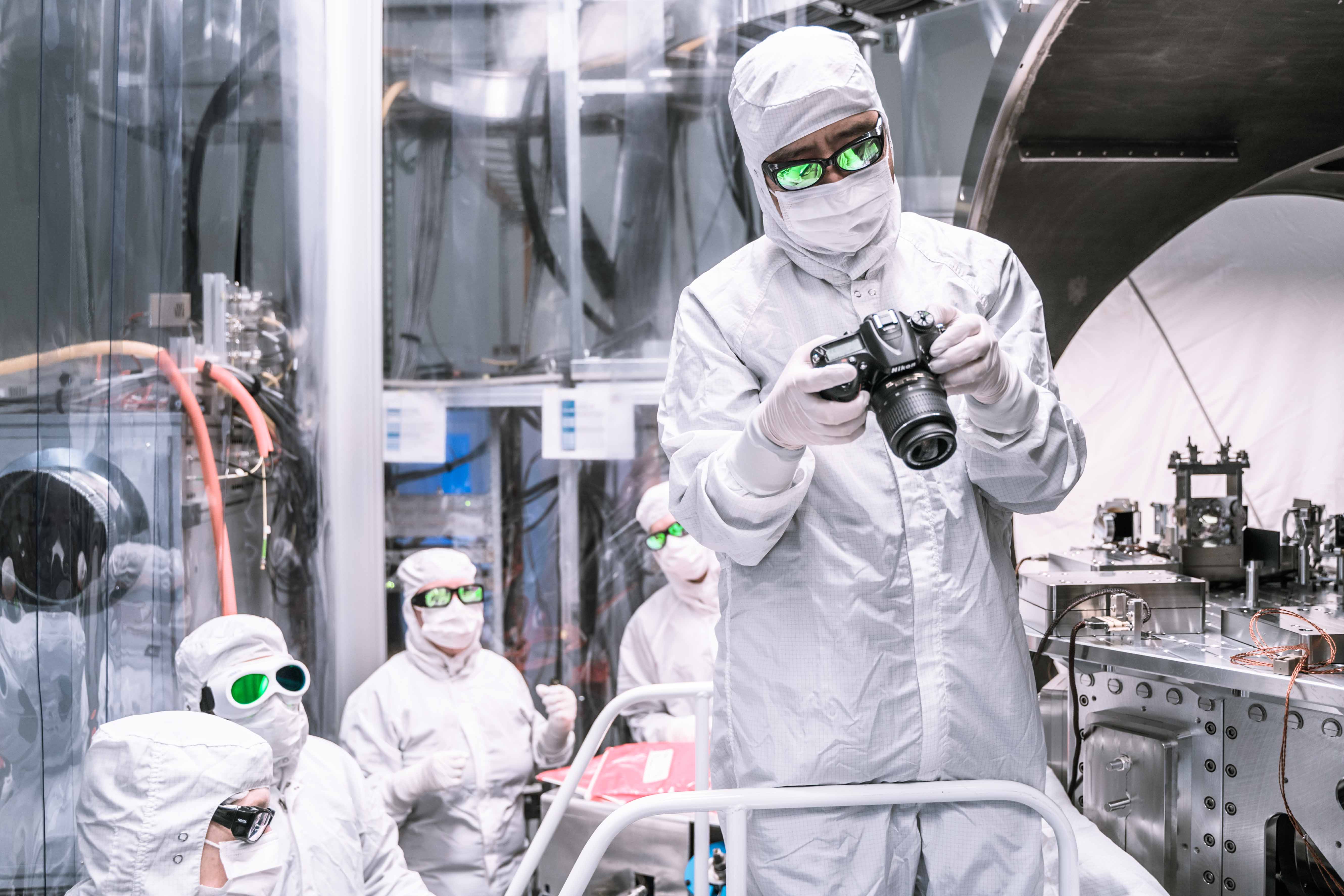
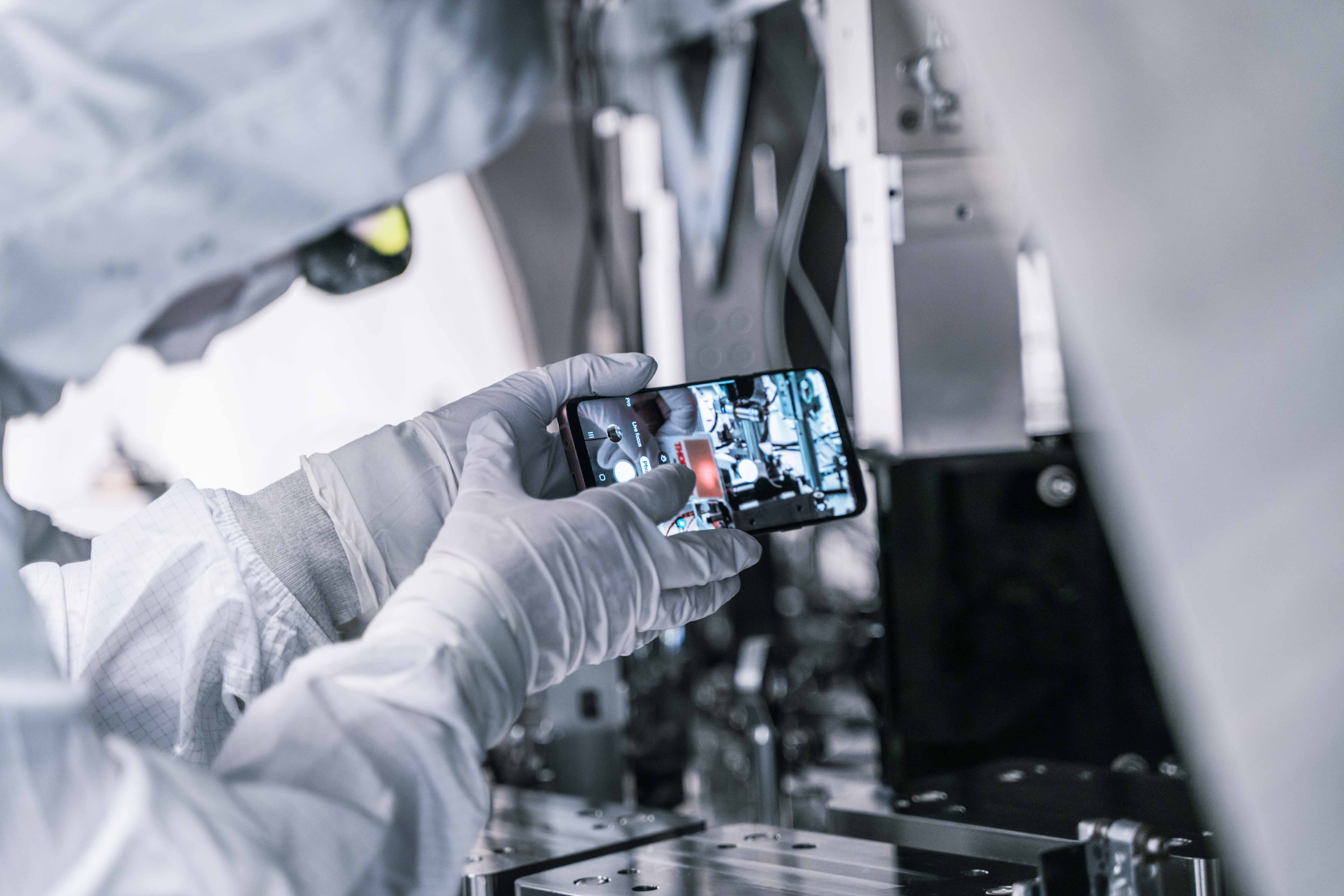
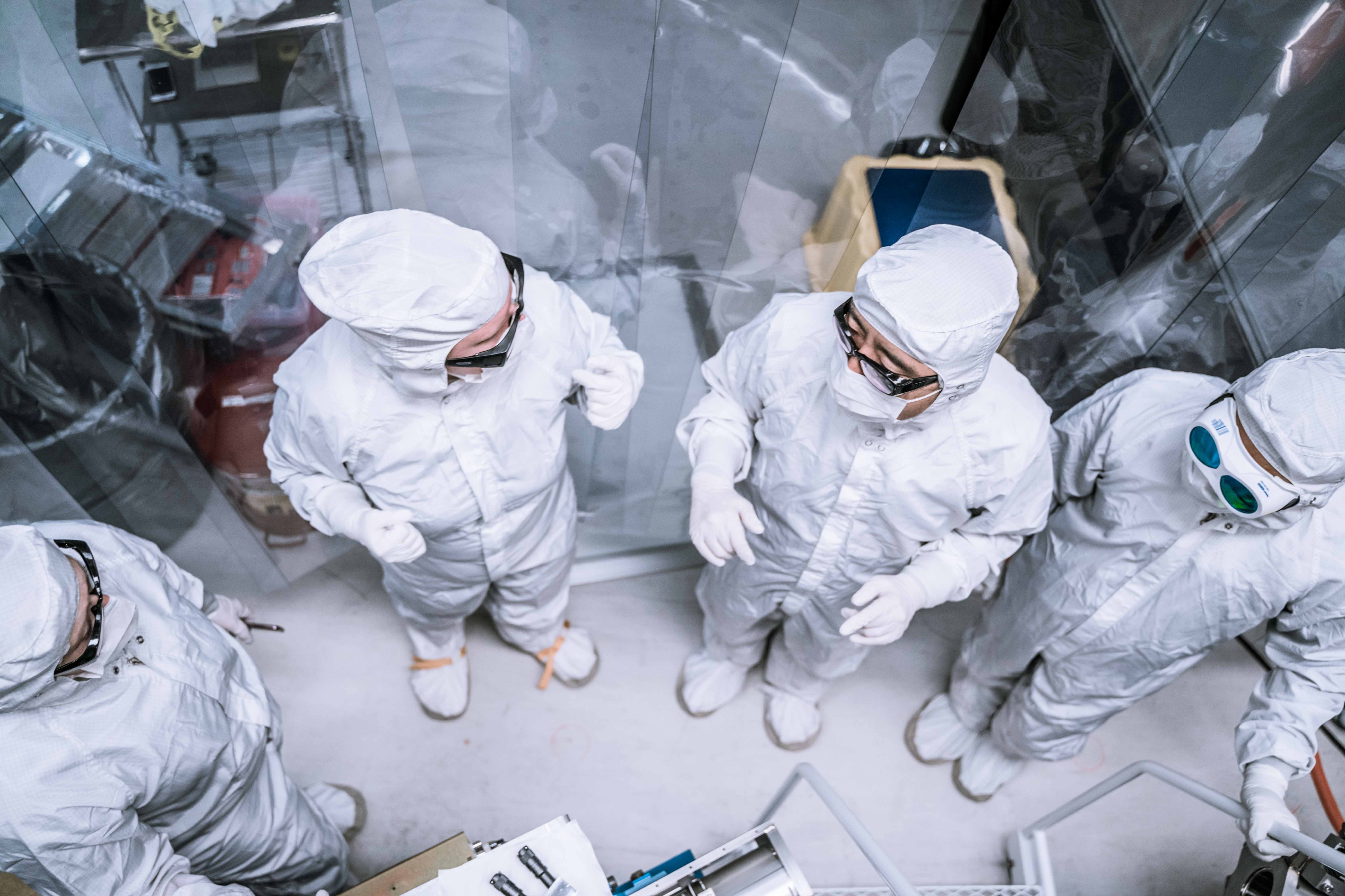
Additional photos.
1st one is the beam going from the septum to OM1, getting close to the fast shutter (but it's not really that close in reality).
2nd one is the septum viewport itself, the thicker side mark is in +X direction. We couldn't see any IR scatter with this exposure setting (this is an IR-sensitive camera). IMC was locked at 5W, so the power hitting this window should have been roughly 10*3%*25%*32%=24mW.
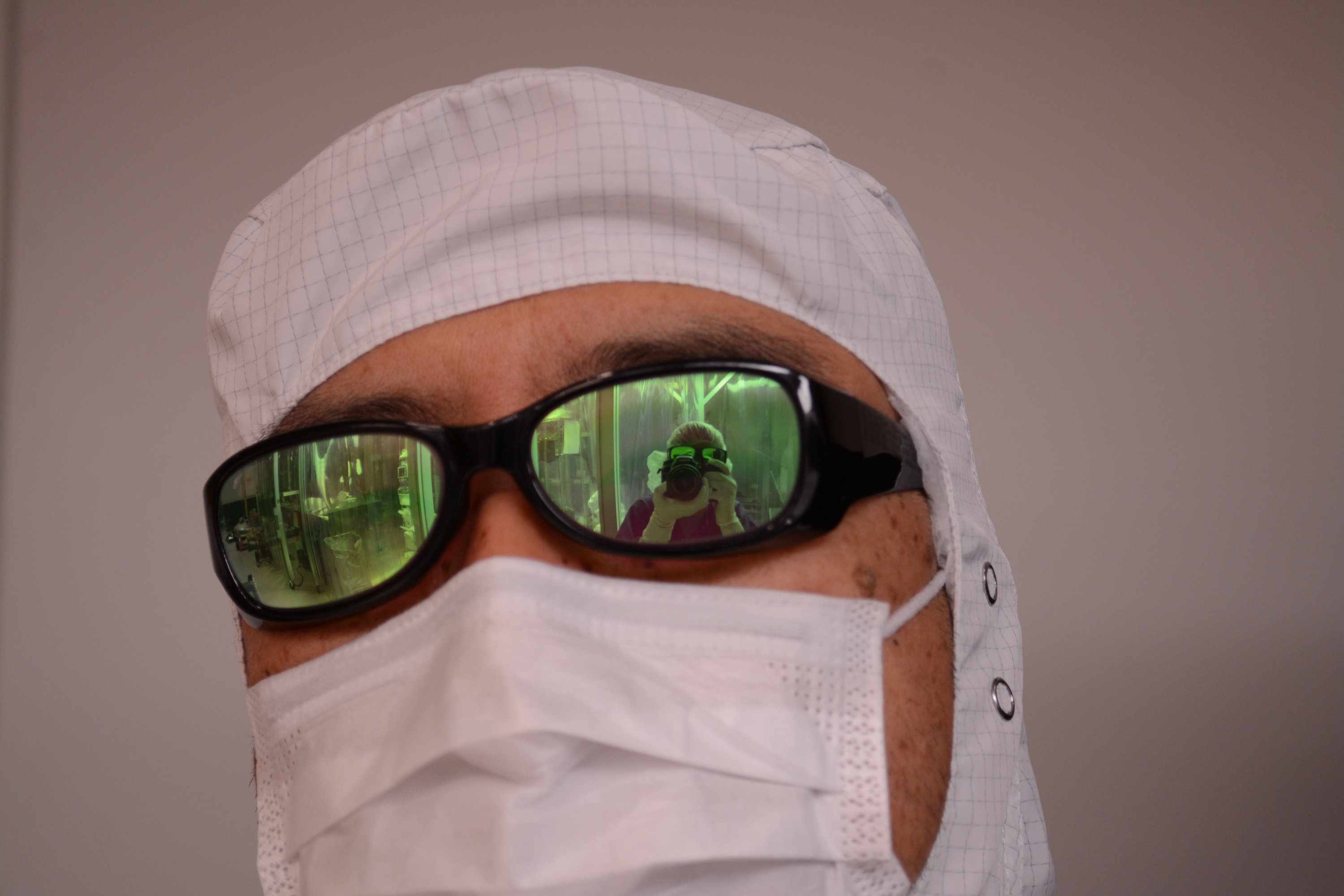
The last one is the photographer taking selfie using the reflection on my safety glasses.
These are all before the viewport swap, obviously. After-the-swap photos are available in another alog (52409).

Per LIGO-M1300464, the procedure is to disable ring heaters during pressure transitions because it is unclear how heated metal will react to pressure changes.