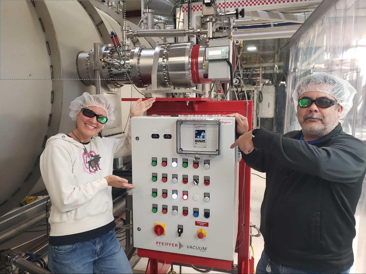
Valved in the new ATH2303 turbo at XBM to lower pressure from mid -4 Torr range to 2e-6 Torr, but don't want to leave it unattended until is has chilled water routed through electronics. It is valved back out and spun down. Electronics temp. rose to 49C.
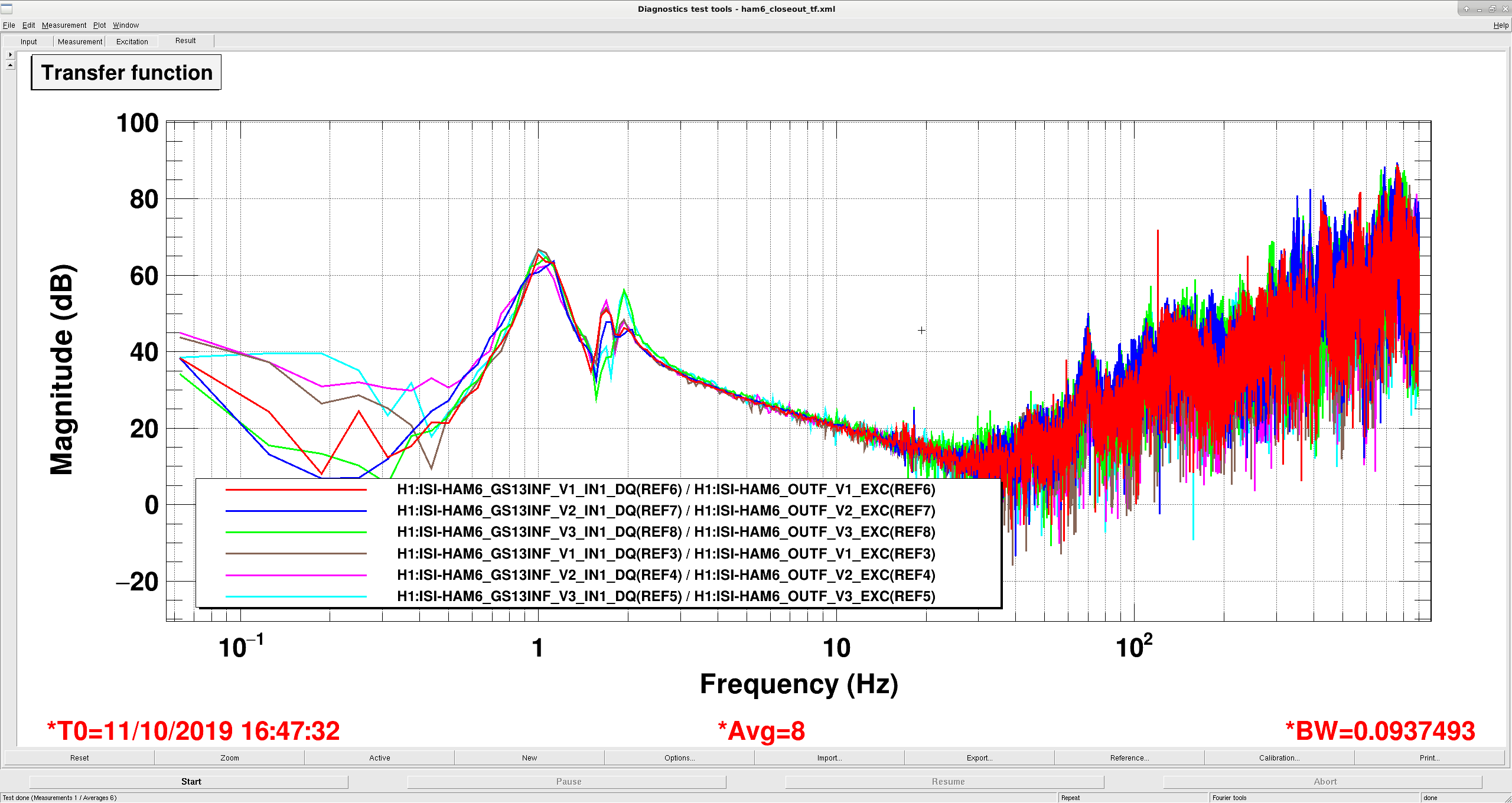
I unlocked the ISI this morning, after fixing some poorly routed cables on the east side of the ISI. ISI tfs look okay, all of the current tfs are the red, blue and green traces on the attached plots, and are refs 6-11. Refs 0-5 are from the previous closeout. There is a small wow at 3.5hz on the H3 tf (ref 11), but I don't think it's a problem. Maybe coming from one of the suspensions? JeffK told me all sus were damped, but maybe not?
for PCal work
18:17 EY is now LASER SAFE
TITLE: 10/11 Day Shift: 15:00-23:00 UTC (08:00-16:00 PST), all times posted in UTC
STATE of H1: Planned Engineering
OUTGOING OPERATOR: Patrick
CURRENT ENVIRONMENT:
SEI_CONF state: SC_OFF_NOBRSXY
Wind: 7mph Gusts, 6mph 5min avg
Primary useism: 0.12 μm/s
Secondary useism: 0.17 μm/s
QUICK SUMMARY:
Transitioned the LVEA to Laser safe for the door installation team.
[Keita, Nutsinee, Sheila, Jenne]
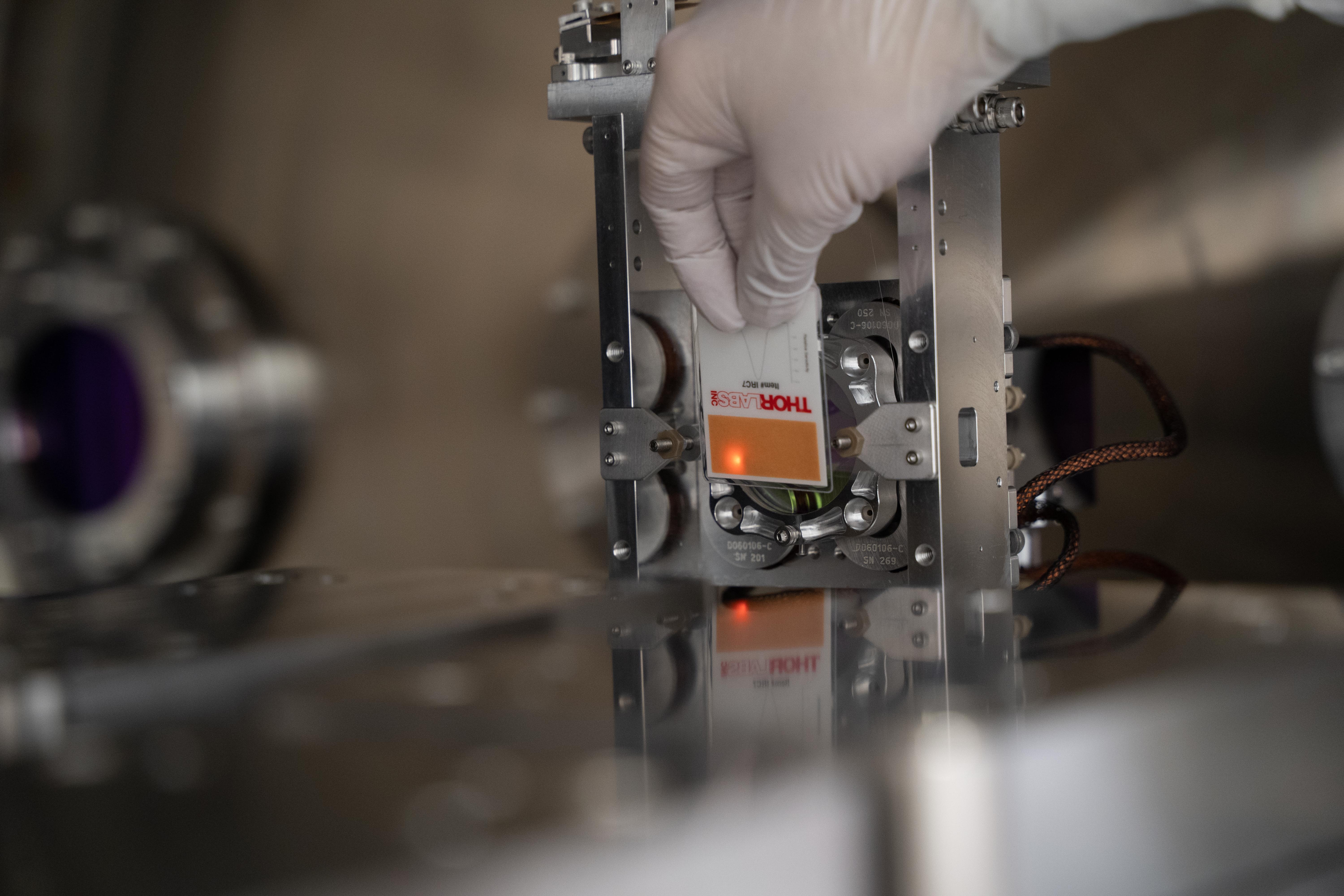
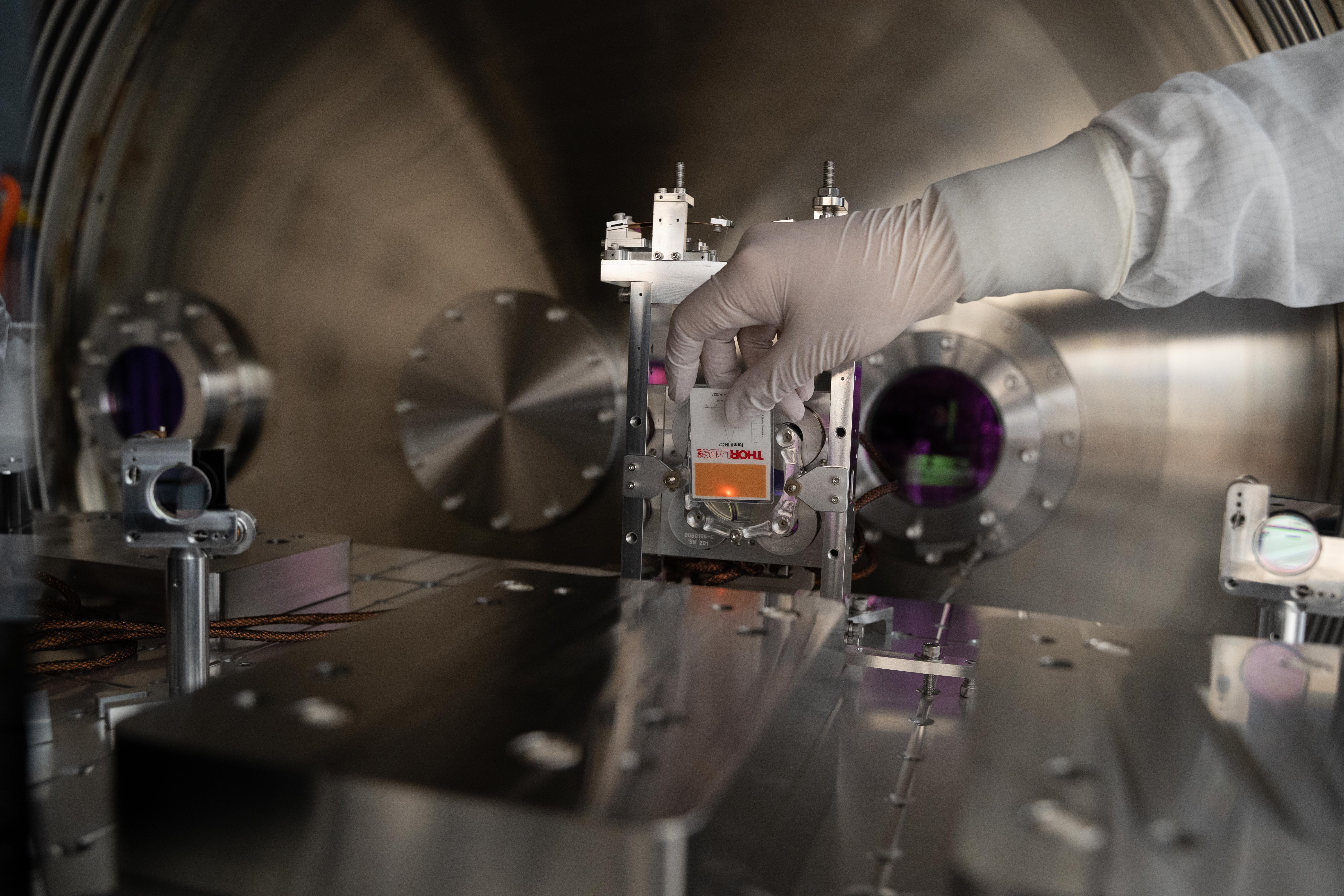
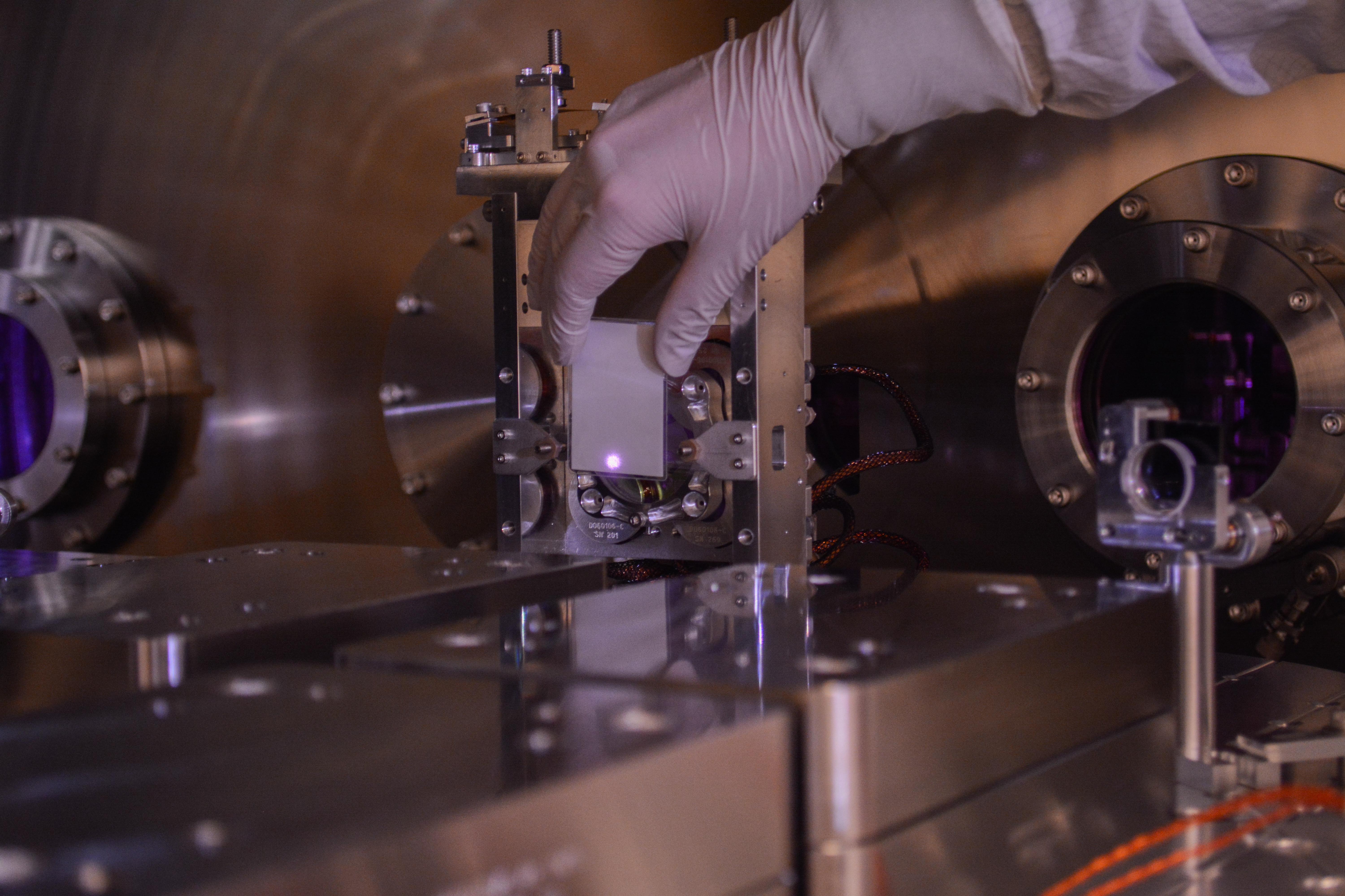
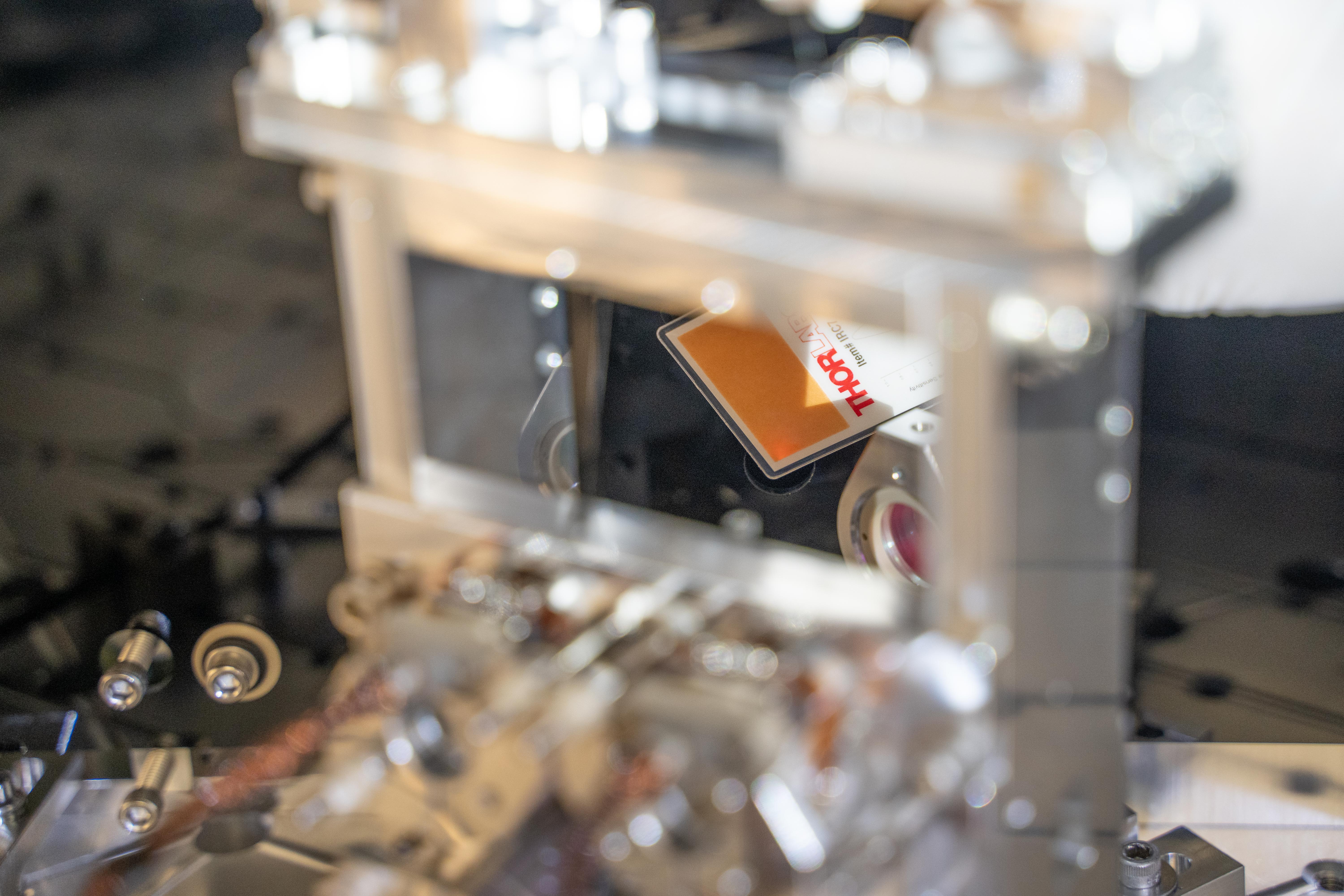
We went in to HAM6 today, and believe that we have finished all ISC/SQZ related tasks, and are ready to begin closeout procedures tomorrow. (Betsy, who has the final say, will write an alog or talk to the relevant folks for the actual final start of closeout.)
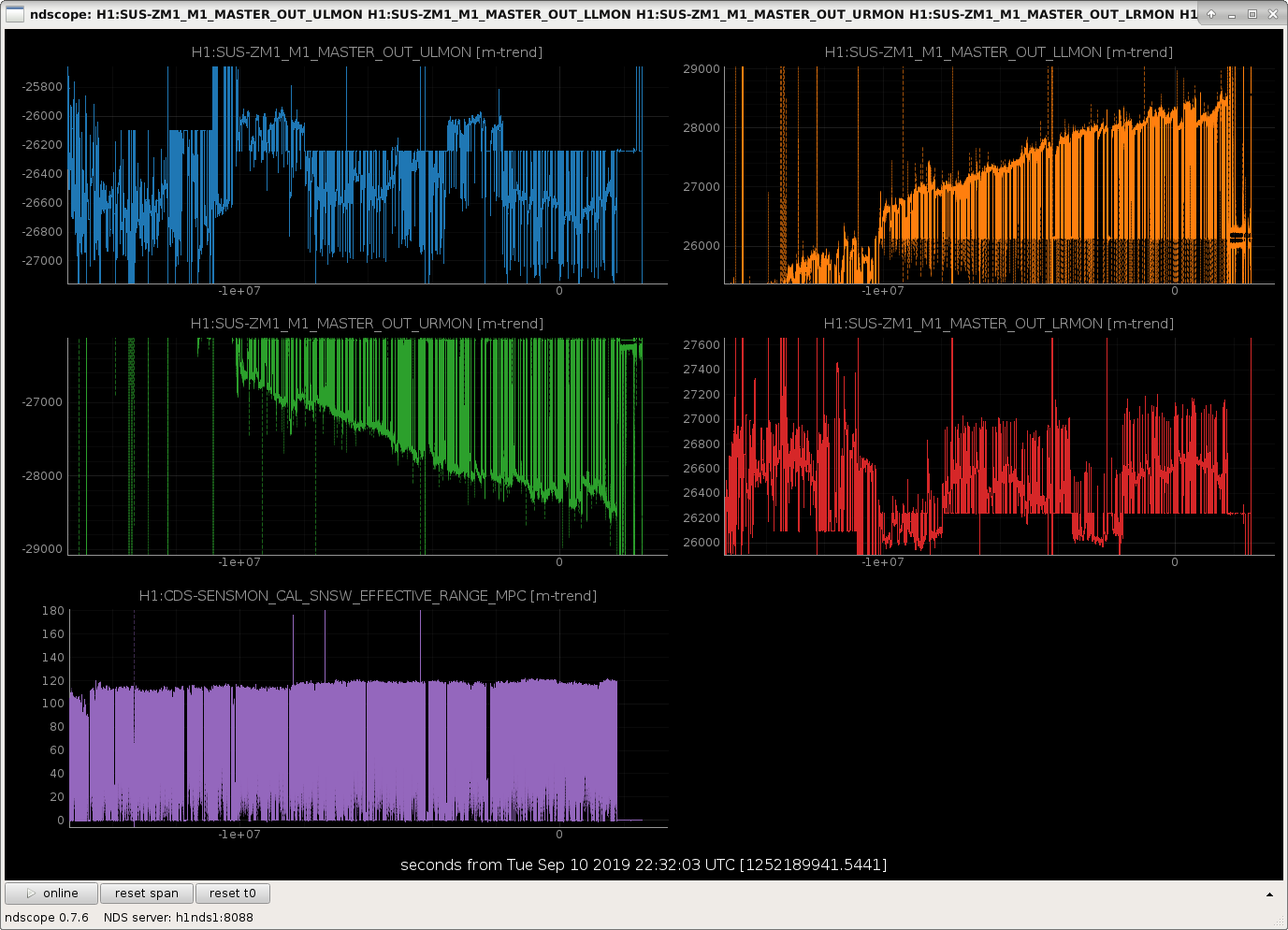
After Richard opened the PSL shutter and Ed locked the IMC, we pretty easily were able to get beam onto AS_C. To check our alignment, Sheila aligned the Michelson, then made sure we were still centered on AS_C. Since we don't have arms, we just assumed that the input beam is pretty close to its usual, and only adjusted ITMs and BS for MICH. Around this time, Keita noticed that there was a bit of a 'tail' on the beam as seen on an IR card. Sheila walked SR2 and SR3 until the tail was gone, but we were still centered on AS_C. After this we aligned SRY (restored SRM, misaligned ITMX) to get good fringes, so that we could trust the SRM position for squeezer-related work. We also took the IMC offline (which misaligns MC2) to remove the main IFO beam, injected the SQZ beam, ran the squeezer's ASC loops, and noted that the ZM1 actuators were very close to the edge of their ranges (as Sheila made a quick note about in alog 52405). We deferred action on this until after the main IFO path checks were complete.
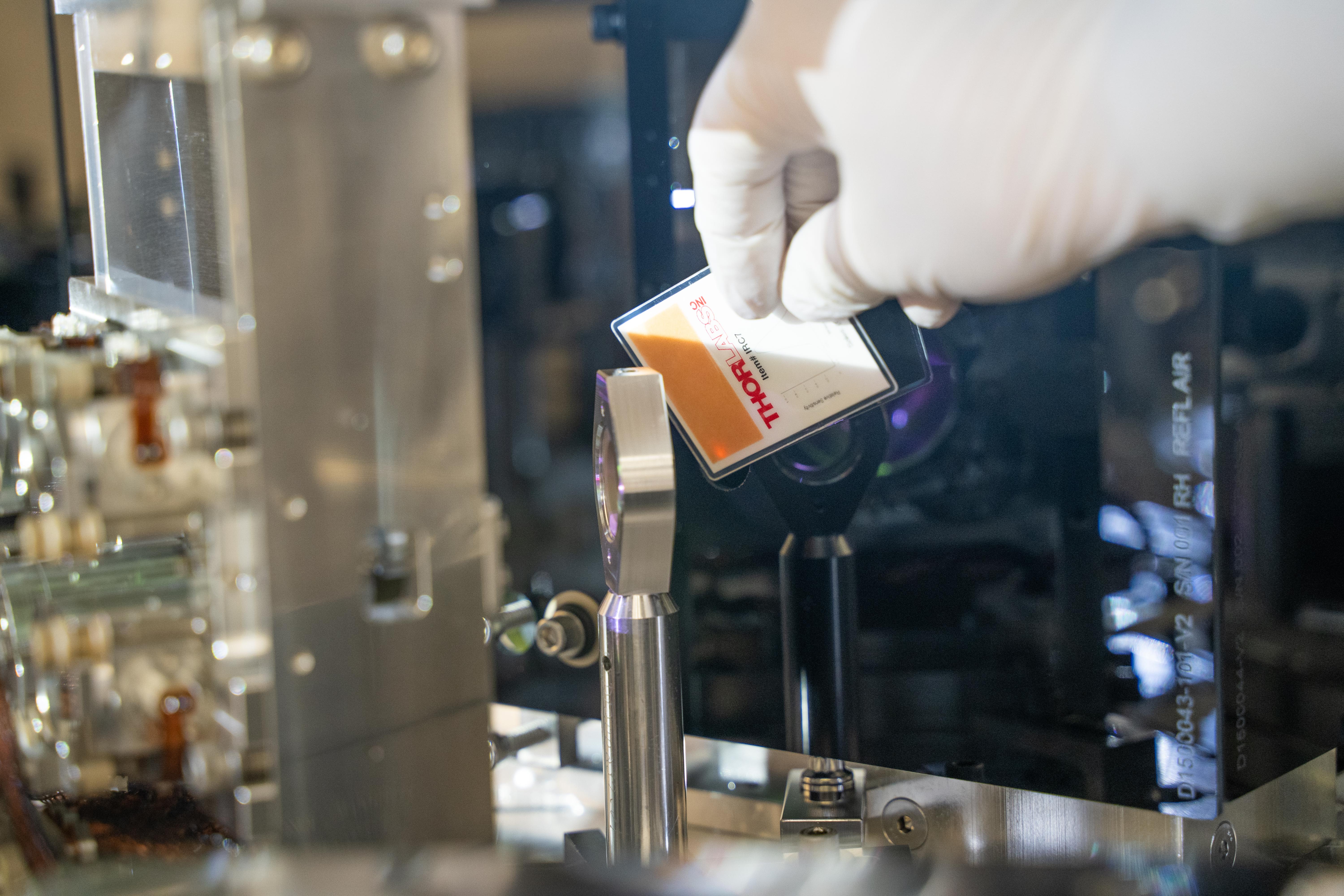
Once we were happy with all of our alignments we brought the main IFO beam back and Nutsinee took photos of the beam in several different places, including the septum window, the position on OM1, the position relative to the fast shutter's wire, the position on OM2, the position going into and returning from the OMC shroud, and some photos to ensure that we don't see any obvious scattered light at the shroud apertures.
Having completed this, and deciding that it was still quite early in the day, we began work on relieving the ZM1 actuator. Sheila noted that the pico that is on/near the OFI is closer in Gouy phase to ZM2 than ZM1, so would not be a satisfactory way of relieving ZM1. Sheila and Keita went in and adjusted the last steering mirror on the VOPO platform that sends the beam to ZM1 about 1/4 of a turn in yaw, clockwise if you are standing at the endcap. After I damped the VOPO we re-ran the squeezer alignment loops, and found that instead of having outputs of nearly 29k the ZM1 outputs were at most about 7k. Excellent! We note that the ZM2 outputs are around 22k, but this is the same that they were during O3a, it hasn't drifted, and if we need to we can relieve ZM2 using the pico, so we are leaving things as-is.
With these 2 sets of checks and work, I believe that we are done with ISC/SQZ work in HAM6. Nutsinee will comment with her photos.
Nice work team!! We'll mobilize to do the chamber unlocking and closeout tomorrow!
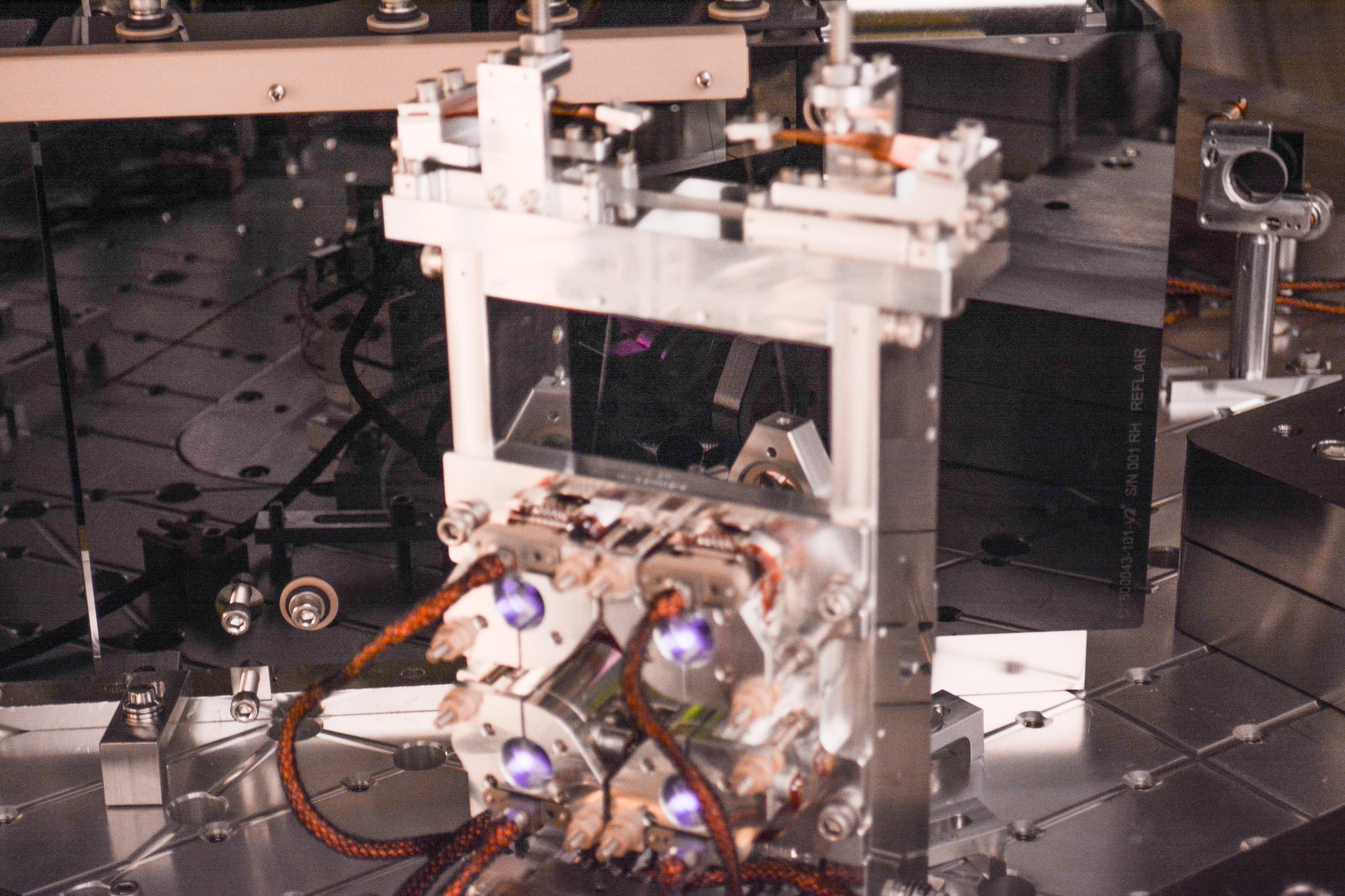
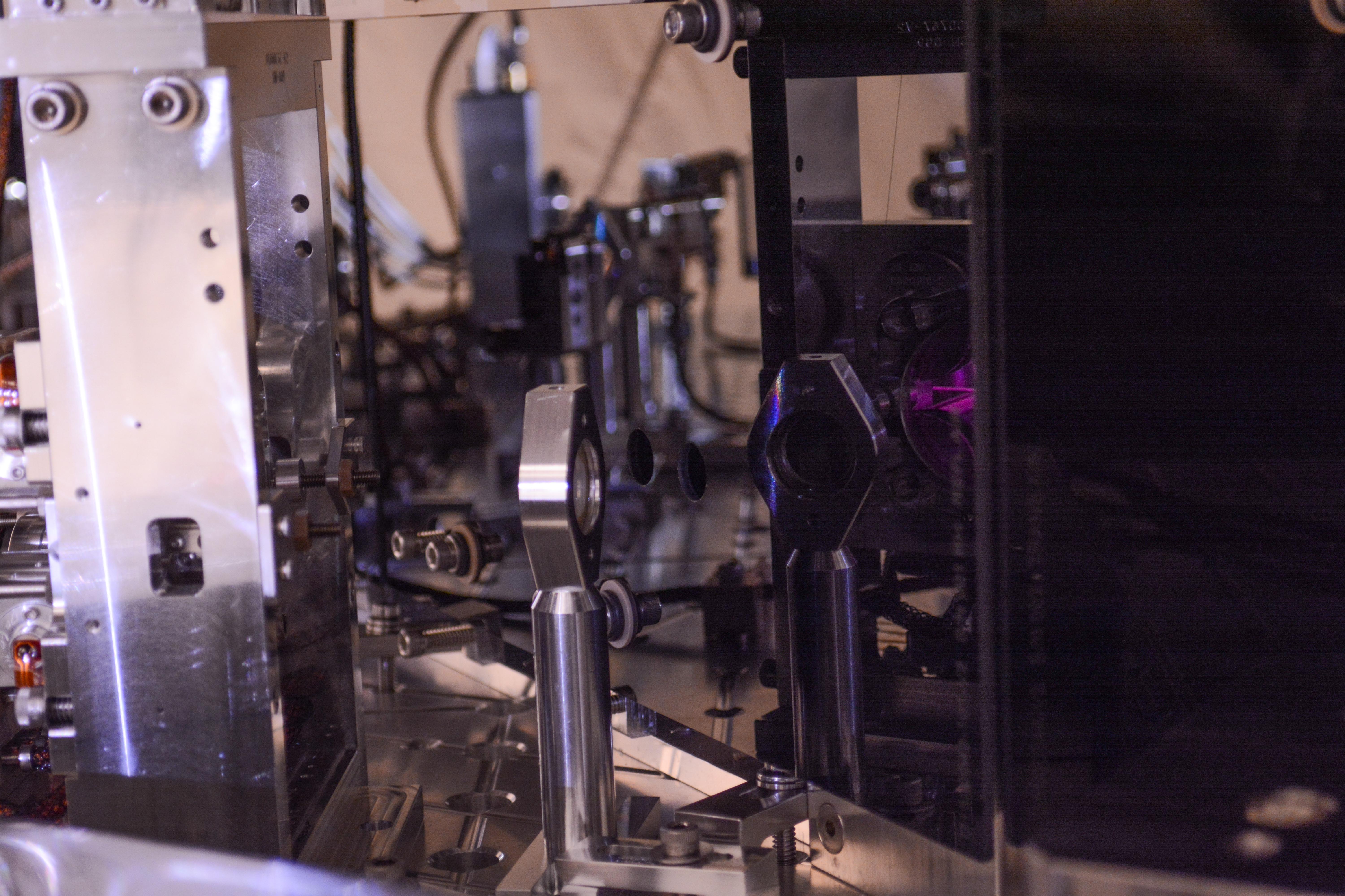
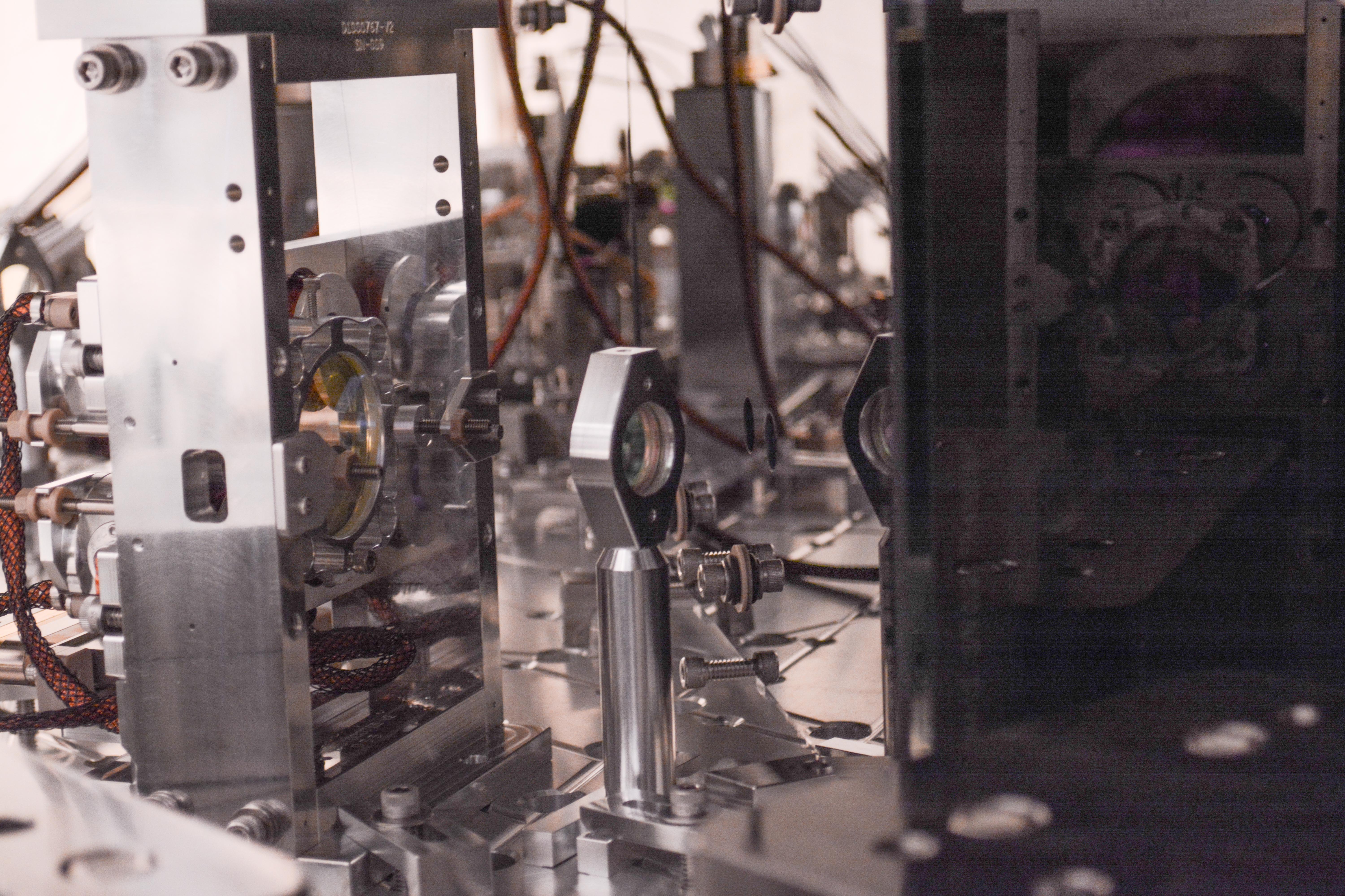
Attached photos of beam at various places.
1) Beam coming out of septum window towards OM1 -- taken as close as possible to the beam height, vertical view
2) Beam coming out of septum window -- camera aligned to the beam as much as possible, horizontal view
3) Beam towards OM1 just before the fast shutter
4) Beam towards OM1 just after the fast shutter
5) Beam reflecting off OM1, in front of the fast shutter
6) Beam reflecting off OM1, behind the fast shutter
7) Beam next to the toaster again after a small alignment change. The beam location stayed pretty much the same.
8) Beam on OM1 (vertical view)
9) Beam on OM1 (horizontal view)
10) Beam on OM2 (vertical view)
11) Beam on OM2 (horizontal view)
12) Beam on OM2 (IR camera)
13) Beam going into OMC, reflects off OM3
14) Beam going into OMC, vertical view
15, 16, 17) OMC input output port area (IR camera looking for scattering)
18) Beam relative to the wire when fast shutter closed
19) OMC refl on beam dump
20) Beam reflects off fast shutter to beam dump
Before-swap pictures were posted in alog 52310.
Oct 11, 2019 Close-out sweep of HAM6 photos are here.
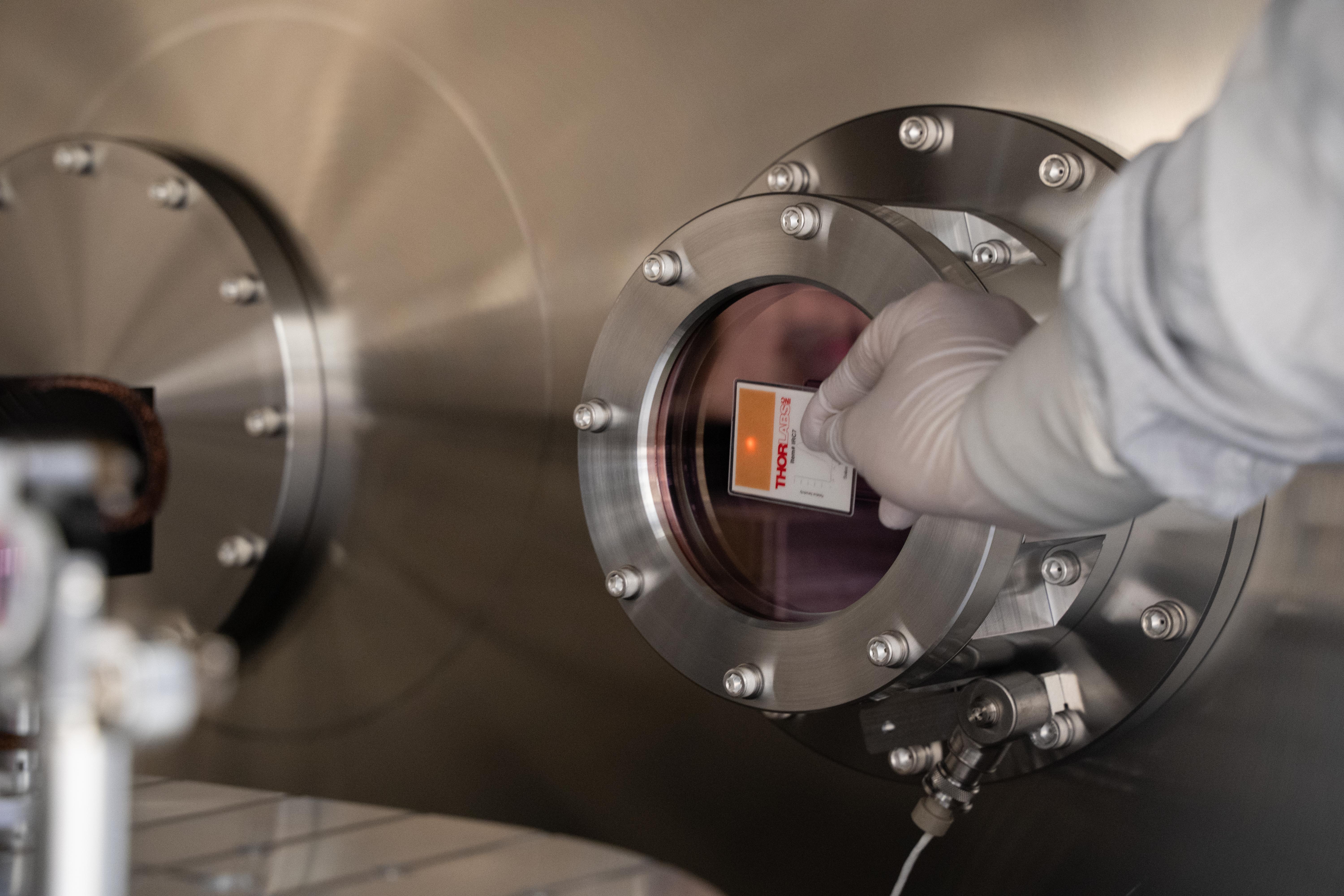
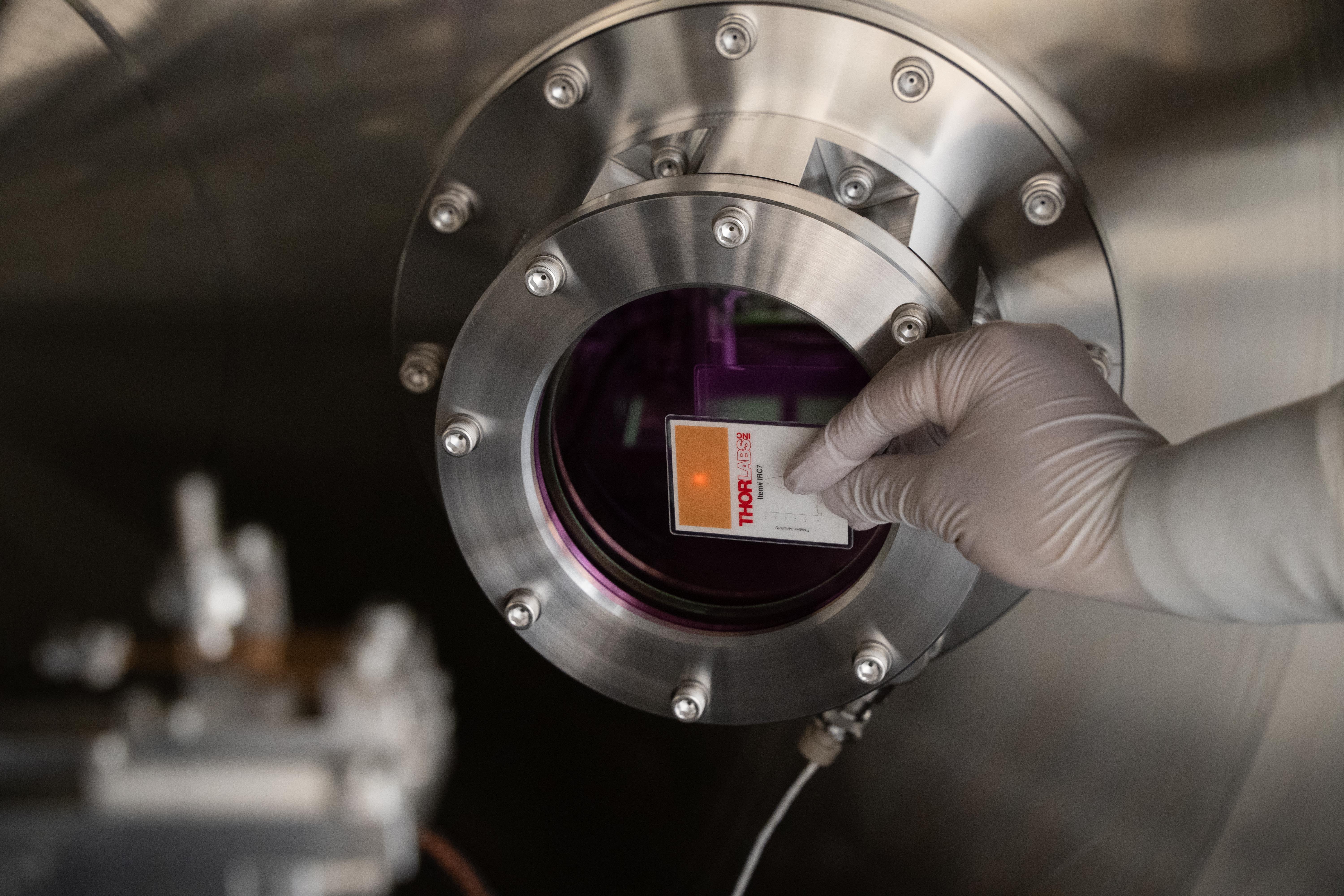
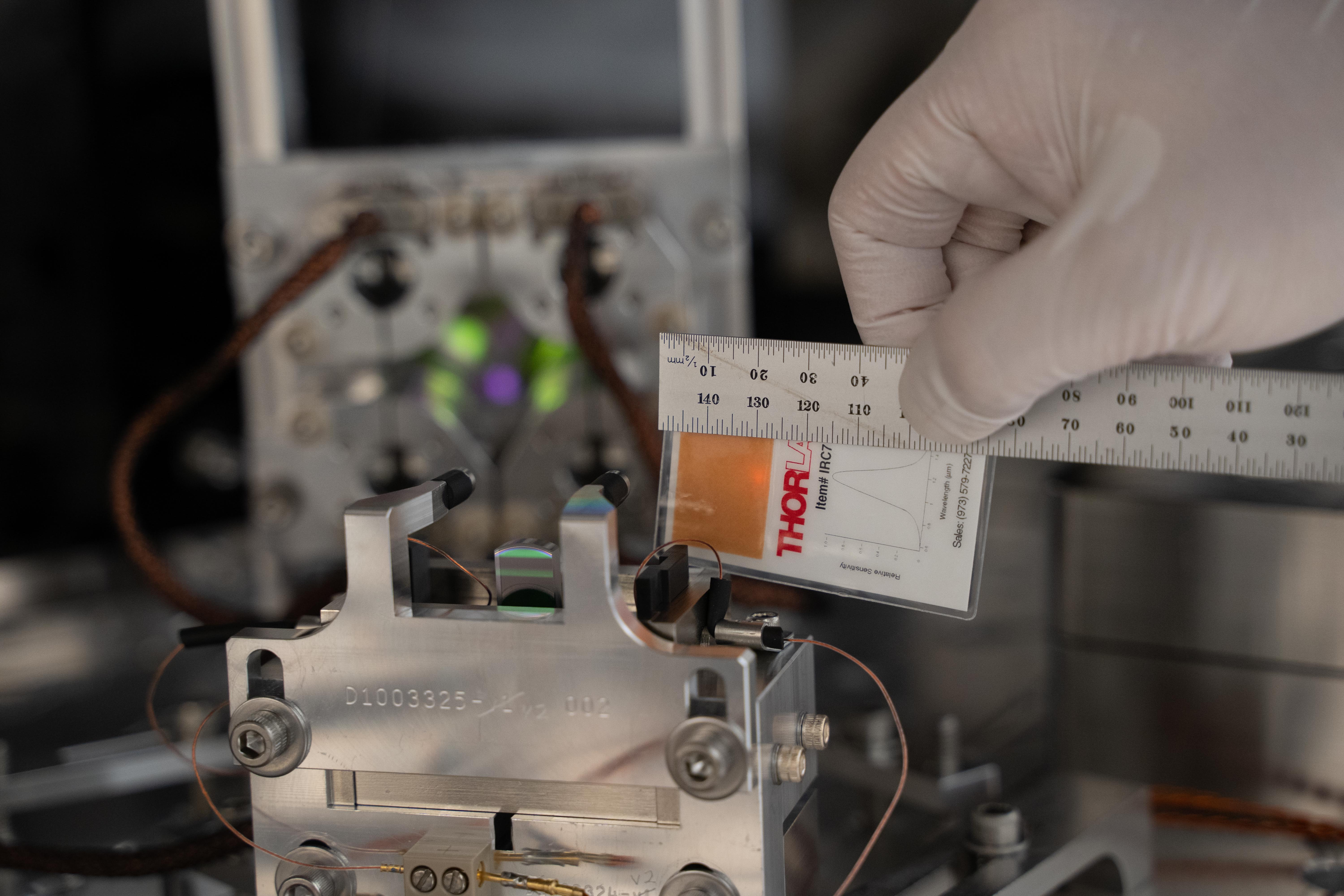
Since Resource Space appears to no longer be functionable/useable, here are some photos of the septum flanges/viewports.
{Chub, Jordan, Gerardo, Chandra}
Because we had to vent MX main volume anyway (to replace leaky turbo GV), we took the opportunity to replace IP10's iLIGO CETEC gate valve with 12" VAT gate valve. As Kyle noted in another aLOG, we started to rough out the volume so we can begin leak checking asap. We will continue pumping tomorrow and finish task by re-installing IP10. IP10 GV is closed to allow for early pump down. Will need to connect a pump cart to ion pump.
Dan B., Cao, TJ
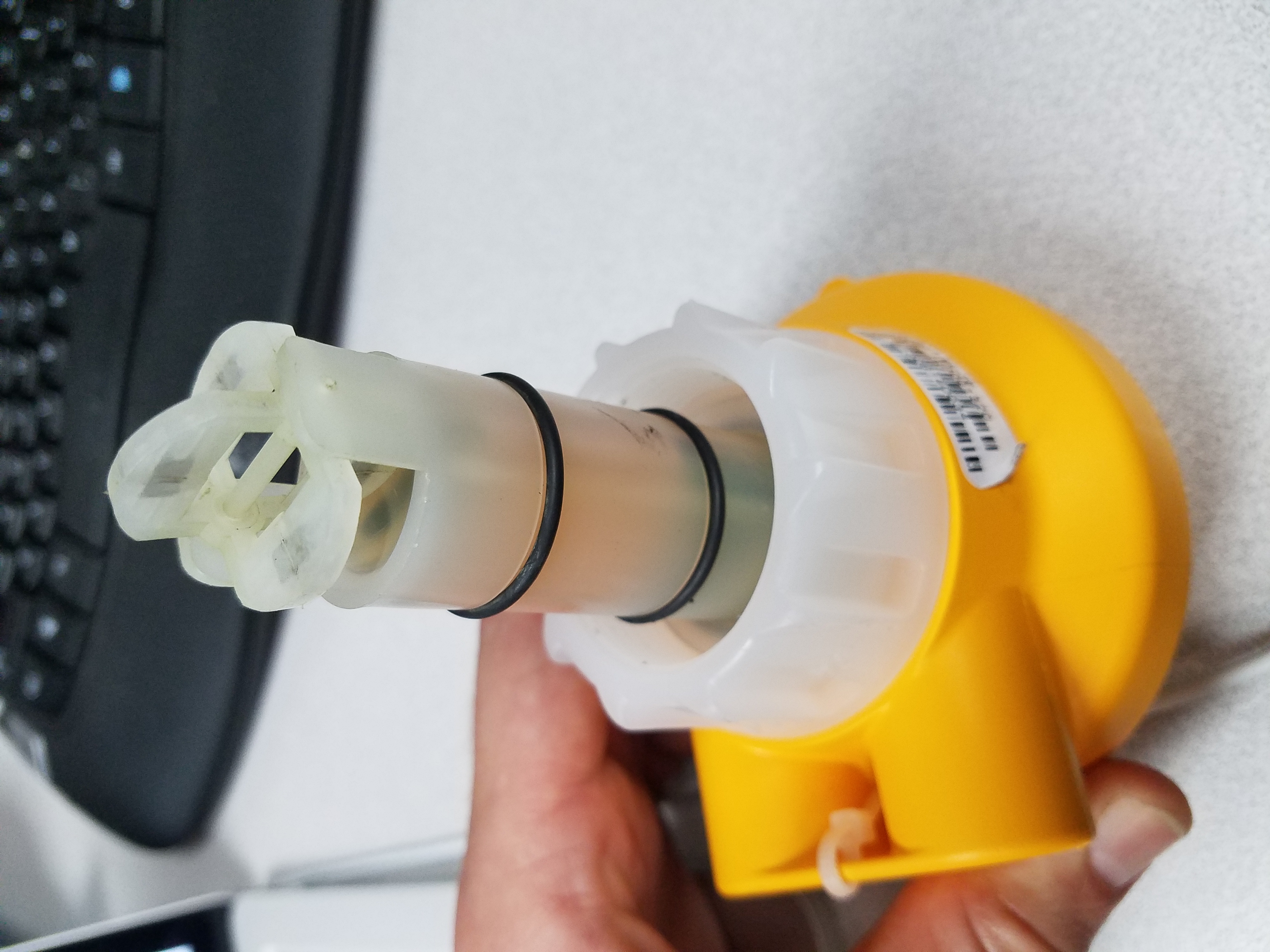
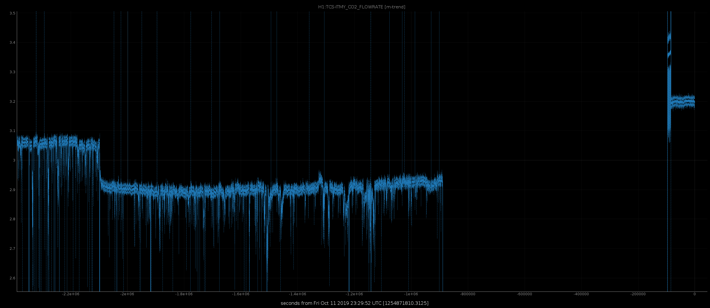
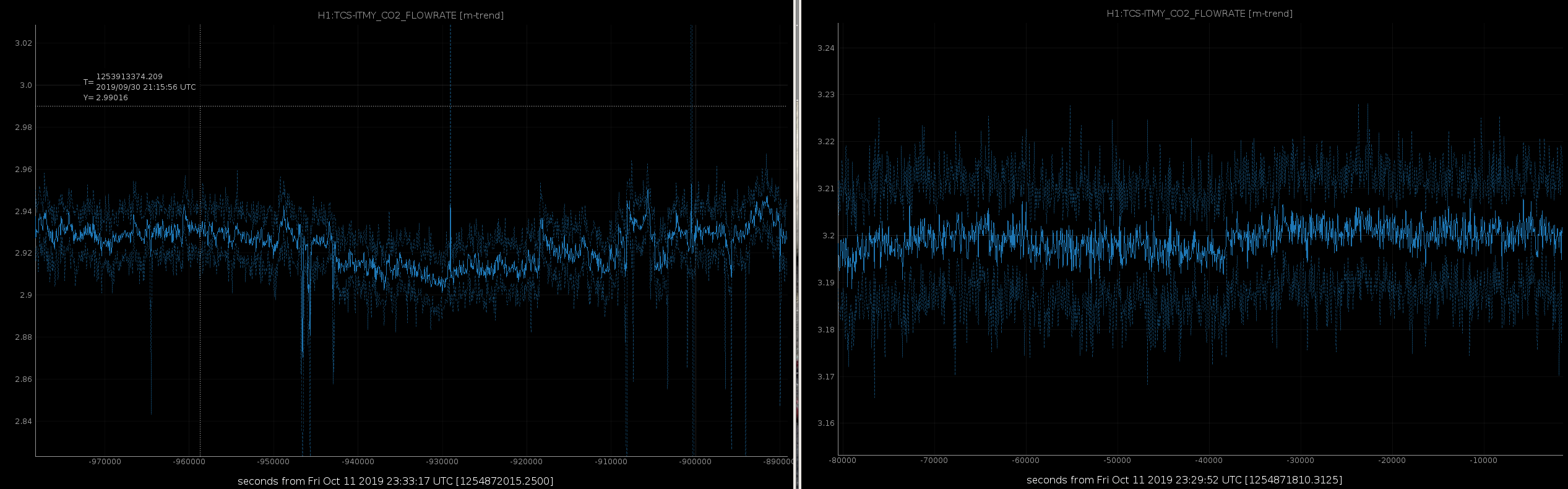
We swapped the TCSY flow meter because it was showing signs that it was going bad again (see alog51823). To do this, we followed the procedure that Betsy outlines in alog32776. We only encountered a few minor issues:
The flow meter that was taken out did not seem as dirty as the pictures of previously removed flow meters (see attachment). Hopefully this helps with some of the flow issues we have seen lately.
Summary of settings:
FLO Unit (Flow Unit) = G/m (default was L/m)
FActor (K-Factor) = 365.00 (default was 60)
AVErage (Average) = 10
SEnSit (Sensitivity) = 0
4 Set (4mA Set Point) = 0 G/m
20 Set (20mA Set Point = 10 G/m (default was 160)
ContrAST (Contrast) = 3
Serial numbers:
Old - 61308140034
New - 61606071363
Gerardo M., Kyle R.
Today we helium leak tested the turbo-side 12" CFF joint of the new VAT valve and found no leak(s) - 1.9 x 10⁻¹⁰ torr*L/sec background/baseline.
We also started to rough pump the X-mid station but the QDP80 soon tripped off due to the electric motor thermistor protection. We reset the thermistor, opened the thermostatic control valve (TCV) one full turn and added an external box fan to cool the QDP80 motor+pump combination. We then resumed rough pumping for another 20 minites or so without a trip before isolating the X-mid from pumping for the night. We will resume pumping down the X-mid in the morning so as to enable helium leak testing the chamber-side of the two new valves installed on the volume (10" VAT turbo isolation gate valve and 12.8" VAT ion pump isolation gate valve.
If the overtemperature trips resurface, we will ask Bubba to start up the X-mid chillers.
TITLE: 10/10 Day Shift: 15:00-23:00 UTC (08:00-16:00 PST), all times posted in UTC
STATE of H1: Planned Engineering
INCOMING OPERATOR: Cheryl
SHIFT SUMMARY:
LOG:
14:57 Timesh at EX
15:00 Vanessa and Karen cleaning in LVEA
15:20 Karen and Vanessa out.
15:30 Chandra out to LVEA
15:48 Gerardo out to LVEA to join Chandra
16:02 Gerardo back
16:03 Gerardo, Chub , and Jordan to MX
16:10 Jeff K out to EX
16:17 Chandra back
16:35 Chandra out to MX
16:33 LVEA still LASER HAZARD
16:37 Jeff K back
16:43 Timesh back
18:58 Jason out to MY
17:01 Corey, Phillipe, ad Gavin out to EX
17:05 Jason back
17:10 HAM6 will be available for in-chamber work after 1:30PM PDT
18:28 Richard out to LVEA to open PSL and ALS light pipes and turn on TCS lasers - LVEA will remain in LASER HAZARD
18:34 Re-Locking of IMC
18:36 IMC locked and WFS are cooking the alignment
18:49 Jeff, Charlie, and Cheryl out to LVEA to inspect for ladder setups.
18:55 Corey, Gavin and Phillipe back
18:57 Jim and Hugh have been at EY fr some time mapping for wind fence
18:59 TCSX having chiller flow issue - TJ investigating -no flow issue: alarm not reset
19:37 Cheryl, Charlie and Jeff back
19:48 TJ, Cao, and Dan out to replace TCSY flow meter.
20:17 Nuts out to LVEA
20:42 Fil out to EX to pull BRS and NCAL cables
21:!5 Nuts out to LVEA
22:06 Niko, Vlad, and Rick headed out to EY to align Pcal input and turn on ALSY
22:09 TJ out to EX to turn on ALSX
22:20 Cheryl out to LVEA to look for a ladder
22:44 Timesh and Gavin out to EX to retrieve equipment
22:46 Cheryl back
Here are trends of the ZM1 actuator requests over O3a, we started the run using most of the yaw range and drifted towards the edge of the range over time. This is a 16 bit DAC, so the full range is +/-32786 counts
There will be a more complete alog about the HAM6 work this afternoon/evening. After aligning the michelson we ran AS centering loops for the single bounce beam to set the alignments of the OMs, then used SRY to set SRM, and injected a seed beam from the squeezer. When we ran the centering loops from AS A/B to the ZMs, ZM1 ends up in a simimlar alignment to where it was at the end of O3a, nearly railed.
PCal team is doing some aligning.
(Corey G., Philippe Nguyen, Gavin Wallace)
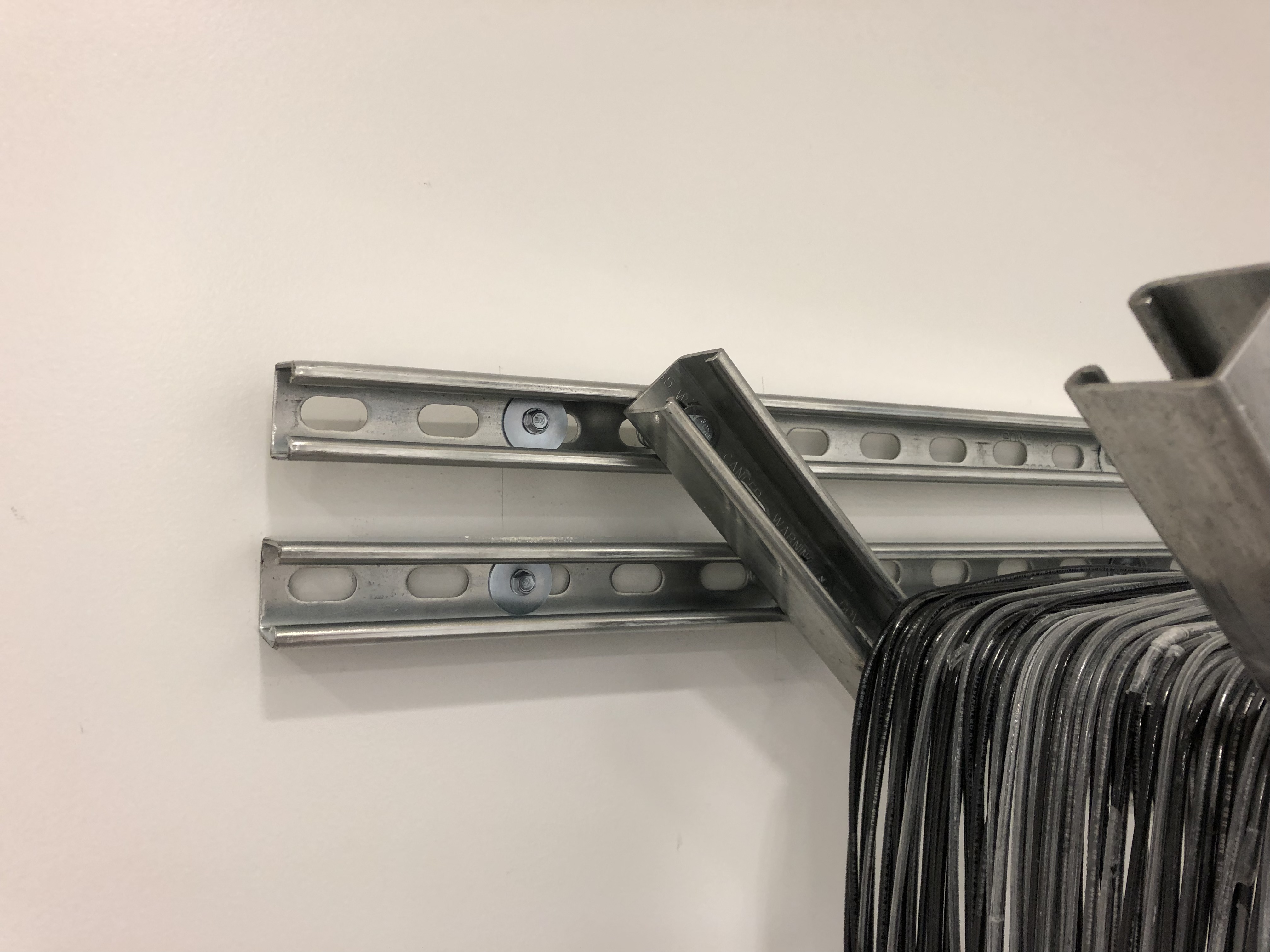
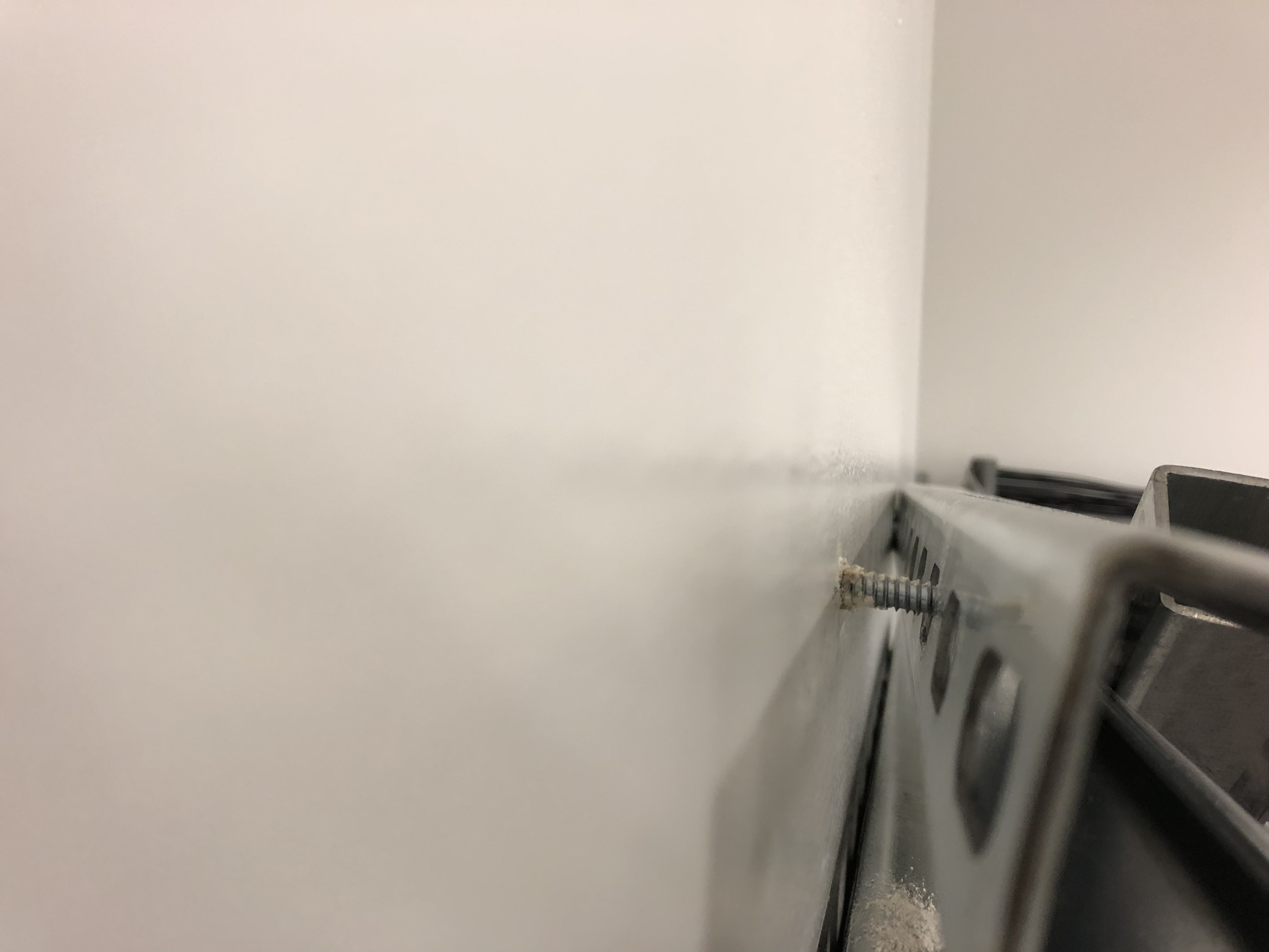
Continued Magnetic Coil installation at EX from yesterday. We improved on our technique and got quite a ways done in an hour. Unfortunately, we had to stop work because we noticed one of the upper corner brackets came undone from the wall (there are a total of 4 screws which are holding these brackets and one of them partially popped out from the wall). This occurred as we were pulling down on the cable to remove any slack in the loop. We notified Richard about this and he mentioned that he will get Ken to re-secure this bracket.
As for status of the coil, we counted how many loops we were able to make, and we had about ~75 turns (LVEA one has about 80 turns), so we we were almost done with using the 2nd spool of wire.
Ken repaired the upper left corner bracket this morning.
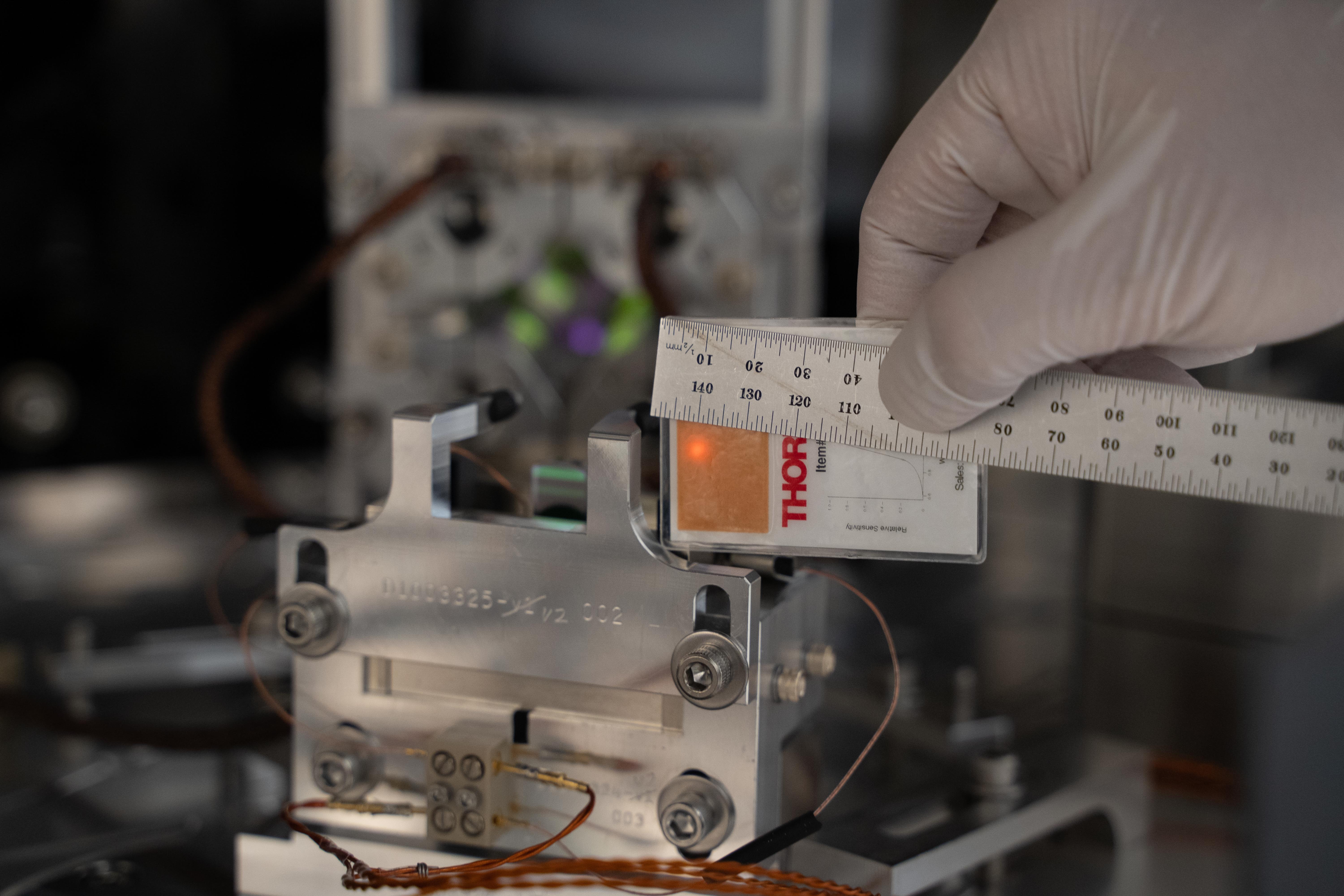
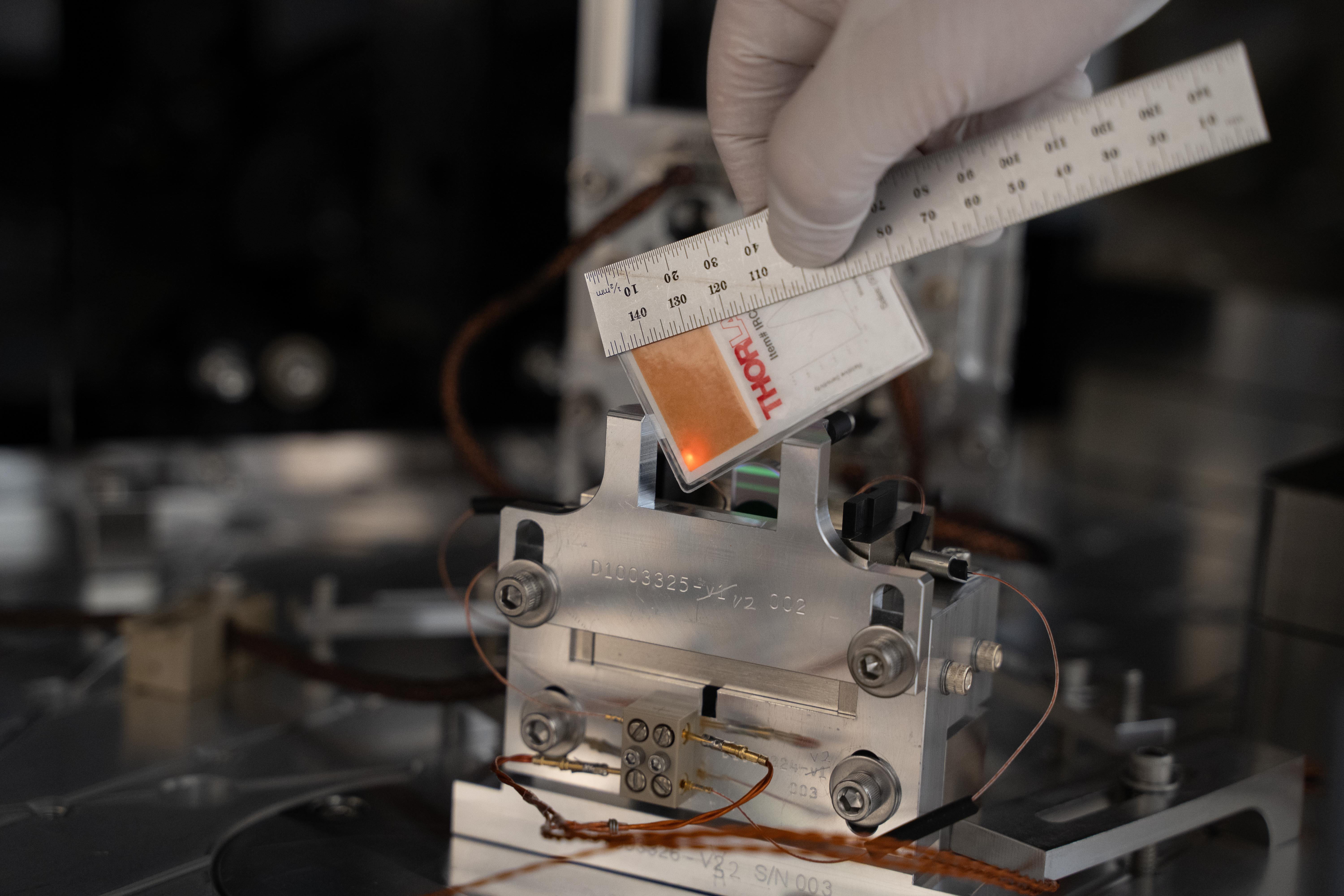
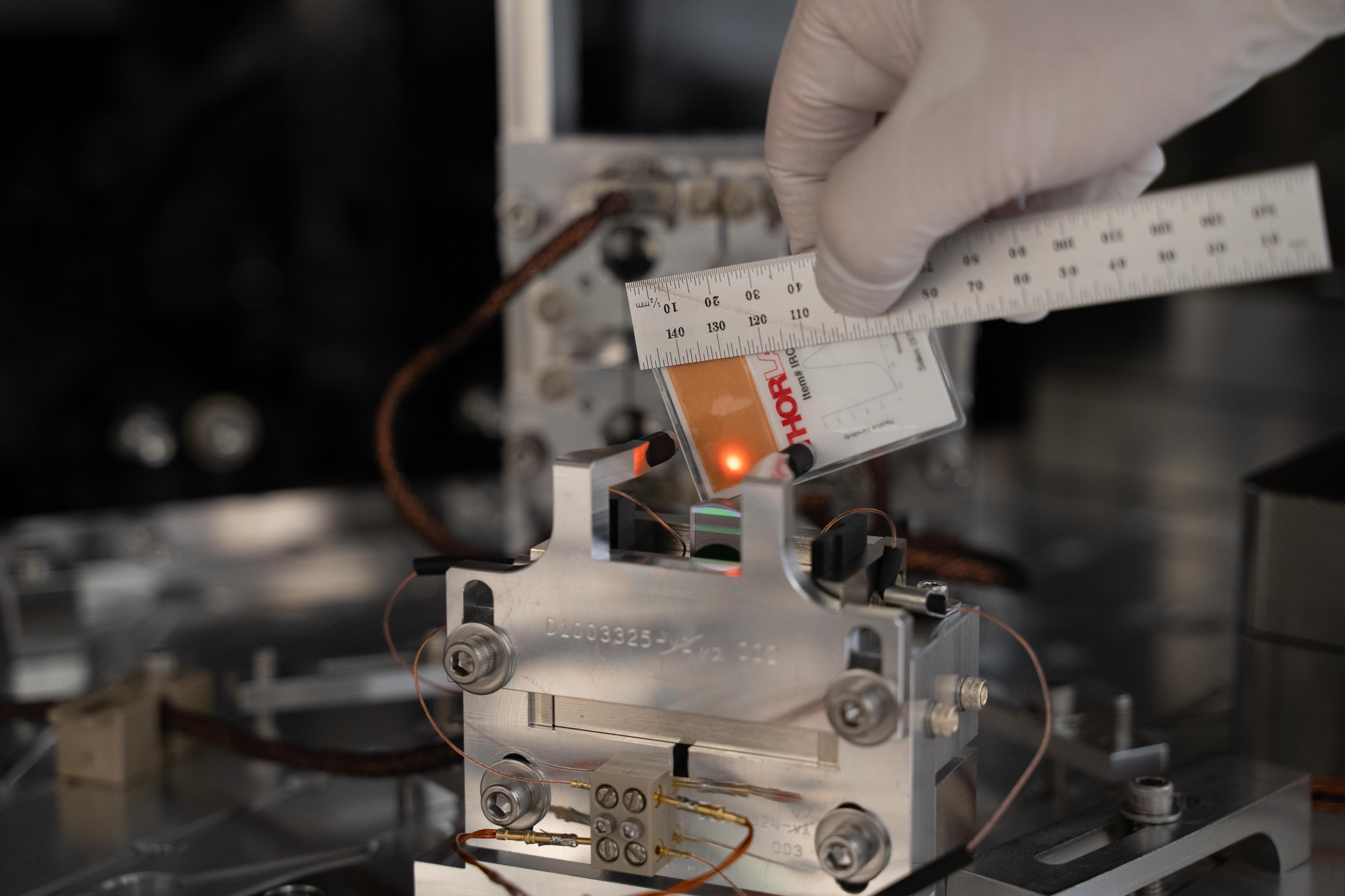
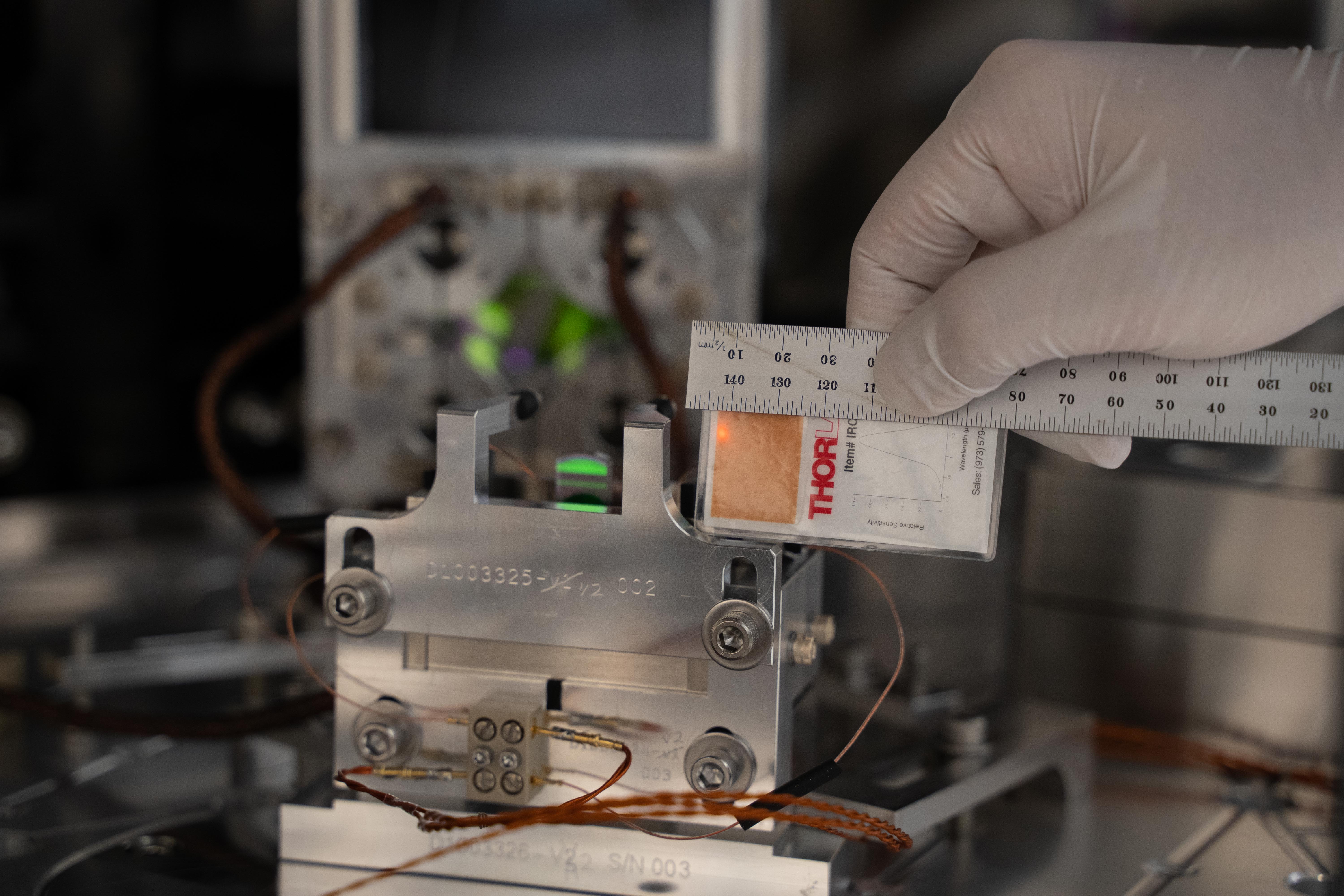
Daniel was seeing no response from the monitor PD for the newly installed ALS pickoff, so I went in really quick to measure the power in, power reflected, and power transmitted from the mirror directing the light into the new fiber (the PD sits after this mirror, see D1300348):
With the power on the PD so low, I removed the 2 ND filters sitting in front of the PD and installed a light pipe (for some measure of stray light control). Daniel now reports that he is seeing a response from the monitor PD, so with the above numbers should be able to calibrate it properly.
While I was in there I labeled both the new pickoff fiber and the spare fiber as such, and changed the label on the newly installed lens to reflect that it was a f=150mm lens (instead of the f=200mm it was previously labeled as). Total time in the enclosure was under 30 minutes, with the laser room environmental controls (lights, AC, and HEPA fans) on for < 10 minutes (the anteroom fans and lights were on for the remainder).
We spun up the new ATH2303 maglev turbo on vertex volume at ~ 550 mTorr, backed by iLIGO QDP80 roughing pump. It took 35 minutes to come up to full speed (31,000 rpm) and foreline rose to 1.6 Torr. Turbo temp fluctuated between 19-22C and electronics 35-42C.
Once we reach hard vacuum (e-3 Torr) and then wait four hours to honor our viewport safety guidelines, HAM6 in-chamber work may resume. I will let the operator know and make a log entry at that point.
that totally sucks.
Great looking vacuum crew! Who cares if the pump sucks.
G. Mansell, D. Sigg, J. Oberling, R. McCarthy, D. Brown, F. Clara
ECR E1900246
WP 8363
Today we switched the ALS fiber distribtion chassis at the ISC racks. We plugged the new PSL pick-off into the chassis and have confirmed that the end-station and squeezer PLL's can lock.
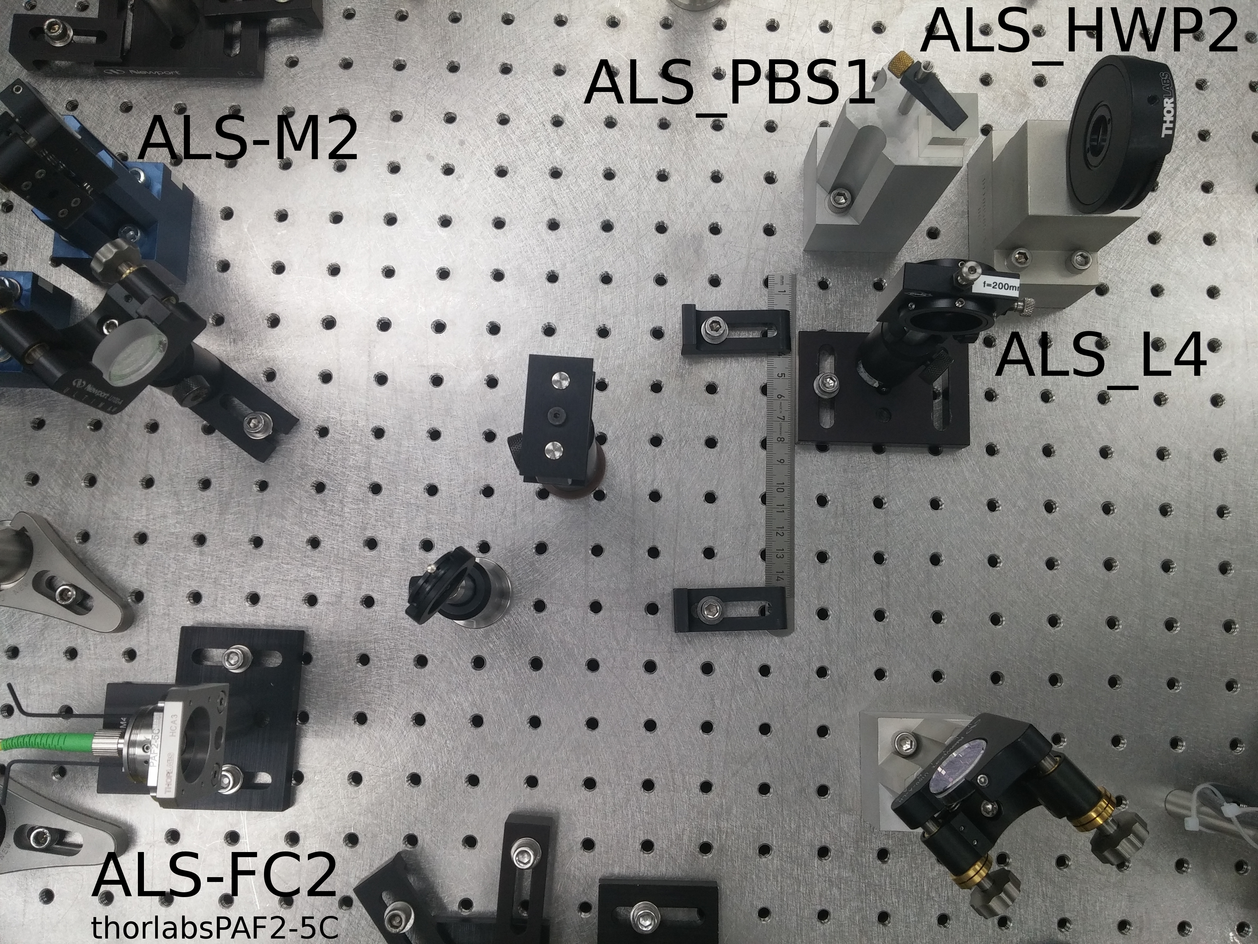
The new pick-off is from the ALS-bypass path, which is after the PMC inside the PSL. Previously Peter K installed a PBS and half waveplate in the ALS bypass, in preparation for the pick off. Last week Jason and I added an f=150mm mode matching lens and coupled ~82% of this light to the fiber which goes out to the ISC racks (specifically ISC R4). I have updated the PSL layout document to reflect this change. And attach a photo of the beam path. Looking at the photo made me realise that we need to update the sticker on that lens mount, it is incorrectly labelled as f=200mm.
We have 50 mW on the pick-off path, with 42 mW transmitted to the chassis. The previous path had only 10mW reaching the chassis.
Jason used the Ophir Vega 10A-V2-SH (SN 122042) to measure the power on the ALS bypass before and after the pick-off:
· Before pickoff: 1.07 W
· After pickoff: 1.01 W
The old ALS path was on transmission of the ref cav, and so had a 160MHz frequency shift relative to the main PSL beam, caused by the double-passed ref cav AOM. Inside the fiber distribution chassis (D1200136) was another 160MHz AOM to undo that frequency shift before the beams were distributed to the end stations. The squeezer beam did not go through the chassis AOM so the 160 MHz shift could be used as a beat note to lock the squeezer laser. The new path in the PSL does not see the ref cav AOM and so is at the PSL carrier frequency. I modified the fiber distribution chassis so the end station beams no longer go through the AOM, while the squeezer path now goes through the AOM. An additional port was also added to delivier light to ISCT1 for Dan's phase camera. Previous and current design splitting ratios below:
| X-arm | Y-arm | Squeezer | Sample | Homodyne | |
| Old chassis | 5% | 5% | 5% | 20% | - |
| New chassis | 10% | 10% | 10% | 5% | 25% |
I have updated the chassis test procedure (E1200140) and test results (E1201087) for the new design.
After installing the new chassis Dan and I measured the power out of each port at the chassis. with 42 mW incoming power from the PSL.
| X-arm | Y-arm | Squeezer | Sample | Homodyne | |
| Actual power out [mW] | 3 | 3.1 | 0.9 | 2.7 | 6.8 |
After the chassis switch I had to re-optimize the fiber polarization paddles to get sufficient PSL light to the end stations. I had tell the end station phase locked loops to ignore the PSL conditions (usually it checks if the ref cav is locked) and with this the X-end PLL (locking the end station ALS laser to the PSL) locked by itself. We will need to modify the PLL contions to check if the PMC is locked.
The Y-end PLL had a problem where the RF beat note power was too high (this was a sneaky problem because the error message reported that there was a noise eater error, but Sheila found the true problem). We increased the max RF power and then it locked. Previously the maximum beat note strength was 6 (... dBm?), Sheila increased it to 8, since the new value is between 6 and 7.
The squeezer TTFSS was trickier to lock. Sheila and Nutsinee had to hand-tune the laser crystal frequency to find the lock point, it was ~300MHz from the expected frequency. This could either be due to temperature excursions in the PSL enclosure, since we had a brief incursion today, or maybe I have put the AOM in the chassis in backwards. The latter problem can be fixed in software.
The PLL/TTFSS auto locker doesn't look at the reference cavity. It only looks at the power of the 2 PDs connected to the distribution chassis. How much do they read? How was the transimpedance adjusted?
Connected the controls cable to the rear of the ALS distribution chassis. This brought the monitors back.
New settings:
| New | Old | |
|---|---|---|
| H1:ALS-C_FIBR_RFMON | 31.5 dBm | 32.2 dBm |
| H1:ALS-C_FIBR_INTERNAL_DC_SPLITTERR | 0.33% | 1% |
| H1:ALS-C_FIBR_INTERNAL_DC_NOMINAL | 0.0147mA | 0.0167mA |
| H1:ALS-C_FIBR_INTERNAL_DC_POWERMON | 33.7 mW | 10-15 mW |
The external PD only shows 20mV. Checked that the transimpedance is 8K, so there is either an open connection or very little light on the PD.
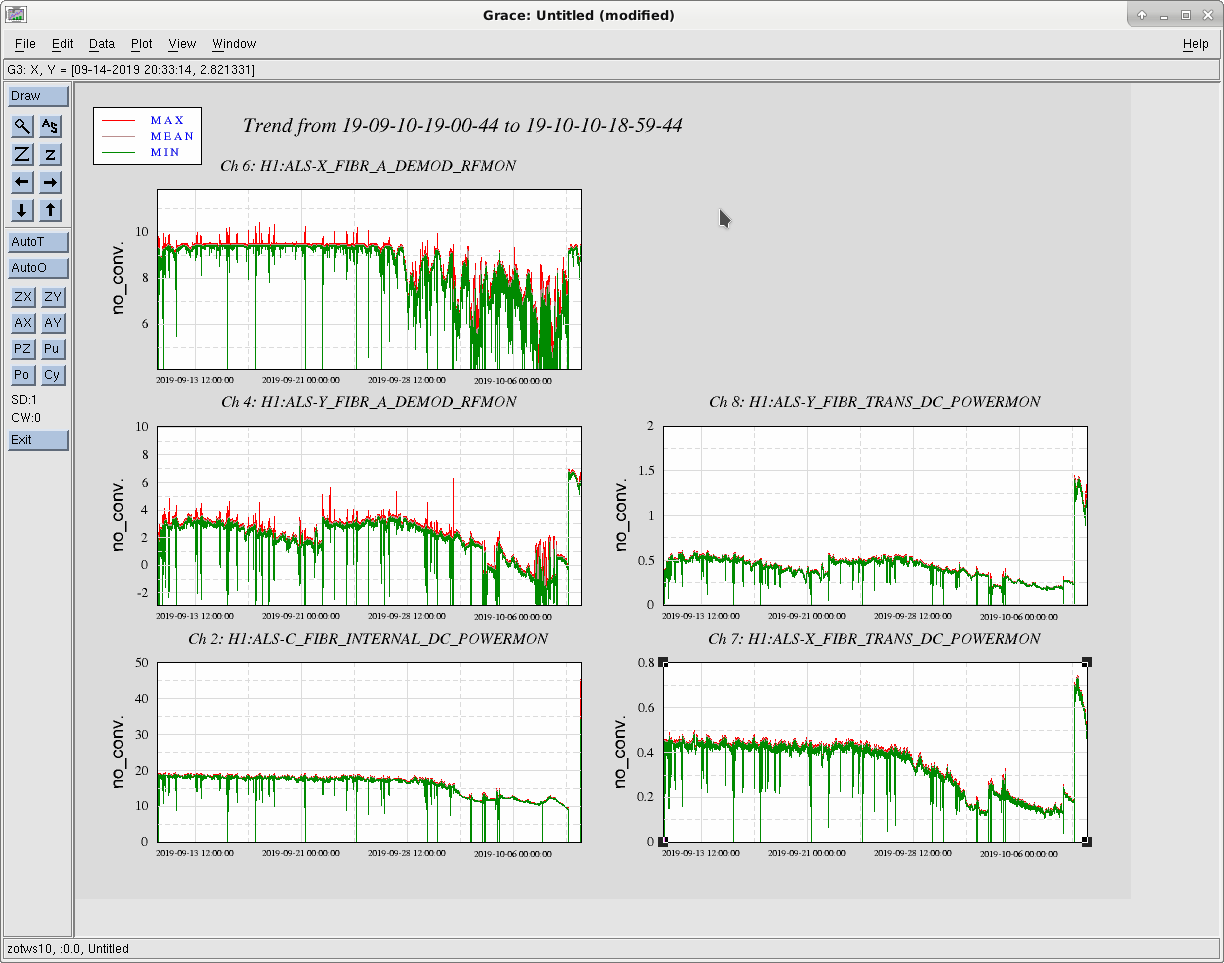
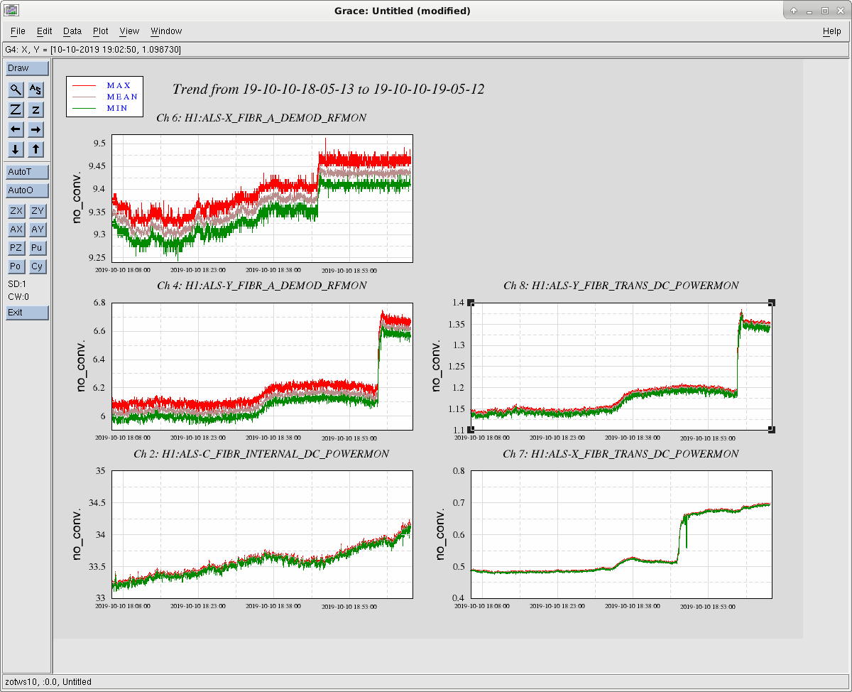
Here is a trend of the end station fiber power PDs and PFD signals. There seems to be about 2.5x power in end Y and 1.6x in end X.
The X end demod readout is pretty much saturated at ~9.5dBm. In the past, we have used a higher than usual RF power as an indication that the laser noiser easter is oscillating. This is probably no longer possible.
The maximum power onto the squeezer laser table seems to be around 0.6mW (H1:SQZ-FIBR_TRANS_DC_POWERMON). However, the beat note strength degrades beyond ~0.45mW. Also, the sign in the squeezer laser locking loop has changed. Before, the squeezr fiber beam was ~158MHz above the laser frequency, now it is ~158MHz below.
Thanks to Jason's work in the PSL (alog 52401), the external PD now works as well.
The new settings are:
| New | Old | |
|---|---|---|
| H1:ALS-C_FIBR_EXTERNAL_DC_OFFSET | +0.017V | 0.000V |
| H1:ALS-C_FIBR_EXTERNAL_DC_RESPONSIVITY | 0.38A/W | 0.36A/W |
| H1:ALS-C_FIBR_EXTERNAL_DC_SPLITTERR | 0.66% | 5.3% |
| H1:ALS-C_FIBR_EXTERNAL_DC_NOMINAL | 0.125mA | 0.565mA |
| H1:ALS-C_FIBR_EXTERNAL_DC_LOW | 0.2mW | 0.5mW |
Nominal power on the PD is 0.333mW (reads 1.03V).
Jason has later completed the relabelling of the lens suggested by Georgia -- see LHO aLOG 52401.
【Craig, Evan】
We took a look at the noise is AS A RF45Q in and out of lock. This sensor is used for dHard and we wanted to see if we could gain some insight into the cross-coupling issues between DARM and the angular loops (some previous insight here and previous decoupling work here). We mostly looked at the sum channel (essentially an rf DARM readout) rather than pitch/yaw. There aren't any stunning conclusions here, but if the sub-10 Hz noise is better understood it might provide some clues about how to make improvements.
We found some nonstationarity in the dark noise (wandering lines). With light on the diode in full lock, in the region 10 Hz to 100 Hz it seems like there is some broadband excess that is not a straightforward optical signal (from DARM or dHard).
We wonder if it would make sense to try more whitening on this sensor, as currently there is only one stage engaged (AS B RF45, which is not used for anything, has three stages engaged and hence better dark noise performance).
Dark noise
The first attachment shows the dark noise versus the in-lock noise of this sensor. During the maintenance period we unlocked the IMC and proceeded to measure the dark noise, and we were surprised to find a slowly wandering line in the vicinity of 4–7 Hz along with its harmonics (measurements in green and magenta). We were again surprised when we looked at the individual Q segments and found different responses to these lines (second attachment). For example, Q1 seems entirely insensitive to the fundamental of this line, but is the most sensitive out of the four quadrants to the harmonics. This second attachment also shows the dark noise of the AS B RF45Q quadrants, but since AS B RF45 has more whitening than AS A RF45, the two diodes do not readily lend themselves to comparison.
We also looked at some past times during maintenance days when it seemed the diodes had no light on them (although the IMC was unlocked); one such time is also plotted in the second attachment. Here there are no wandering lines, but the noise at and below 1 Hz is worse (the whitening settings have not changed, according to time machine). Maybe there was some signal since the IMC was still locked.
In-lock noise
The first attachment again shows the noise in AS A RF45Q sum during the full lock. The spectrum at and below 10 Hz is presumably optical signal (DARM plus other effects). The noise above 100 Hz is white, consistent with shot noise. Between 10 Hz and 100 Hz the high-frequency noise appears to aquire some shape that is not white. This region is not coherent with DARM except near various lines (e.g., the dither lines).
The rough calibration was reckoned as follows. Based on previous estimates of the AS port sideband content and the rough number of 250 mW of power leaving the SRM (via the calibration of AS C into milliwatts and the 800 ppm transmission of OM1), it seems that the 45 MHz beatnote signal should be of order 2 mW. Together with the dc value of the AS A RF45 sum channel in counts (about 10000), this can be used to infer that the total measured noise at high-frequency is about 10−7 mW/Hz1/2.
Comparison with DCPD sum
We also made a comparison of AS A RF45Q against the DCPD sum (third attachment). The rf sensor is scaled to match the dc sensor in the region 5–10 Hz, where the two are highly coherent. Above 10 Hz, the rf sensor's noise dominates over the dc sensor. The interpretation of the noises below 5 Hz is less straightforward. One thing that is apparent is that there are regions of high coherence (e.g., around 0.8 Hz) even though the two sensors show spectra with vastly different amplitudes. The sensors could be seeing the same noise, but with different coupling factors. Alternatively, a sensing noise peculiar to the dc readout (e.g., from the OMC) could be being impressed onto the loop and then witnessed by the rf sensor.
Plots for a longer stretch (6 hours, starting at 2019-09-21 09:00:00) of median-averaged data are also attached, with smaller binwidth. Here the large variability in the low-frequency coherence is more apparent.
A next step would be to run bruco on the DCPD sum and the RF45Q sum to see what the major contributors are at these low frequencies. I tried running bruco on Caltech ldas-pcdev12 (for only 1000 seconds), but it just hangs.
I am also attaching a comparison between AS A and AS B RF45 sums, along with some ADC count comparisions. AS B RF45Q maintains coherence with DARM up to higher frequency and has an overall lower noise floor than AS A RF45Q. AS B has not received the same careful rephasing as AS A (there is some DARM sensitivity in the I quadrature), but nonetheless is phased so that DARM mostly appears in Q.
It is also interesting to note that the low-frequency regions of high coherence with the DCPDs (0.8 Hz, 1.27 Hz, etc.) show up in both quadratures for both AS A and AS B even though (at least in the case of AS A) the phasing minimizes the appearance of DARM in I above 10 Hz.
The ADC count comparisons seem to indicate that turning on two extra whitening stages on AS A will increase the rms from 200 ct to something like 500 ct.
We turned on whitening stages two and three for AS_A_RF45. We did this in lock by switching the DHARD sensor from AS_A_RF45 to AS_B_RF45 with a gain of -1.25 in both the PIT and YAW sensing matrix. Preliminary results suggest no DARM noise improvement, but lowered dark noise in the AS_A sensor above 10 Hz. Noise was lowered by around a factor of 2. Accepted this change into the SDF, and are back to observing.
There was actually a bit of improvement in DARM between 15 and 20 Hz, though it's hard to see without sufficient averaging.
I took an hour of "before" data starting at 2019-09-27 17:30:00 and an hour of "after" data starting at 2019-09-27 20:25:00 and median-averaged it. The plots are attached (I omitted the DARM / dHard yaw coherence to keep the plot from getting overcrowded -- the overall coherence is lower than the pitch DOF). The improvement is subtle, but it's there, particularly at 19 Hz. The changes in coherence and in noise level are roughly consistent with the noise at 19 Hz being dominated by angular fluctuation.
Nothing is particularly surprising here given the previous noise budgeting injections.