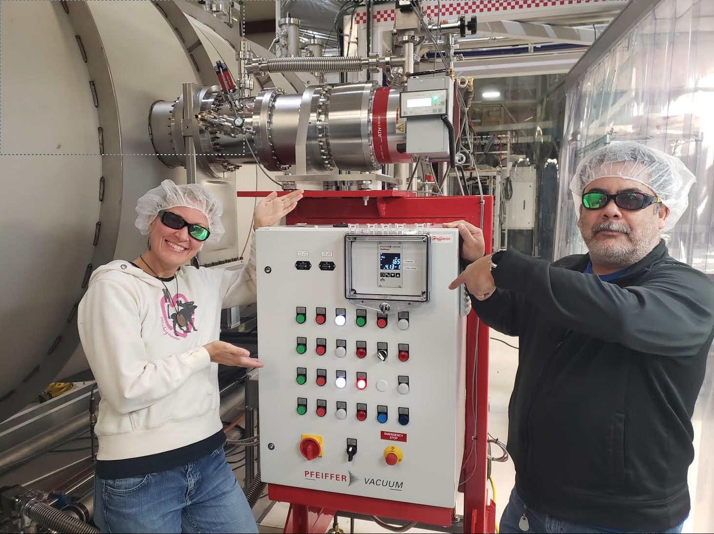
Vertex has reached "hard vacuum" and will be cleared for in-chamber and viewport work at 1:30 pm local time.
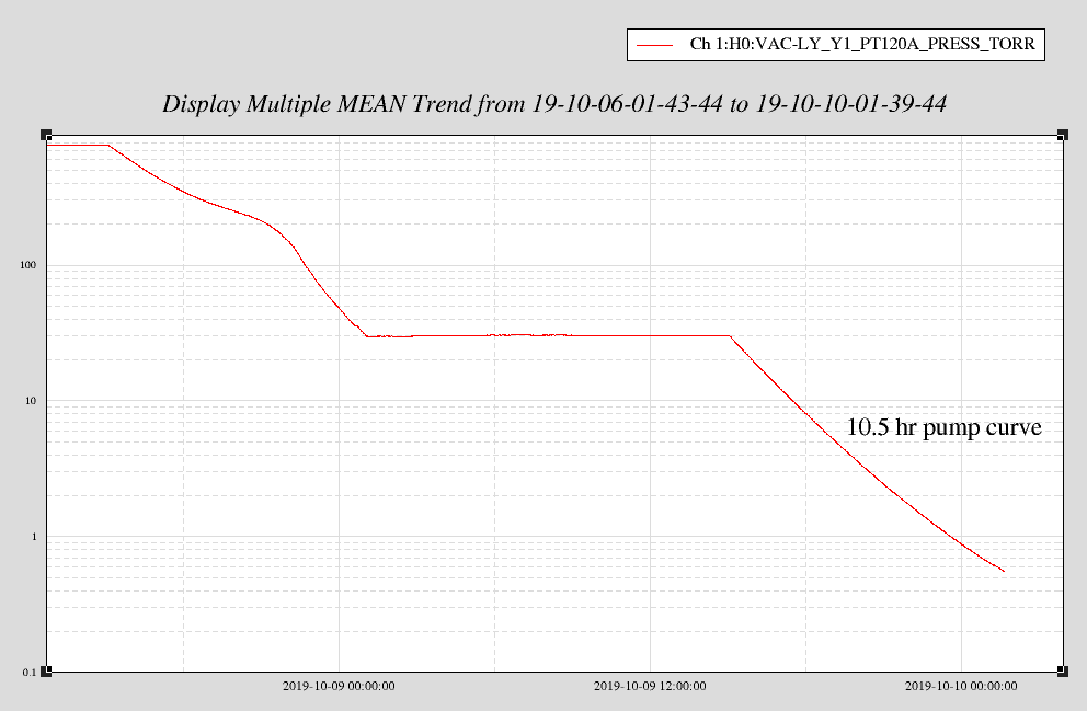
We spun up the new ATH2303 maglev turbo on vertex volume at ~ 550 mTorr, backed by iLIGO QDP80 roughing pump. It took 35 minutes to come up to full speed (31,000 rpm) and foreline rose to 1.6 Torr. Turbo temp fluctuated between 19-22C and electronics 35-42C.
Once we reach hard vacuum (e-3 Torr) and then wait four hours to honor our viewport safety guidelines, HAM6 in-chamber work may resume. I will let the operator know and make a log entry at that point.
that totally sucks.
Great looking vacuum crew! Who cares if the pump sucks.
(Corey G., Philippe Nguyen, Gavin Wallace)
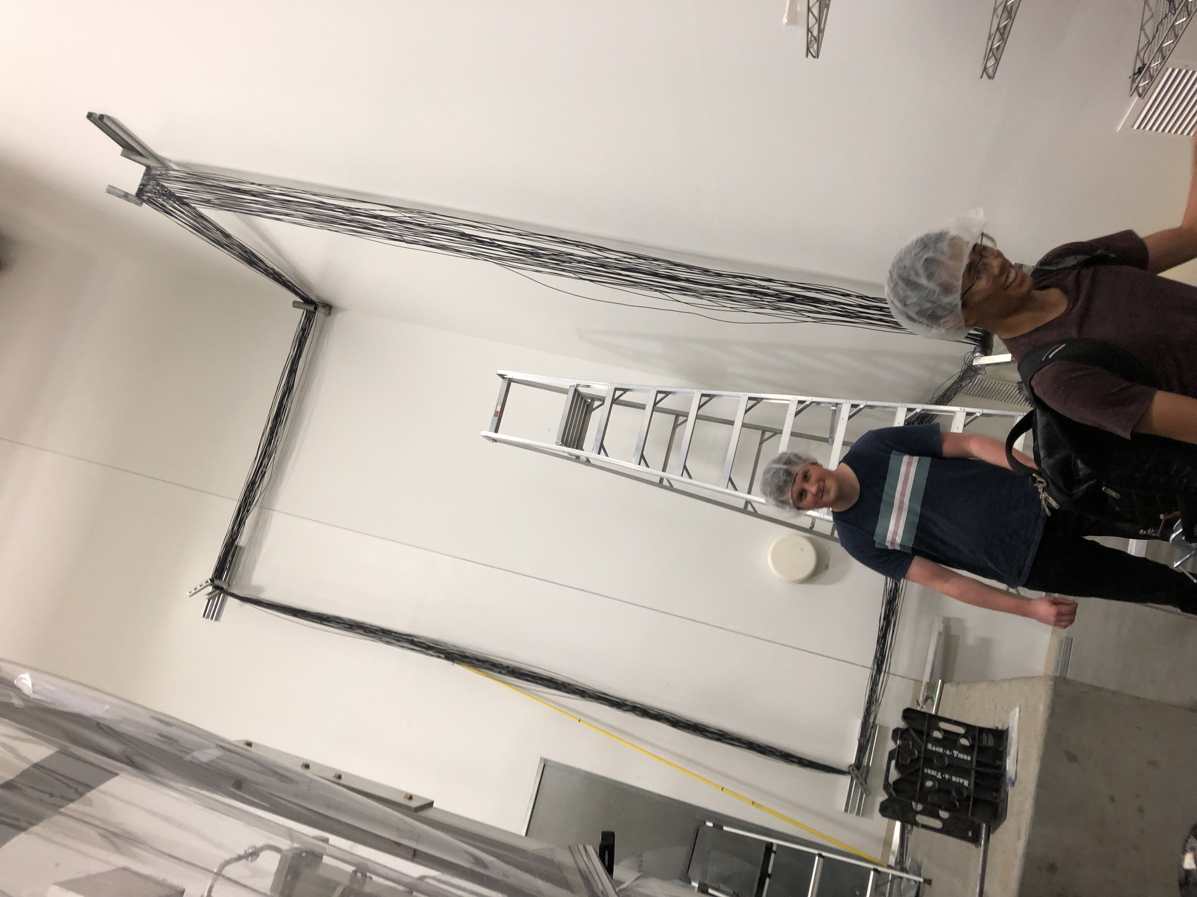
Yesterday installation (WP#8409) of the large PEM Magnetic Coil at EX begun (coil consists of about 5000' of wire!). The first coil was installed in the LVEA in Aug 2018 (alog#43406). Yesterday we used up an entire spool of wire which turns out to be about 40turns (we are aiming for 80 turns & hope to finish up today). Attached is a photo (thumbnail is sideways, but main pic is good) of a satisfied Gavin & Philippe walking away from our 40 turns which took us about 3hrs. NOTE: this installation is different from the LVEA in that the corner is a smaller 90deg for the walls (vs an easier 270deg for the LVEA). Took us a while to get a technique down, but we were good by around turn #5).
As the pressure on the X1 beam tube increases, I have correspondingly increased the cell phone alarm levels. LX-PT144B to 2.0e-08Torr and MX-PT343B to 3.0e-08Torr
TITLE: 10/10 Day Shift: 15:00-23:00 UTC (08:00-16:00 PST), all times posted in UTC
STATE of H1: Planned Engineering
OUTGOING OPERATOR: Patrick
CURRENT ENVIRONMENT:
SEI_CONF state: SC_OFF_NOBRSXY
Wind: 9mph Gusts, 7mph 5min avg
Primary useism: 0.02 μm/s
Secondary useism: 0.11 μm/s
QUICK SUMMARY:
HAM6 STANDOWN STILL IN EFFECT - Exposed viewport on septum plate while doors are off.
Jason inspected the water lines in the PSL enclosure and under the table. He reported no drips or leaks. There are some bulging in a couple of the red lines at the filter housings, but these have not changed since the last inspection. There are no plans at this point to change out these lines, as the plumbing system is to be overhauled after O3. I found no issues or problems with the lines or filter housings in the chiller room. Closing FAMIS #13088
made some DCPD cross correlation plots to compare with LLO.
Time was from gps=1252872096 with duration 2954 seconds, when there was no squeezing and no glitches. With a 1 Hz binwidth, this corresponds to 2954 effective averages, or a factor of 54 of uncorrelated noise suppression.
Seems like our correlated noise is close to the thermal noise floor at 200 Hz, similar to Livingston.
Something correlated is going on at 1.5 kHz.
We were suspicious of the photodetector dark noise curve, as it cuts through at nearly the right amplitude. It is uncorrelated, though, and should integrate away.
I checked the dark noise cross spectrum of the DCPDs now, when no correlation should be present (third attachment).
Some correlated dark noise seems to exist at HF, but it's not enough to explain the correlated spectrum we see at Hanford.
Probably the intensity noise is lower at the time of this spectrum than at the time we took the trace for the noisebudget. We will continue to observe this when we commission the last week of October.
Code lives in /ligo/home/craig.cahillane/Git/o3-commissioning-paper/code/lho_xcor.py
At 550 mTorr, I valved out the QDP80 for the night. We will be ready to spin up the **new** turbo first thing tomorrow morning. Drum roll please!
G. Mansell, D. Sigg, J. Oberling, R. McCarthy, D. Brown, F. Clara
ECR E1900246
WP 8363
Today we switched the ALS fiber distribtion chassis at the ISC racks. We plugged the new PSL pick-off into the chassis and have confirmed that the end-station and squeezer PLL's can lock.
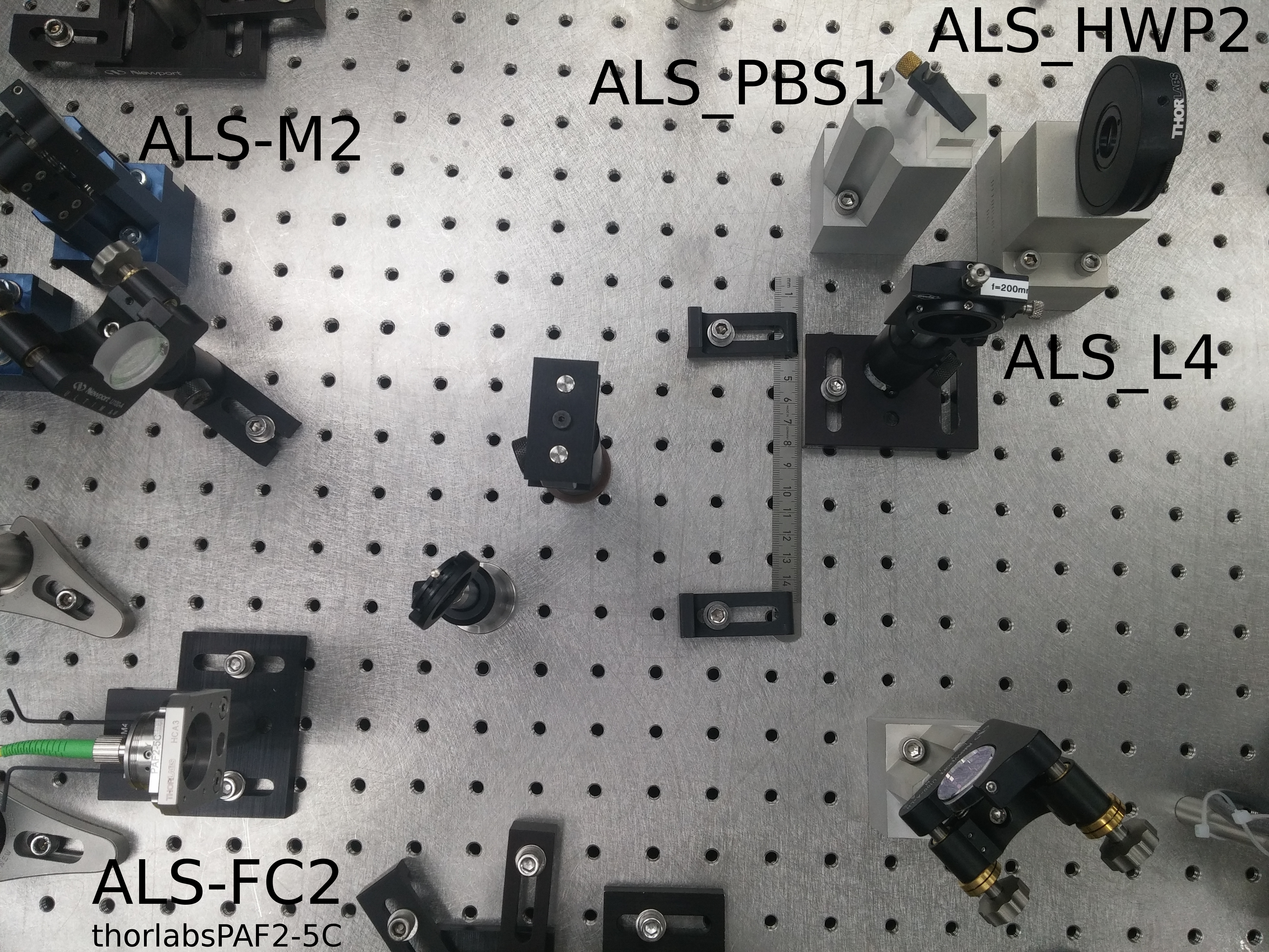
The new pick-off is from the ALS-bypass path, which is after the PMC inside the PSL. Previously Peter K installed a PBS and half waveplate in the ALS bypass, in preparation for the pick off. Last week Jason and I added an f=150mm mode matching lens and coupled ~82% of this light to the fiber which goes out to the ISC racks (specifically ISC R4). I have updated the PSL layout document to reflect this change. And attach a photo of the beam path. Looking at the photo made me realise that we need to update the sticker on that lens mount, it is incorrectly labelled as f=200mm.
We have 50 mW on the pick-off path, with 42 mW transmitted to the chassis. The previous path had only 10mW reaching the chassis.
Jason used the Ophir Vega 10A-V2-SH (SN 122042) to measure the power on the ALS bypass before and after the pick-off:
· Before pickoff: 1.07 W
· After pickoff: 1.01 W
The old ALS path was on transmission of the ref cav, and so had a 160MHz frequency shift relative to the main PSL beam, caused by the double-passed ref cav AOM. Inside the fiber distribution chassis (D1200136) was another 160MHz AOM to undo that frequency shift before the beams were distributed to the end stations. The squeezer beam did not go through the chassis AOM so the 160 MHz shift could be used as a beat note to lock the squeezer laser. The new path in the PSL does not see the ref cav AOM and so is at the PSL carrier frequency. I modified the fiber distribution chassis so the end station beams no longer go through the AOM, while the squeezer path now goes through the AOM. An additional port was also added to delivier light to ISCT1 for Dan's phase camera. Previous and current design splitting ratios below:
| X-arm | Y-arm | Squeezer | Sample | Homodyne | |
| Old chassis | 5% | 5% | 5% | 20% | - |
| New chassis | 10% | 10% | 10% | 5% | 25% |
I have updated the chassis test procedure (E1200140) and test results (E1201087) for the new design.
After installing the new chassis Dan and I measured the power out of each port at the chassis. with 42 mW incoming power from the PSL.
| X-arm | Y-arm | Squeezer | Sample | Homodyne | |
| Actual power out [mW] | 3 | 3.1 | 0.9 | 2.7 | 6.8 |
After the chassis switch I had to re-optimize the fiber polarization paddles to get sufficient PSL light to the end stations. I had tell the end station phase locked loops to ignore the PSL conditions (usually it checks if the ref cav is locked) and with this the X-end PLL (locking the end station ALS laser to the PSL) locked by itself. We will need to modify the PLL contions to check if the PMC is locked.
The Y-end PLL had a problem where the RF beat note power was too high (this was a sneaky problem because the error message reported that there was a noise eater error, but Sheila found the true problem). We increased the max RF power and then it locked. Previously the maximum beat note strength was 6 (... dBm?), Sheila increased it to 8, since the new value is between 6 and 7.
The squeezer TTFSS was trickier to lock. Sheila and Nutsinee had to hand-tune the laser crystal frequency to find the lock point, it was ~300MHz from the expected frequency. This could either be due to temperature excursions in the PSL enclosure, since we had a brief incursion today, or maybe I have put the AOM in the chassis in backwards. The latter problem can be fixed in software.
The PLL/TTFSS auto locker doesn't look at the reference cavity. It only looks at the power of the 2 PDs connected to the distribution chassis. How much do they read? How was the transimpedance adjusted?
Connected the controls cable to the rear of the ALS distribution chassis. This brought the monitors back.
New settings:
| New | Old | |
|---|---|---|
| H1:ALS-C_FIBR_RFMON | 31.5 dBm | 32.2 dBm |
| H1:ALS-C_FIBR_INTERNAL_DC_SPLITTERR | 0.33% | 1% |
| H1:ALS-C_FIBR_INTERNAL_DC_NOMINAL | 0.0147mA | 0.0167mA |
| H1:ALS-C_FIBR_INTERNAL_DC_POWERMON | 33.7 mW | 10-15 mW |
The external PD only shows 20mV. Checked that the transimpedance is 8K, so there is either an open connection or very little light on the PD.
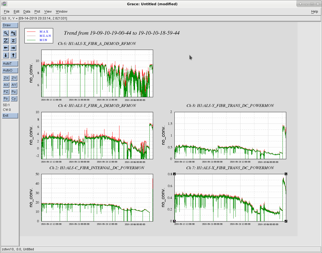
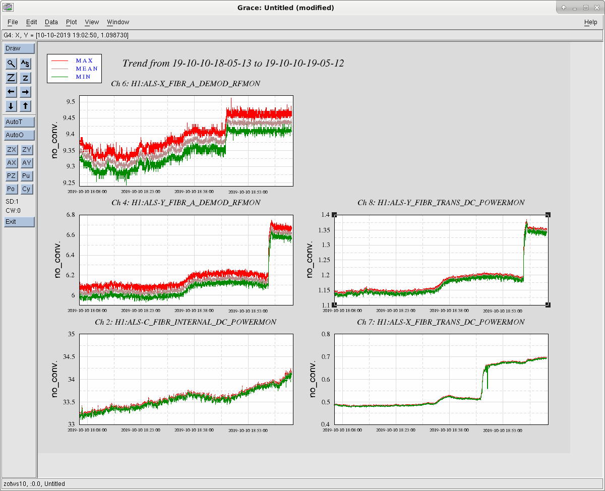
Here is a trend of the end station fiber power PDs and PFD signals. There seems to be about 2.5x power in end Y and 1.6x in end X.
The X end demod readout is pretty much saturated at ~9.5dBm. In the past, we have used a higher than usual RF power as an indication that the laser noiser easter is oscillating. This is probably no longer possible.
The maximum power onto the squeezer laser table seems to be around 0.6mW (H1:SQZ-FIBR_TRANS_DC_POWERMON). However, the beat note strength degrades beyond ~0.45mW. Also, the sign in the squeezer laser locking loop has changed. Before, the squeezr fiber beam was ~158MHz above the laser frequency, now it is ~158MHz below.
Thanks to Jason's work in the PSL (alog 52401), the external PD now works as well.
The new settings are:
| New | Old | |
|---|---|---|
| H1:ALS-C_FIBR_EXTERNAL_DC_OFFSET | +0.017V | 0.000V |
| H1:ALS-C_FIBR_EXTERNAL_DC_RESPONSIVITY | 0.38A/W | 0.36A/W |
| H1:ALS-C_FIBR_EXTERNAL_DC_SPLITTERR | 0.66% | 5.3% |
| H1:ALS-C_FIBR_EXTERNAL_DC_NOMINAL | 0.125mA | 0.565mA |
| H1:ALS-C_FIBR_EXTERNAL_DC_LOW | 0.2mW | 0.5mW |
Nominal power on the PD is 0.333mW (reads 1.03V).
Jason has later completed the relabelling of the lens suggested by Georgia -- see LHO aLOG 52401.
Chiara and Jenne.
Work permit 8410
Experiment proposal on DCC T1900656
As a first step of the experiment, we prepared the front end models to send a cps signal from HAM2 to HAM3 to set an additive offset. This will help to reduce the differential motion between the two chambers and to improve IMCL and PRCL signals.
To do it, we had to modify the ISI HAM2 model which has a library part in the common directory, used also by the other HAMs. We took CPS_X just before it is summed with gs13 and sent it to the top level of the model. Then we used a SHMEM bridge to send it to HAM3, connecting it to the SUS_OFFLOAD_X. Adding another output to the library part means that it is also present in the othe HAM models. So this output has been connected to ground for HAM3, HAM4, HAM5 and HAM6.
Since the library part is in the common directory, we also checked that it is not used by LLO.
We compiled all the HAM models and check that there are no errors; we did not do the install or reboot. We checked all our changes into the svn.
In coordination with people working on alignment, we are going to test the new models during next week.
Gerardo M., Kyle R.
Today we vented the X-mid station, removed the (circa 1997) defunct (leaking, turbo side) 10" CETEK gate valve and replaced it with a new 10" VAT gate valve. We didn't do any leak testing but we did back the turbo with a leak detector and are running both over night. We will start tomorrow off by helium leak testing the turbo-side CF joint but will have to wait until the 2500 l/s ion pump isolation gate gets replaced (Chandra, Chub, Jordan) and the X-mid is pumped back down before we can leak test the tube-side CF joint.
Also, I ran the X-mid QDP 80 pump all day. I confirmed that the chilled water is circulating at the X-mid but it isn't clear whether the chillers are running as the supply temp measures 52F. Regardless, ambient cooling of the circulating water supply should suffice for our needs as we are now in the fall season.
I went out to MX at end of day and noticed a small dripping leak at the water in/out connections of turbo, so I spun it down and valved out chilled water for the night. Raised safety valve pressure set point to 5e-2 Torr. Leak checker is still valved in and reading e-10 Torr-L/s range.
On Monday, old HAM6 OMC path septum window was uninstalled. We measured the wedge angle of that window using a laser pointer in the optics lab.
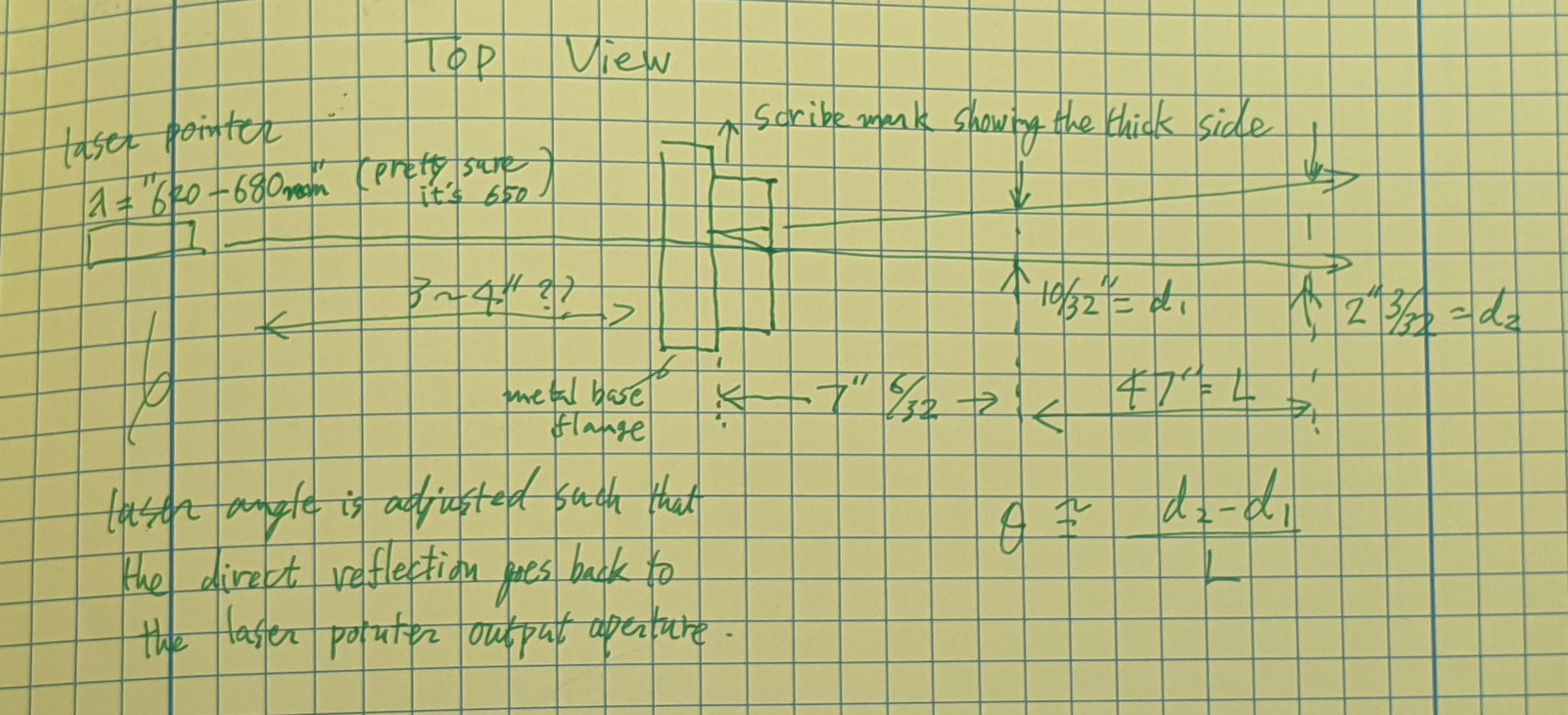
See attached for the setup. We used an eye safe lasr pointer that passed Peter King's inspection in the optics lab. We were clearly able to see the direct transmission and the first ghost beam, so we just measured the distance between these two beams at two different locations, and derived the relative angle between these two beams, from which we calculated the wedge angle.
The result is w=0.745+-0.022 deg.
See the attached comments for the details of the measurement and the calculation.
The spec is 0.75+-0.02 deg (D1101005) so this seems to be as per spec after all, despite that in the past we believed this to be more like 0.9 deg. (See the history comment attached to this one.)
Oh, and we confirmed that the mark on the flange was on the thickest side, as per the drawings D1101092 and D1101005.
Setup, Measurement and Calculation details.
The incident angle on the first surface of the viewport was adjusted so the return beam goes back into the laser output aperture. I clain the incident angle to be 0+-10mrad, which hardly affects the result in any meaningful way.
The angle between the straight shot beam and the first ghost beam, theta, was measured using the distance between two beams measured at two different locations. Distance measurement was done using clean metal ruler with 1/64" gradation, and I claim that the maximum error that was possibly made for each measurement was 1/32".
Distance between two beams at the first location is
d1=10/32 +- 1/32 inches.
At the second location it is
d2=(2+3/32)+-1/32 inches.
Distance between the first and the second location L was
L=47+-1/32".
After combining errors, the angle between two beams is
theta~(d2-d1)/L=3.79E-2*(1+-0.03).
Taking only the first order of the wedge angle w, the angle between these two beams is very well approximated by 2*n*w where n is the refractive index (n=1.4566+-0.0008 for fused silica, lambda=650+-30nm). Second order error of w as well as the error for n are both much smaller than the 3% overall error in the angle measurement. Therefore
w=theta/2/n = 1.30E-3*(1+-0.03) rad = 0.745 +- 0.022 deg
Nominal wedge = 0.75 deg.
Aug. 2014: Koji used a laser pointer and estimated it to be w~0.89 degrees (alog 13375), and updated the number to 0.91 deg later. This seemed to make sense (e.g. look at alog 13477).
Nov. 2017: When we rotated the window by 180 degrees, the beam position on OM1 changed by 23mm over the distance of 1930mm (alog 39504).
Thus the deflection by the septum window is 23/1930/2~6.0mrad=(n-1)w where n is the refractive index and w is the wedge.
Using n=1.4496 for fused silica at 1064nm, we obtain w~13.3mrad=0.765deg. Suddenly it looks closer to nominal.
Today: Using laser pointer in the lab, w=0.745+-0.022 deg.
Just to make sure, the one we measured is this one
| ASSY-D1101092-3 | HQ Wedged 6 in Septum VP | |
| 2-253V75--BULK-C30Q002 | Dupont O-Ring #AS568-253 Viton 75, V75 FKM, Inside Diameter 5.359", Cross Section 0.139" | |
| D1003207-V1-00-C6Q002 | High quality, 6in Viewport, Viewport Spacer | |
| D1101005-V1-12KWZ-S5-1363-S5-1364-0015 | aLIGO, high quality, .75 deg wedged, 6" Viewport, AR-1064 nm Optic | |
| D1101115-V5-00-0007 | High Quality, 6" Viewport CLAMP, wedged | |
| D1101117-V3-00-0006 | aLIGO Septum Viewport FLANGE |
listed in alog 52377.
The new one that was installed on Monday, i.e.
| ASSY-D1900198-001 | LHO Yawed, Septum Viewport Assy | |
| D070082-V1-00-0006 | ELI Septum Window | |
| D1101117-V3-00-0022 | aLIGO, Septum Viewport Flange | |
| D1900240-V3-00-0001 | aLIGO, VE, HIGH QUALITY VP, WEDGE CLAMP | |
| D1900327-V1-00-0002 | aLIGO, VE, HIGH QUALITY VP ASSY., YAW ADAPTER |
has a wedge angle of 0.727 degrees according to Alena. That one was not obtained by beam angle but by mechanically measuring the thickness of the arrowed edge of the window (thickest) and the edge opposite to that (thinnest).
Chandra, Kyle, Dave:
After the MX gatevalves were closed this morning, the pressure in the X1 beam tube (Corner Station to MX) has been steadily rising as anticipated. The MX end exceeded its alarm point of 5.0e-09Torr several hours ago followed by the CS end an hour later.
Chandra has requested that the alarm level for these two gauge readings be increased to 1.0e-08Torr. I have made this change and restarted the alarm system
-<Channel name="H0:VAC-LX_X4_PT144B_PRESS_TORR" low="1.0e-10" high="5.0e-09" description="VE gauge, LX X1-beamtube, CC">
+<Channel name="H0:VAC-LX_X4_PT144B_PRESS_TORR" low="1.0e-10" high="1.0e-08" description="VE gauge, LX X1-beamtube, CC">
-<Channel name="H0:VAC-MX_X1_PT343B_PRESS_TORR" low="1.0e-10" high="5.0e-09" description="VE gauge, MX X1-beamtube, CC">
+<Channel name="H0:VAC-MX_X1_PT343B_PRESS_TORR" low="1.0e-10" high="1.0e-08" description="VE gauge, MX X1-beamtube, CC">
Chandra also requested that the alarm bypass on HAM6 be extended through to the end of next week
Bypass will expire:
Fri Oct 18 15:26:34 PDT 2019
For channel(s):
H0:VAC-LX_Y0_PT110_MOD1_PRESS_TORR
Looks like we've exceeded the 1e-8 Torr setpoint on PT343. Tomorrow we will raise setpoint to 2e-8 Torr.
PT343B alarm level raised to 2.0e-08Torr