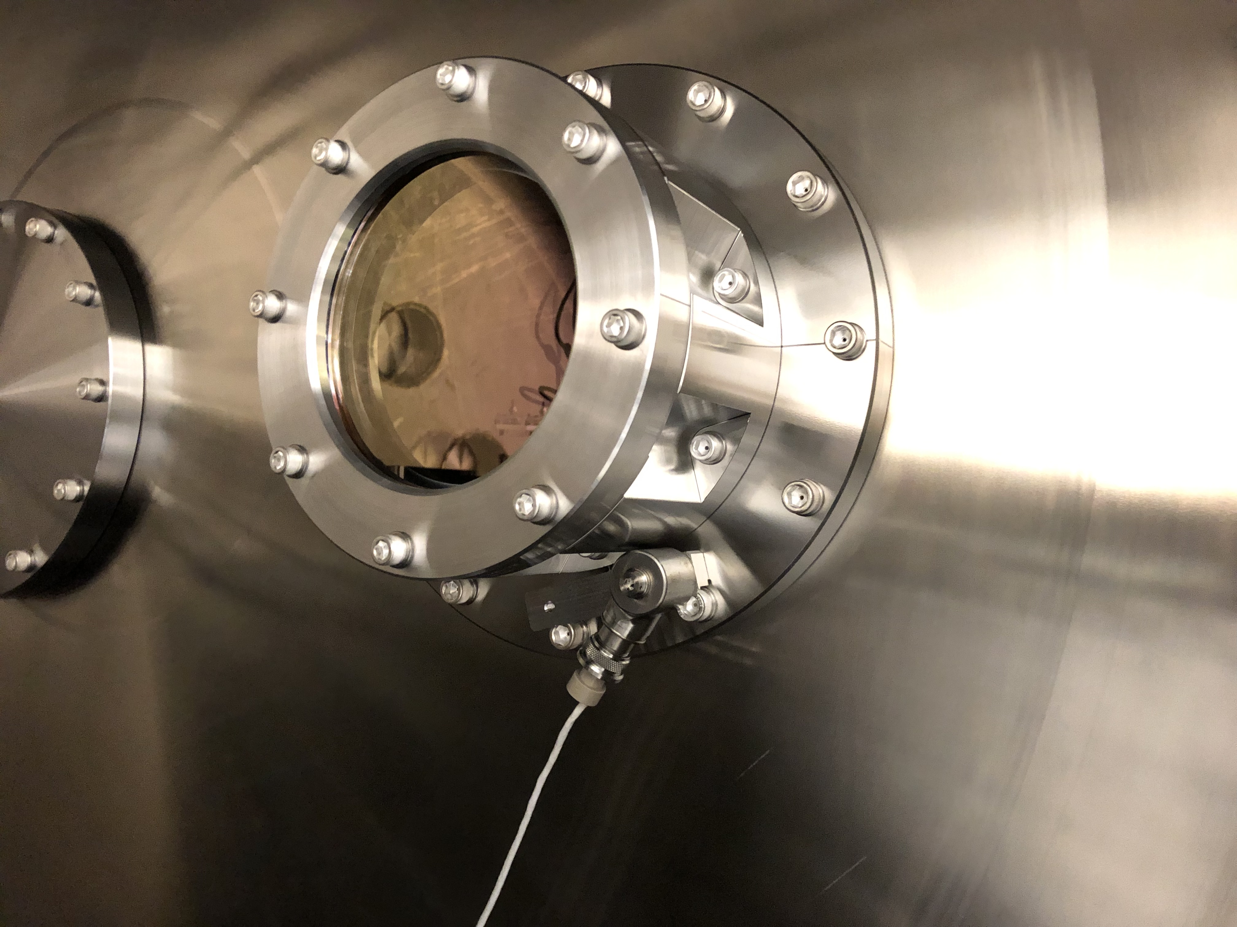
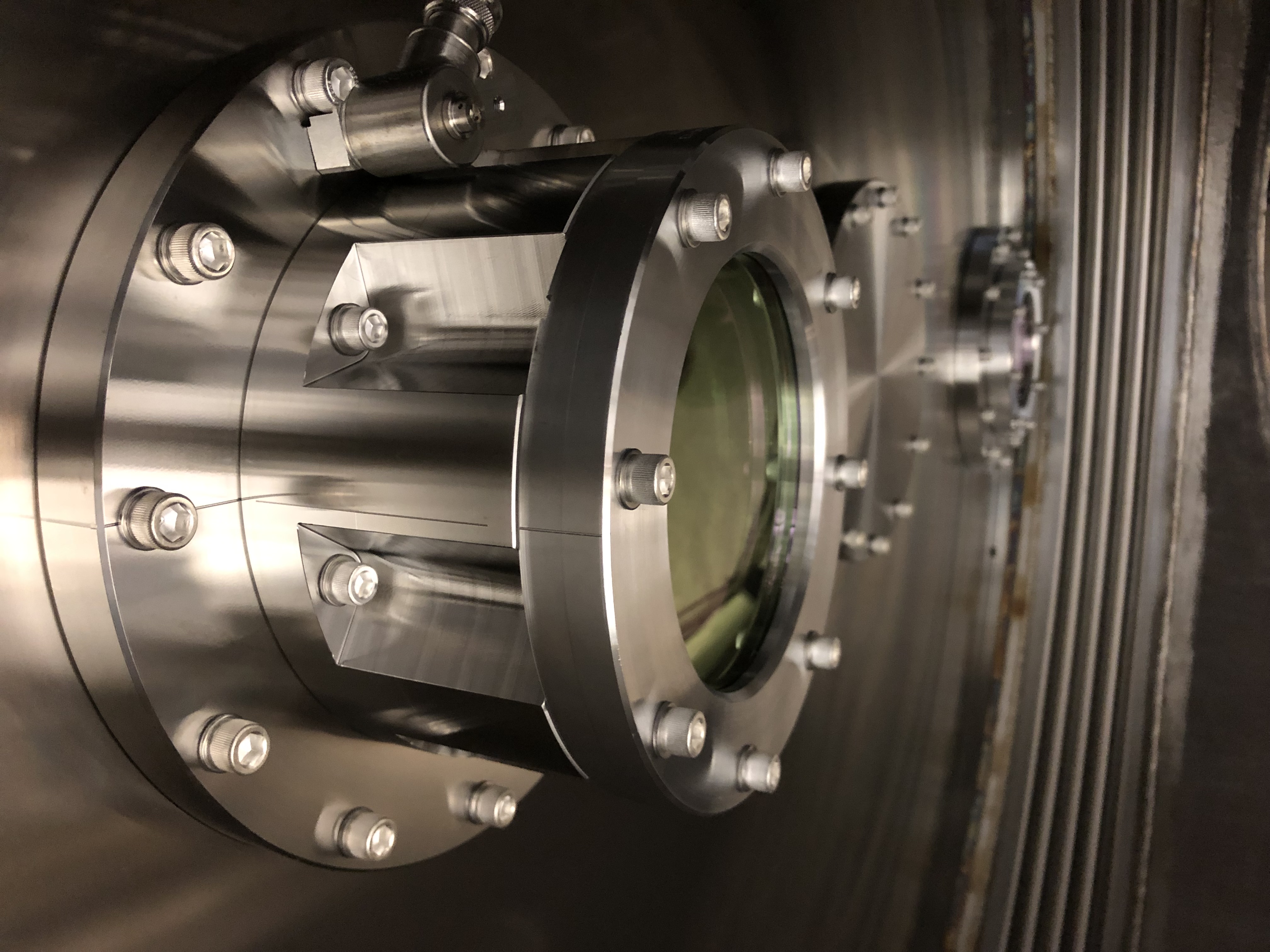
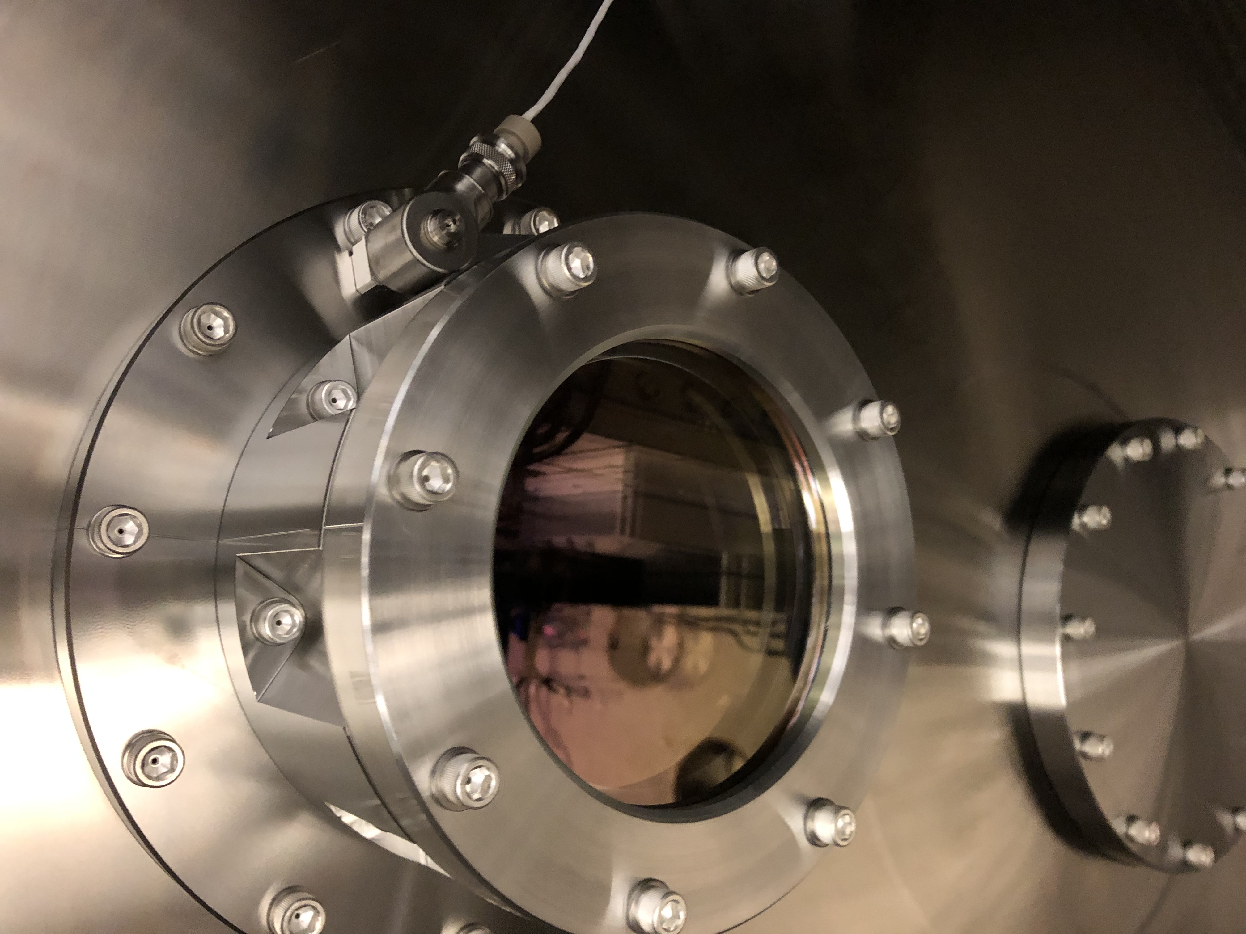
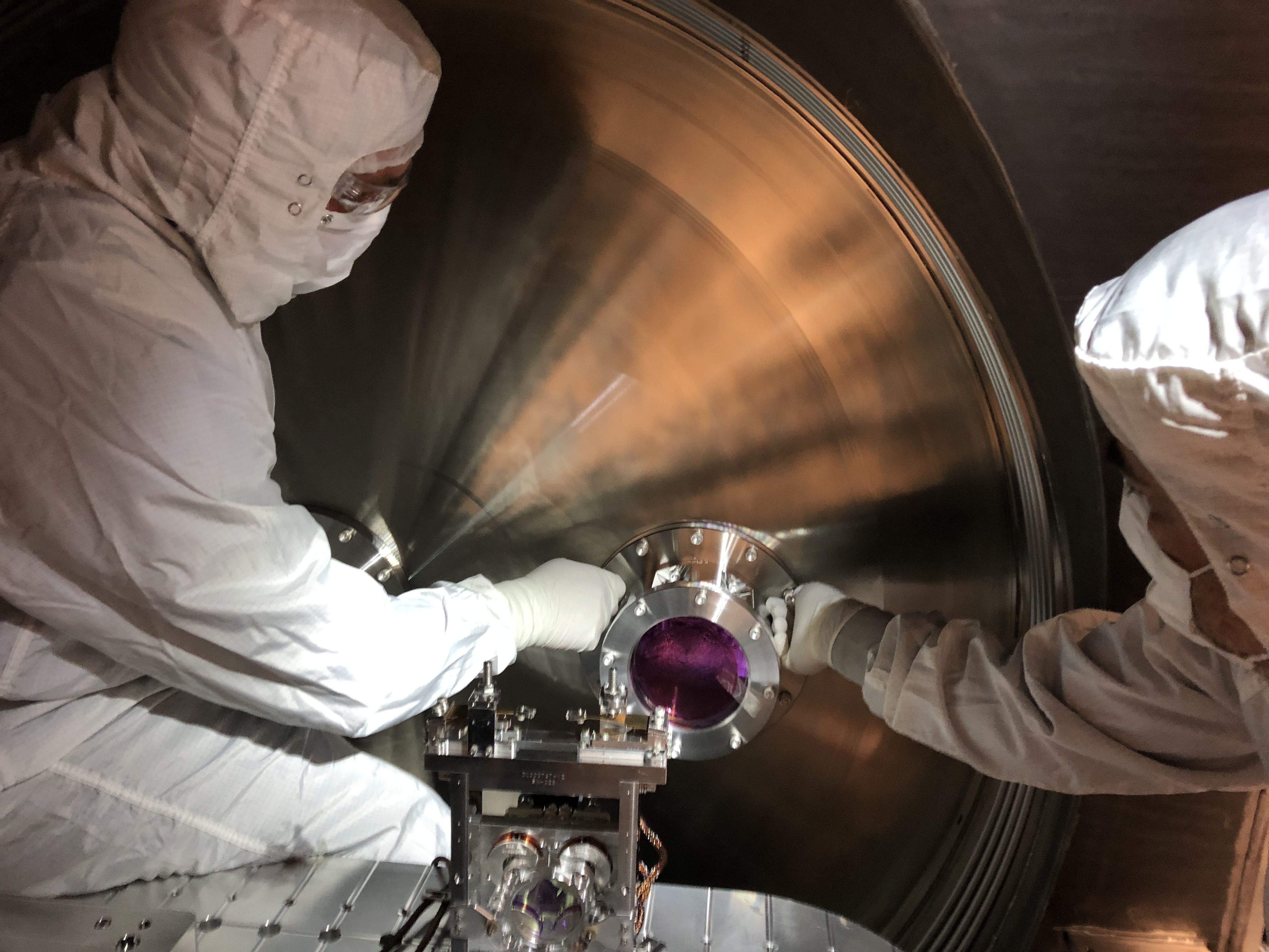
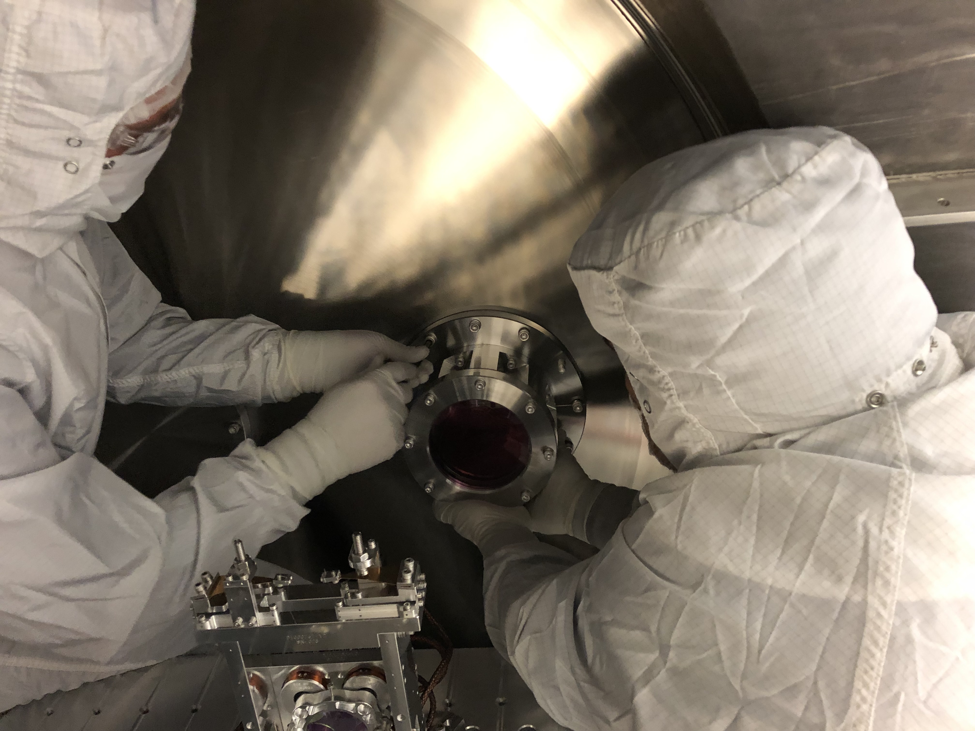
On Monday, old HAM6 OMC path septum window was uninstalled. We measured the wedge angle of that window using a laser pointer in the optics lab.
See attached for the setup. We used an eye safe lasr pointer that passed Peter King's inspection in the optics lab. We were clearly able to see the direct transmission and the first ghost beam, so we just measured the distance between these two beams at two different locations, and derived the relative angle between these two beams, from which we calculated the wedge angle.
The result is w=0.745+-0.022 deg.
See the attached comments for the details of the measurement and the calculation.
The spec is 0.75+-0.02 deg (D1101005) so this seems to be as per spec after all, despite that in the past we believed this to be more like 0.9 deg. (See the history comment attached to this one.)
Oh, and we confirmed that the mark on the flange was on the thickest side, as per the drawings D1101092 and D1101005.
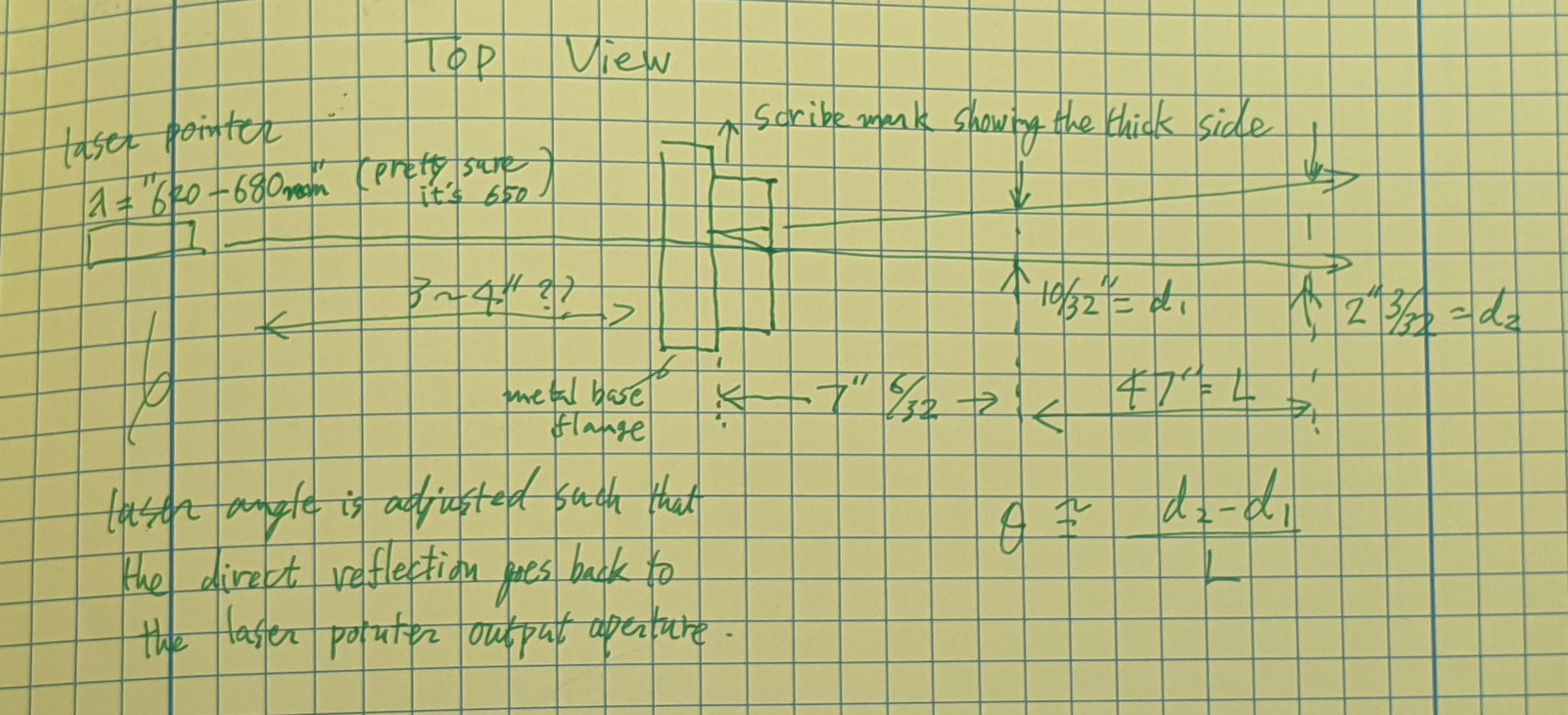
Setup, Measurement and Calculation details.
The incident angle on the first surface of the viewport was adjusted so the return beam goes back into the laser output aperture. I clain the incident angle to be 0+-10mrad, which hardly affects the result in any meaningful way.
The angle between the straight shot beam and the first ghost beam, theta, was measured using the distance between two beams measured at two different locations. Distance measurement was done using clean metal ruler with 1/64" gradation, and I claim that the maximum error that was possibly made for each measurement was 1/32".
Distance between two beams at the first location is
d1=10/32 +- 1/32 inches.
At the second location it is
d2=(2+3/32)+-1/32 inches.
Distance between the first and the second location L was
L=47+-1/32".
After combining errors, the angle between two beams is
theta~(d2-d1)/L=3.79E-2*(1+-0.03).
Taking only the first order of the wedge angle w, the angle between these two beams is very well approximated by 2*n*w where n is the refractive index (n=1.4566+-0.0008 for fused silica, lambda=650+-30nm). Second order error of w as well as the error for n are both much smaller than the 3% overall error in the angle measurement. Therefore
w=theta/2/n = 1.30E-3*(1+-0.03) rad = 0.745 +- 0.022 deg
Nominal wedge = 0.75 deg.
Aug. 2014: Koji used a laser pointer and estimated it to be w~0.89 degrees (alog 13375), and updated the number to 0.91 deg later. This seemed to make sense (e.g. look at alog 13477).
Nov. 2017: When we rotated the window by 180 degrees, the beam position on OM1 changed by 23mm over the distance of 1930mm (alog 39504).
Thus the deflection by the septum window is 23/1930/2~6.0mrad=(n-1)w where n is the refractive index and w is the wedge.
Using n=1.4496 for fused silica at 1064nm, we obtain w~13.3mrad=0.765deg. Suddenly it looks closer to nominal.
Today: Using laser pointer in the lab, w=0.745+-0.022 deg.
Just to make sure, the one we measured is this one
| ASSY-D1101092-3 | HQ Wedged 6 in Septum VP | |
| 2-253V75--BULK-C30Q002 | Dupont O-Ring #AS568-253 Viton 75, V75 FKM, Inside Diameter 5.359", Cross Section 0.139" | |
| D1003207-V1-00-C6Q002 | High quality, 6in Viewport, Viewport Spacer | |
| D1101005-V1-12KWZ-S5-1363-S5-1364-0015 | aLIGO, high quality, .75 deg wedged, 6" Viewport, AR-1064 nm Optic | |
| D1101115-V5-00-0007 | High Quality, 6" Viewport CLAMP, wedged | |
| D1101117-V3-00-0006 | aLIGO Septum Viewport FLANGE |
listed in alog 52377.
The new one that was installed on Monday, i.e.
| ASSY-D1900198-001 | LHO Yawed, Septum Viewport Assy | |
| D070082-V1-00-0006 | ELI Septum Window | |
| D1101117-V3-00-0022 | aLIGO, Septum Viewport Flange | |
| D1900240-V3-00-0001 | aLIGO, VE, HIGH QUALITY VP, WEDGE CLAMP | |
| D1900327-V1-00-0002 | aLIGO, VE, HIGH QUALITY VP ASSY., YAW ADAPTER |
has a wedge angle of 0.727 degrees according to Alena. That one was not obtained by beam angle but by mechanically measuring the thickness of the arrowed edge of the window (thickest) and the edge opposite to that (thinnest).
{Chub, Jordan}
Removed all but four bolts from 84" doors on HAM 11, 12 in H2 volume, in preparation for door removal. Purge air is flowing through the cracks.
{Chub, Jordan}
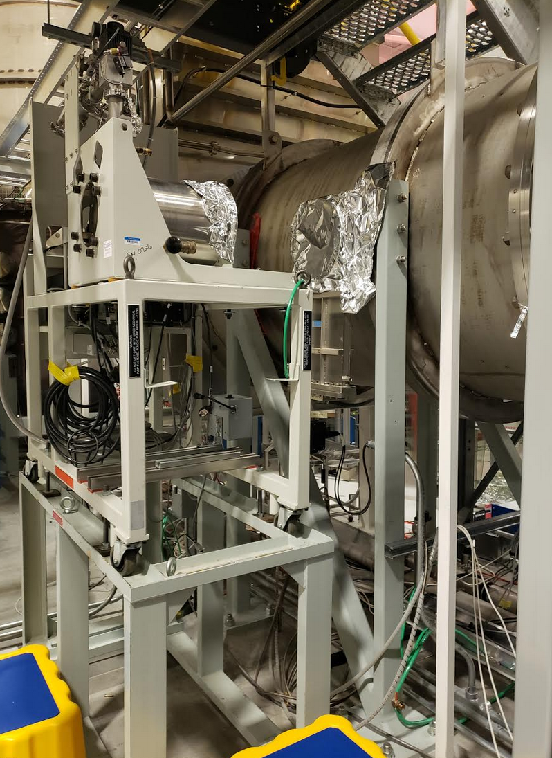
H2 VE is slowly fading. Chub and Jordan decoupled the turbo station near GV4 and removed its large bellows, six way cross, and other components to make it ready to pick with crane after the H2/biergarten portion mezzanine is removed.
Sheila, Nutsinee
To prep for tomorrow beam check we made sure we could lock OPO on double resonance and see the bright seed beam transmitted onto the SQZT6. We aligned the VOPO platform and ZM1, cranked up OPO gain to 15dB (was -17) and reduced the pump light trigger level. All the working value for OPO in-air lock is now in guardian, simply request LOCKED_SEED_HIGH on the SQZ_OPO guardian when we are ready to go tomorrow.
Chandra, Kyle, Dave:
After the MX gatevalves were closed this morning, the pressure in the X1 beam tube (Corner Station to MX) has been steadily rising as anticipated. The MX end exceeded its alarm point of 5.0e-09Torr several hours ago followed by the CS end an hour later.
Chandra has requested that the alarm level for these two gauge readings be increased to 1.0e-08Torr. I have made this change and restarted the alarm system
-<Channel name="H0:VAC-LX_X4_PT144B_PRESS_TORR" low="1.0e-10" high="5.0e-09" description="VE gauge, LX X1-beamtube, CC">
+<Channel name="H0:VAC-LX_X4_PT144B_PRESS_TORR" low="1.0e-10" high="1.0e-08" description="VE gauge, LX X1-beamtube, CC">
-<Channel name="H0:VAC-MX_X1_PT343B_PRESS_TORR" low="1.0e-10" high="5.0e-09" description="VE gauge, MX X1-beamtube, CC">
+<Channel name="H0:VAC-MX_X1_PT343B_PRESS_TORR" low="1.0e-10" high="1.0e-08" description="VE gauge, MX X1-beamtube, CC">
Chandra also requested that the alarm bypass on HAM6 be extended through to the end of next week
Bypass will expire:
Fri Oct 18 15:26:34 PDT 2019
For channel(s):
H0:VAC-LX_Y0_PT110_MOD1_PRESS_TORR
Looks like we've exceeded the 1e-8 Torr setpoint on PT343. Tomorrow we will raise setpoint to 2e-8 Torr.
PT343B alarm level raised to 2.0e-08Torr
Daniel, Nutsinee
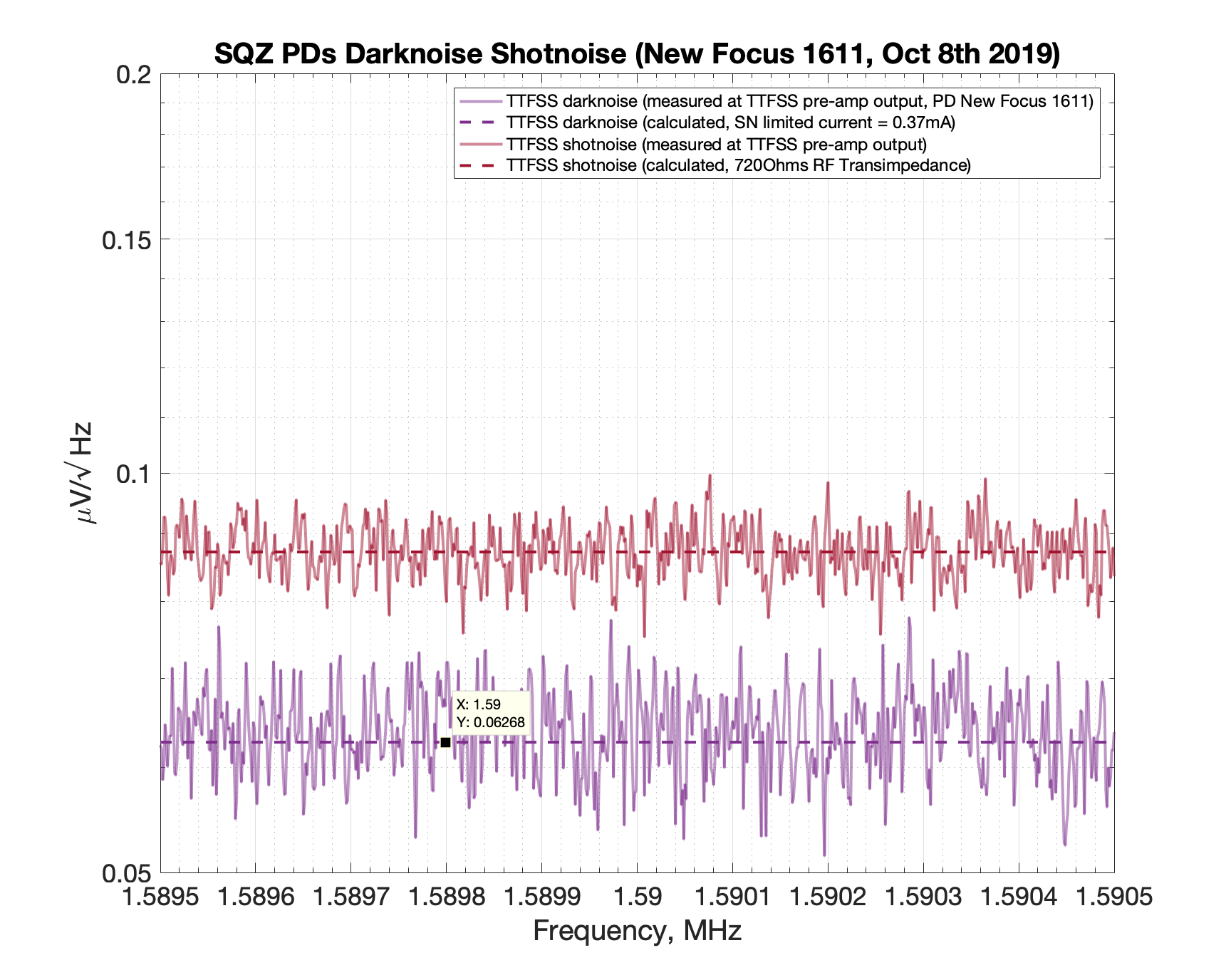
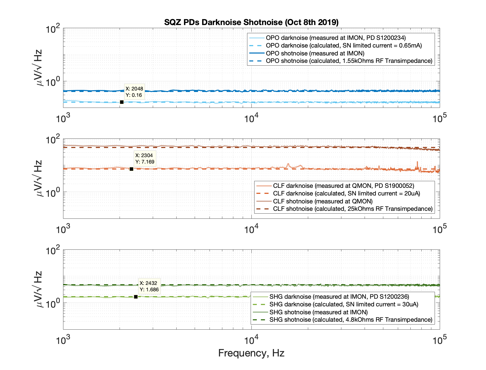
Yesterday we did a series of lightbulb measurement with several squeezer diodes used in OPO, CLF, SHG, and TTFSS loop. The diodes used are as follow:
| SYS | Diode SN | DC transimpedance | RF transimpedance (measured) |
| SHG |
BBPD S1200236 |
20kOhms | 4.8kOhms |
| OPO |
BBPD S1200234 |
2kOhms | 1.55kOhms |
| CLF |
S1900052 |
10kHms | 25kOHms |
| TTFSS | New Focus 1611 | 10kOhms | 720Ohms |
SHG diode has an RF amplifier ZFL-500LN+ (27dB gain) attached and gain a factor of 10 from the mad box gain switch.
CLF diode also has ZFL-500LN+ attached. This is the modified diode from alog47222
The SHG, OPO, and CLF diode spectrum was measured at the IMON (QMON for CLF) output. The IQ demod board gain of 5 has been included. The RF sideband folding factor of sqrt(2) has been included in OPO calculation only (high modulation depth for 80MHz sidebands).
TTFSS New Focus 1611 Agilent spectrum came from the output of TTFSS pre-amp board. Using the pre-amp gain of 8 (+18dB) the calculated transimpedance is 720Ohms (D1700324). The spec sheet claims 700Ohms. Not bad. The measurement came in dBm/Hz. I converted dBm to V^2 using:
P(dBm) = 10log10(V^2/(R*p0))
;R = 50Ohms and p0 is a reference power 1mW
Then I sqrt(V^2/Hz) to get V/sqrt(Hz)
Putting everything in one place for a future reference.
TITLE: 10/09 Day Shift: 15:00-23:00 UTC (08:00-16:00 PST), all times posted in UTC
STATE of H1: Planned Engineering
INCOMING OPERATOR: None
SHIFT SUMMARY:
I spelled Ed off at 10am & Patrick came in starting at 11am. Below are activities I noted while I was in the chair.
LOG:
18:15 UTC Karen to end Y then mid Y 18:52 UTC Niko done in optics lab 19:08 UTC Karen leaving mid Y 19:54 UTC Filiberto to end Y and mid Y to terminate cables for fire panels 20:03 UTC Betsy done transitioning LVEA to laser hazard 20:24 UTC Charlie to optics lab, turning on fume hood, measuring particle counts 20:31 UTC Dan to PSL racks to help Georgia 20:40 UTC Corey, Gavin and Philippe to end X, installing magnetic coil 20:40 UTC Charlie back 20:44 UTC Jason to PSL 20:49 UTC Rick and Timesh to end X, NCAL 20:58 UTC Nutsinee to squeezer table 21:09 UTC Richard out of LVEA 21:11 UTC Nutsinee back 21:21 UTC Georgia and Dan back 21:30 UTC Jason back 21:37 UTC Filiberto done, going to join Corey, Gavin and Philippe at end X 22:00 UTC Vlad and Niko to optics lab 22:06 UTC Vlad and Niko out of optics lab
Topped off Crystal Chiller with 125mL. Diode Chiller OK. Filters look fine (mentioned slight yellow tint of Crystal filter to Jeff B & he said it is OK).
TITLE: 10/09 Day Shift: 15:00-23:00 UTC (08:00-16:00 PST), all times posted in UTC
STATE of H1: Planned Engineering
OUTGOING OPERATOR: Patrick
CURRENT ENVIRONMENT:
SEI_CONF state: SC_OFF_NOBRSXY
Wind: 13mph Gusts, 10mph 5min avg
Primary useism: 0.05 μm/s
Secondary useism: 0.21 μm/s
QUICK SUMMARY:
HAM6 standown still in effect - All Day
Proposed to Betsy and Keita the option of leaving the QDP80 roughing pump valved in overnight to gain headway on pump down (pressure currently at 30 Torr at BSC2 and 20 Torr at pump station). We typically don't pump overnight because of potential risk of backstreaming into main volume if a pump + interlocked valve fails. After some thoughtful discussion we decided it is not worth the risk and will resume per standard procedure and rough during "business hours" when a vacuum person is onsite to monitor and react in case of emergency. HAM6 in-chamber activities will be pushed back as a result, but schedule allows for this. QDP80 is valved out for the night.
The good news is when the new roughing pumps are operational, we will have a second interlocked valve for redundant protection in order to pump overnight.
Good call!
Chandra R., Chub, Jordan, Kyle
The XBM Turbo Station is now installed. Chandra, Chub and Jordan had already removed the iLIGO MTP yesterday and positionined the new Turbo Station. Toward the end of the initialial flanging of the new Turbo Station to the 10" gate valve, Chub had percieved a problem with one of the threaded studs. This issue required a deflanging. In fact, one of the threaded blind holes was damaged and had to be partially rethreaded using a tap. Following this repair, we reflanged this joint, powered the control panel and spun up the turbo. Next, the new CFF joints were helium leak tested (helium background/baseline 1.9 x 10⁻⁹ torr*L/sec) and no leaks were found. We are leaving the turbo spinning overnight without water cooling (backed by the LD). As left, the indicated pump temperature was 24C and the electronics 44C.
After running all night without cooling water, the new XBM turbo indicated temperature was 48C and the integrated (on board) electronics was 56C. We plan to routinely run cooling water under nominal conditions in the future but regulate the flow via an inline needle valve.
Happy it is aligned and leak tight!
{Kyle, Chandra}
Leak checked flange of new PT180 gauge with background of 1.5e-9 mbar-L/s at leak detector. Sprayed helium for several minutes; no leaks.
Ground loop checks for SUS HAM6 complete.
Same issues with ZM1 and VOPO as seen in last November's vent, alog 45409.
HAM6:
ZM1 (Cable label SUS_SQZ-20) Pin 2 shorted to ground
VOPO (Cable label SUS_SQZ-2) Pin 13 shorted to ground
List of cables tested:
H1:SUS_10 (OMC), H1:SUS_11 (OMC), H1:ISC_236, H1:ISC_237, H1:ISC_238, H1:SQZ_1, H1:SQZ_2, H1:SQZ_20, H1:SQZ_21, and H1:SQZ_30.
Ground loop checks for ISC HAM6 complete.
Notes on method used for testing cables:
Checked Pin 13 and shield are tied together. Checked that all pins are not tied to chamber GND.
ISC_307 When testing cable disconnect ISC_404 (OMC QPD)
ISC_404 Passed
ISC_409 Pin 13 and shield not connected
ISC_232 Currently not used
ISC_233 Pins 3&4 shorted in-chamber. Pin 4 pulled.
ISC_234 Passed
ISC_235 Currenlty not used
ISC_265 Pins 14 & 15 connected to sheild (DB15 connector at rack)
ISC_266 Pins 14 & 15 connected to sheild (DB15 connector at rack)
ISC_316 Pin 5 not connected (DB9 connector at rack in CER)
ISC_317 Pin 5 not connected (DB9 connector at rack in CER)
alog 42281, alog 41722, and alog 45409 entries describing existing issues.
Tip-Tilt cables ISC_236, ISC_237, and ISC_238 are now in the SUS-R4 rack next to HAM5.
F. Clara, K. Kawabe
C. Gray, G. Moreno, T. Sadecki, B. Weaver
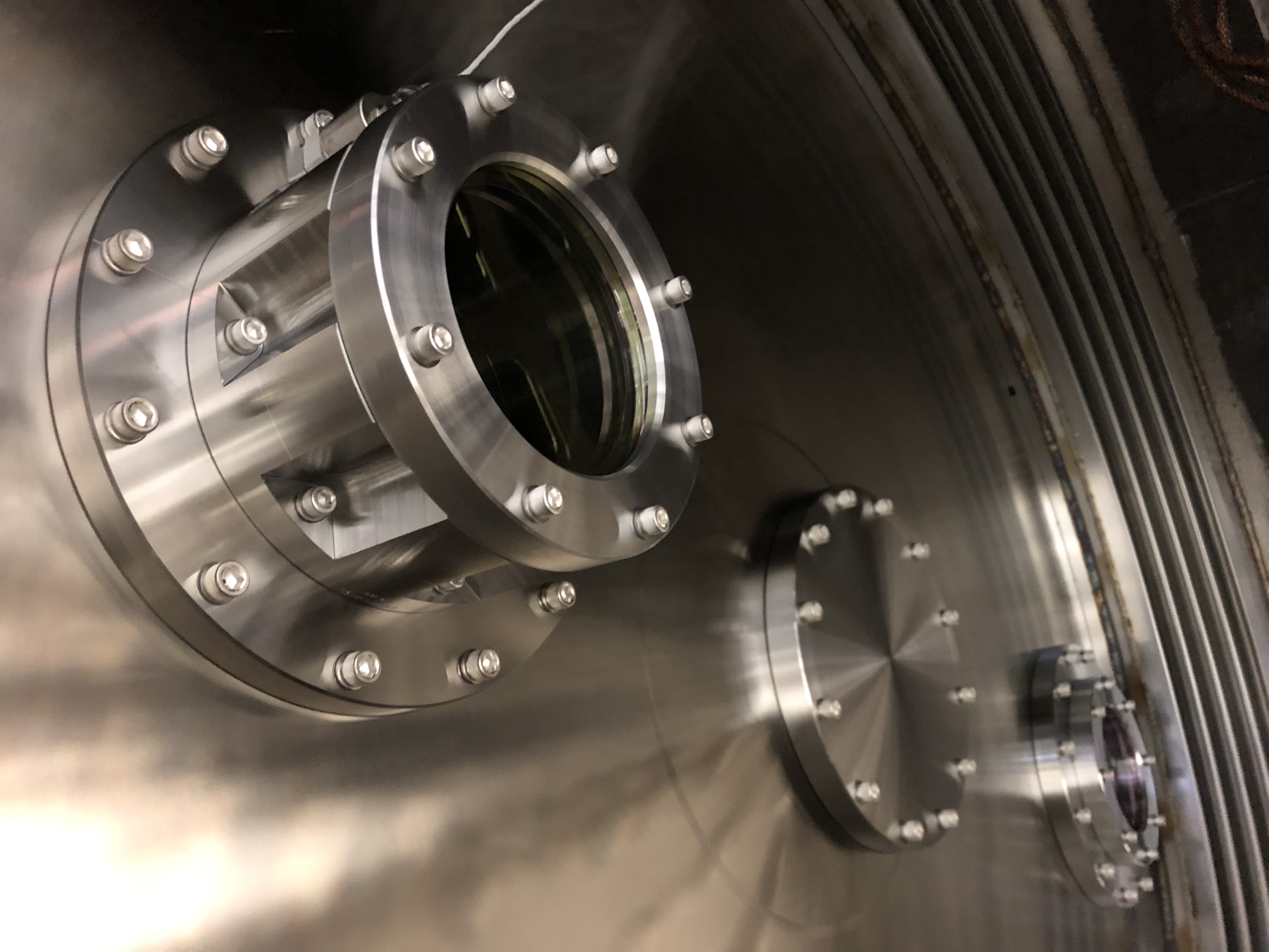
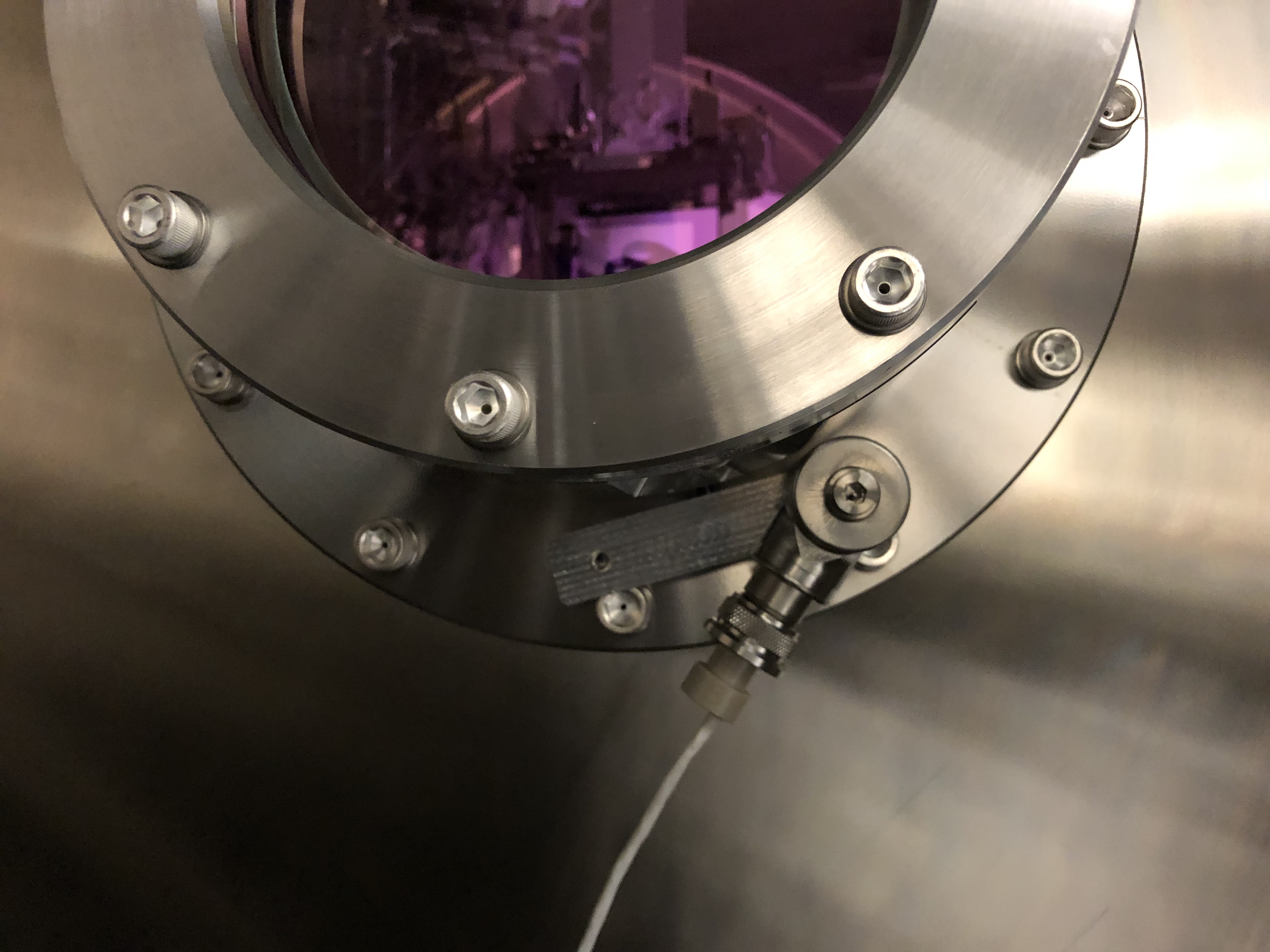
Install of the new yawed septum viewport in HAM 6 went very smoothly today. We utilized 2 of the aligment pins (3/8-16 silver plated screws with the heads lathed down to thread diameter) that Tyler made for us. This made the installation much easier as we had something to take the weight of the 22 kg viewport assembly while installing the mounting flange screws. The septum window accelerometer was reinstalled in the same location it was removed from. First Contact was removed from the inner, HAM 5 side prior to installation, and the outer, HAM 6 side was removed in-chamber after installation and torquing. The center of the viewport aperture was inspected and was deemed free from egregious amounts of particles.
On a related note, this was the first time I had the chance to use the new modular stair system around the HEPIs and can attest that they work much better than the previous iterations of HAM chamber stairs.
Photos to follow.
Attached are photos from new yaw-ed septum viewport install at HAM6 (names of pics gives brief description of image).
Is it in somebody's to-do list to add a notion of the alignment pin fixturing to the documentation? Seems like that fixture should be part of the final drawing package. Let me know if a hand is needed with that.
The "alignment" pins were a last minute tool made to help support the weight of this ~ 50 lb piece of hardware. A design improvement would be to reduce the weight by perhaps making it out of aluminum. It is difficult to get two bodies in the chamber for this maneuver and diverted the time of one of our vacuum engineers a full day.
For the record, this is the AS viewport assembly that was removed:
| ASSY-D1101092-3 | HQ Wedged 6 in Septum VP | |
| 2-253V75--BULK-C30Q002 | Dupont O-Ring #AS568-253 Viton 75, V75 FKM, Inside Diameter 5.359", Cross Section 0.139" | |
| D1003207-V1-00-C6Q002 | High quality, 6in Viewport, Viewport Spacer | |
| D1101005-V1-12KWZ-S5-1363-S5-1364-0015 | aLIGO, high quality, .75 deg wedged, 6" Viewport, AR-1064 nm Optic | |
| D1101115-V5-00-0007 | High Quality, 6" Viewport CLAMP, wedged | |
| D1101117-V3-00-0006 | aLIGO Septum Viewport FLANGE |
And this is the viewport assembly that was installed earlier this week:
| ASSY-D1900198-001 | LHO Yawed, Septum Viewport Assy | |
| D070082-V1-00-0006 | ELI Septum Window | |
| D1101117-V3-00-0022 | aLIGO, Septum Viewport Flange | |
| D1900240-V3-00-0001 | aLIGO, VE, HIGH QUALITY VP, WEDGE CLAMP | |
| D1900327-V1-00-0002 | aLIGO, VE, HIGH QUALITY VP ASSY., YAW ADAPTER |