Chandra R., Gerardo M., Kyle R.
Today we demonstrated the operability of the iLIGO XBM MTP/QDP80 pump pair as connected via the newly installed signal cable. This new cable is part of the upcoming pump upgrade and is not intended to be compatible with the existing iLIGO MTP/QDP80 pumps. As such, temporary "pigtail" cable adapters had to be utilized. Thus, this is a transitional pump-cable-pump configuration. It will be used during the pump/vent cycles scheduled for October and we needed to test the setup ahead of time.
We also temporarily moved the new, to-be-installed, Vertex Turbo Station into the LVEA in order to test if a 2nd, unique, pump-cable-pump combination would be useable in October. In this configuration, the new Pfeiffer Turbo Station is connected to the iLIGO Edwards QDP80 pump via the new signal cable using unique cable adapters (these adapters differ from the above mentioned). For this application, the QDP80 is STARTED/STOPPED locally at the QDP80 with the Pfeiffer Turbo Station only utilizing the QDP80 "PUMP RUNNING" signal during normal turbo operation. The absence of this signal will prevent the Turbo Station's "SAFETY" valve from opening or, cause it to close had it been opened before the loss of signal. Working in conjunction with foreline pressure setpoints this will provide the required "two layer protection" for unattended pumping in October.
The Kobelco vent/purge supply was ran for a few hours without incident - again as preperation for October activites.
The vent/purge supply was also ran at the X-mid. Measured dew point was found to be -41C - Preparation for 10" gate valve replacement in October.
TITLE: 09/17 Eve Shift: 23:00-07:00 UTC (16:00-00:00 PST), all times posted in UTC
STATE of H1: Observing at 112Mpc
OUTGOING OPERATOR: Patrick
CURRENT ENVIRONMENT:
SEI_CONF state: WINDY
Wind: 25mph Gusts, 23mph 5min avg
Primary useism: 0.05 μm/s
Secondary useism: 0.23 μm/s
QUICK SUMMARY:
TITLE: 09/17 Day Shift 15:00 – 23:00 (08:00-16:00), all times posted in UTC
STATE of H1: Observing
INCOMING OPERATOR: Ed
SHIFT SUMMARY: Not too invasive maintenance, ended around 12:30. Went into Observing at 2:00. Wind is high, but we're still locked locked at ~114 Mpc.
LOG:
15:00 (08:00) Start of shift
15:00 (08:00) Kyle to LVEA -- turn on Kobelco pump
15:01 (08:01) Hugh to LVEA -- material organization
15:13 (08:13) Dan to LVEA -- test wifi
15:20 (08:20) Bubba, guest to LVEA -- look at cranes
15:27 (08:27) Richard back from EX
15:28 (08:28) Richard to LVEA -- join tour group
15:35 (08:35) Hugh back from LVEA
15:35 (08:35) Gerardo to LVEA -- check with Kyle
15:47 (08:47) Hugh to EX -- pull down wind fence auxiliary sensors
15:48 (08:48) Matt to LVEA -- mount accelerometer outside HAM3
15:49 (08:49) Betsy to LVEA -- find tour group
15:54 (08:54) Gerardo to back from LVEA
15:54 (08:54) Gerardo to MX -- turn on purge air
15:58 (08:58) Jeff Jones, visitor to EX, EY, roof for ecological survey
16:03 (09:03) Marc, Adrian to LVEA -- catch up with touring group
16:10 (09:10) Chandra to LVEA -- meet with touring group
16:14 (09:14) TJ to LVEA -- get verbal, key off TCSY laser
16:19 (09:19) Ken to EX -- continue PEM supports installation
16:26 (09:26) Matt out of LVEA
16:28 (09:28) Tyler to LVEA -- find Chandra
16:31 (09:31) Betsy out of LVEA
16:33 (09:33) Karen leaving EY
16:39 (09:39) Chris to LVEA -- set up eye wash signs/do safety checks
16:40 (09:40) Touring group members out of LVEA
16:43 (09:43) Vanessa back from MX
16:43 (09:43) Vanessa to LVEA
16:52 (09:52) Bubba out of LVEA
16:58 (09:58) Marc, Adrian, Gavin to CER
17:00 (10:00) Fil to LVEA -- fiber pulling
17:08 (10:08) Chandra out of LVEA
17:08 (10:08) TJ to LVEA -- TCSY chiller replacement
17:14 (10:14) Jeff to CER -- check on CER work after computer error
17:20 (10:20) Jeff back from LVEA (?)
17:21 (10:21) TJ to LVEA -- turn on CO2Y
17:25 (10:25) TJ back from LVEA
18:00 (11:00) Fil back from LVEA
18:02 (11:02) Hugh back from EX
18:09 (11:09) Jeff Jones, visitor done with survey
18:22 (11:22) Gerardo back from MX
18:23 (11:23) Tyler out of LVEA
18:24 (11:24) Chris out of LVEA
18:24 (11:24) Chris to EX, EY -- put up eye wash signs in VEAs
18:32 (11:32) Chandra to LVEA -- spin down turbo
18:35 (11:35) Rich, Adrian, Daniel, Kara to CER -- look at electronics
18:39 (11:39) Sheila out of Optics Lab
18:44 (11:44) Tyler done with high bay work
18:51 (11:51) Gavin, Marc, Adrian back from CER
18:53 (11:53) Chris back from end stations
18:55 (11:55) Daniel, Kara, Rich out of CER
18:57 (11:57) Ken done with EX work
19:03 (12:03) Fil done at EX, EX swept
19:03 (12:03) Kyle, Chandra out of LVEA -- ToO fan turn off in 1-2 hours
19:18 (12:18) Starting initial alignment
19:48 (12:48) Initial alignment complete, starting re-lock
20:11 (13:11) Lockloss from CARM_TO_TR
20:40 (13:40) Kyle to LVEA -- turn off fan
20:45 (13:45) Chris to halfway to MX -- drop off cable for bee-movers
20:48 (13:48) Kyle out of LVEA
21:00 (14:00) Locked at NLN, accepting sdf changes and going into Observing
21:06 (14:06) Chris back from cable drop-off
23:00 (16:00) End of shift
shifter: Brennan Hughey fellow: Matthew Ball link to full shift report * Fairly quiet week from a data quality perspective. 68.9% observing based on summary pages (reduced by a couple software issues: alogs 51838 and 51883 ) in the vicinity of 110-115 Mpc range. * Front-end calibration improved from Monday September 9th and is in better agreement with GDS, see Jeff Kissel's alog 51819. Detcharians will note that the gray trace on the range plots in the summary plots dropped about 5 Mpc late Monday onwared to be in better agreement with the red GDS trace. * A bad period of scattering occurred 20-22 UTC on Monday September 9th along with glitches above 2 kHz. In terms of environmental noise, this most closely correlates with EY ground motion in the 0.3-1Hz band, which just appears to be wind based on Matthew Ball's investigation. * Rung-up violin mode late Saturday corresponds to visible omicron glitches, which is unusual and seems potentially problematic for long duration burst and possibly other searches. * Hveto results are typical for recent data, the round 1 winner is an LSC channel witnessing persistent low frequency glitching just above 10 Hz (LSC-REFL_A_LF_OUT_DQ,LSC-REFL_A_RF9_Q_ERR_DQ,LSC-PRCL_IN1_DQ), LSC-POP_A_LF is also a significant channel, typically round 2, as a witness of loud glitches and occasionally scattering. * As of September 15th, it has been 75 days since the last significant outbreak of whistles coupling into DARM.
Betsy, Rahul
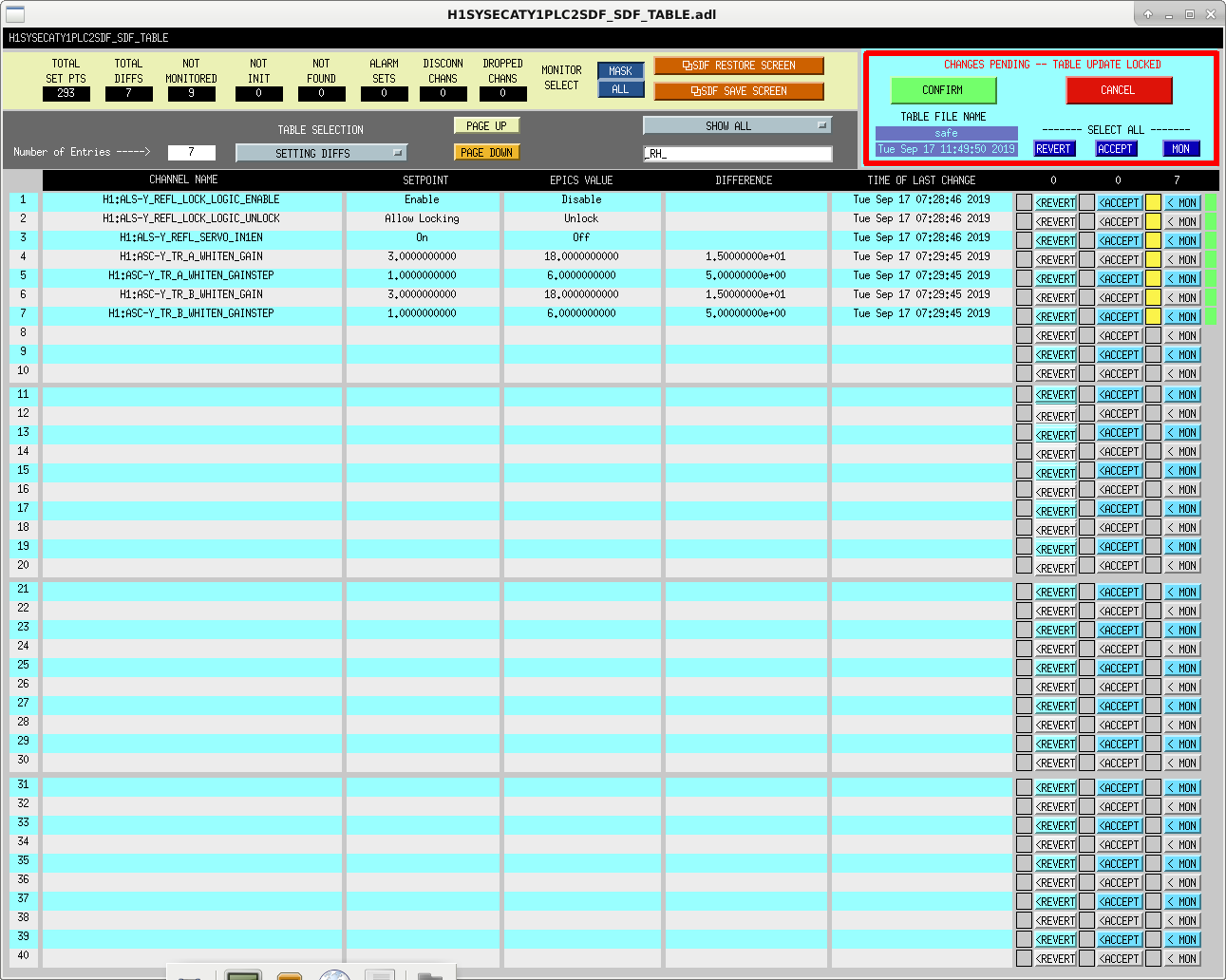
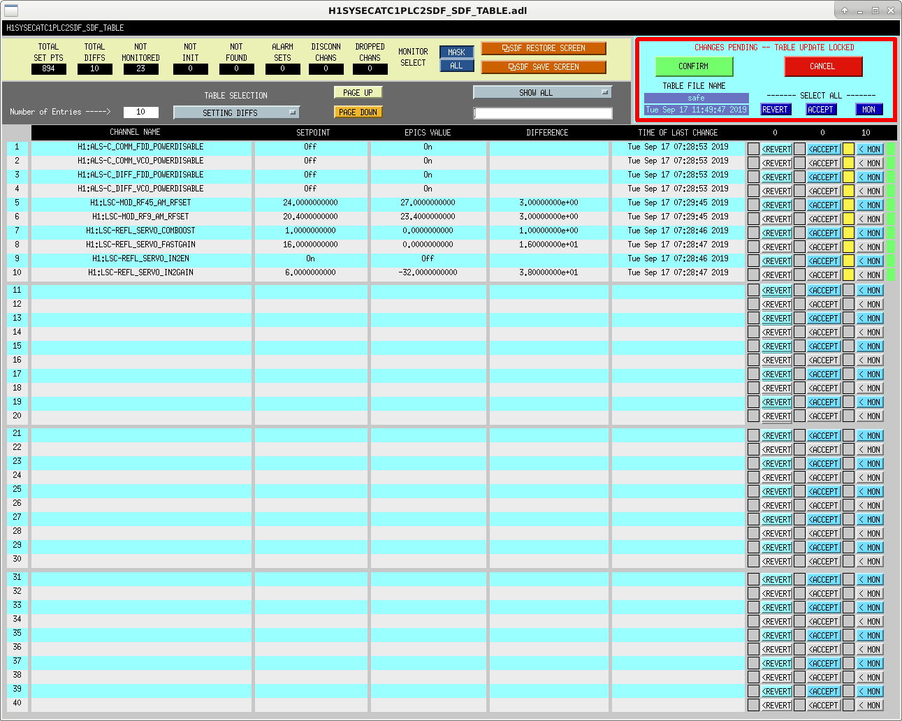
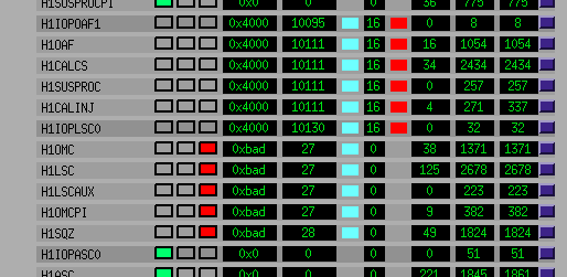
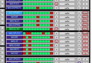
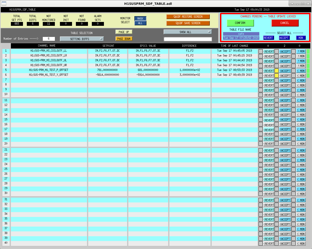
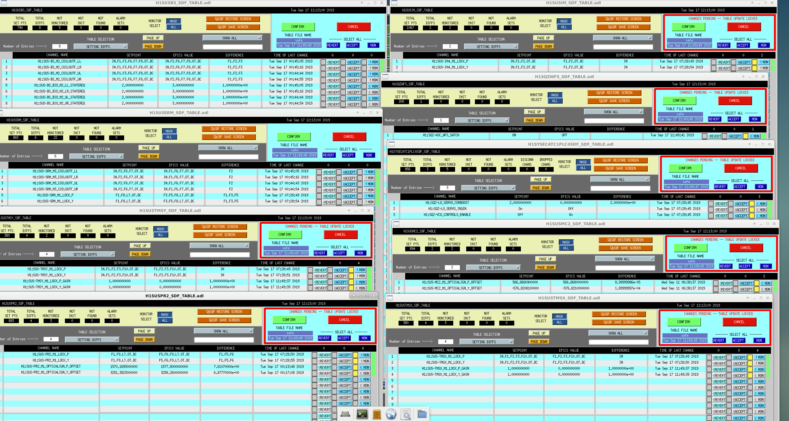
We have unmonitored several of the SDF differences while the IFO was in DOWN state. We took screenshots of them for reference, and is attached below.
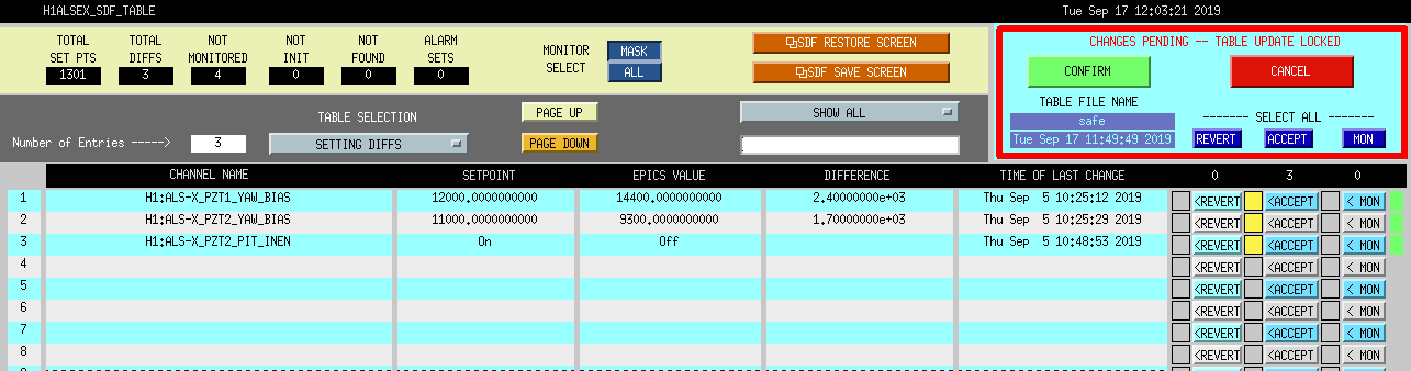
I also accepted a change to ALSEX PZT bias made back on Sept. 5 by Keita and I(alog51751).
EX swept by Fil. K. Roland and C. Soike were the only entry to EY for regular cleaning and installation of eye-wash signs, respectively. They only turned on lights and we confirm they're OFF.
WP8349
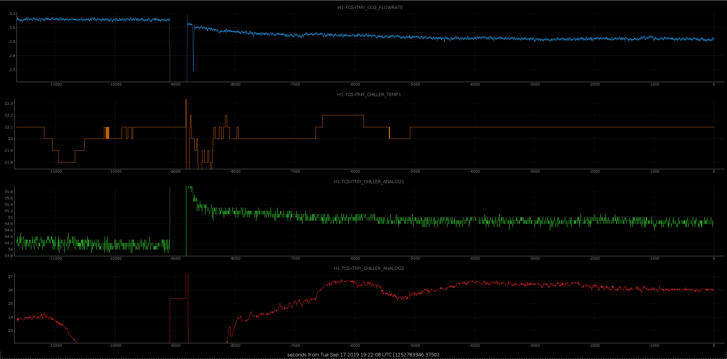
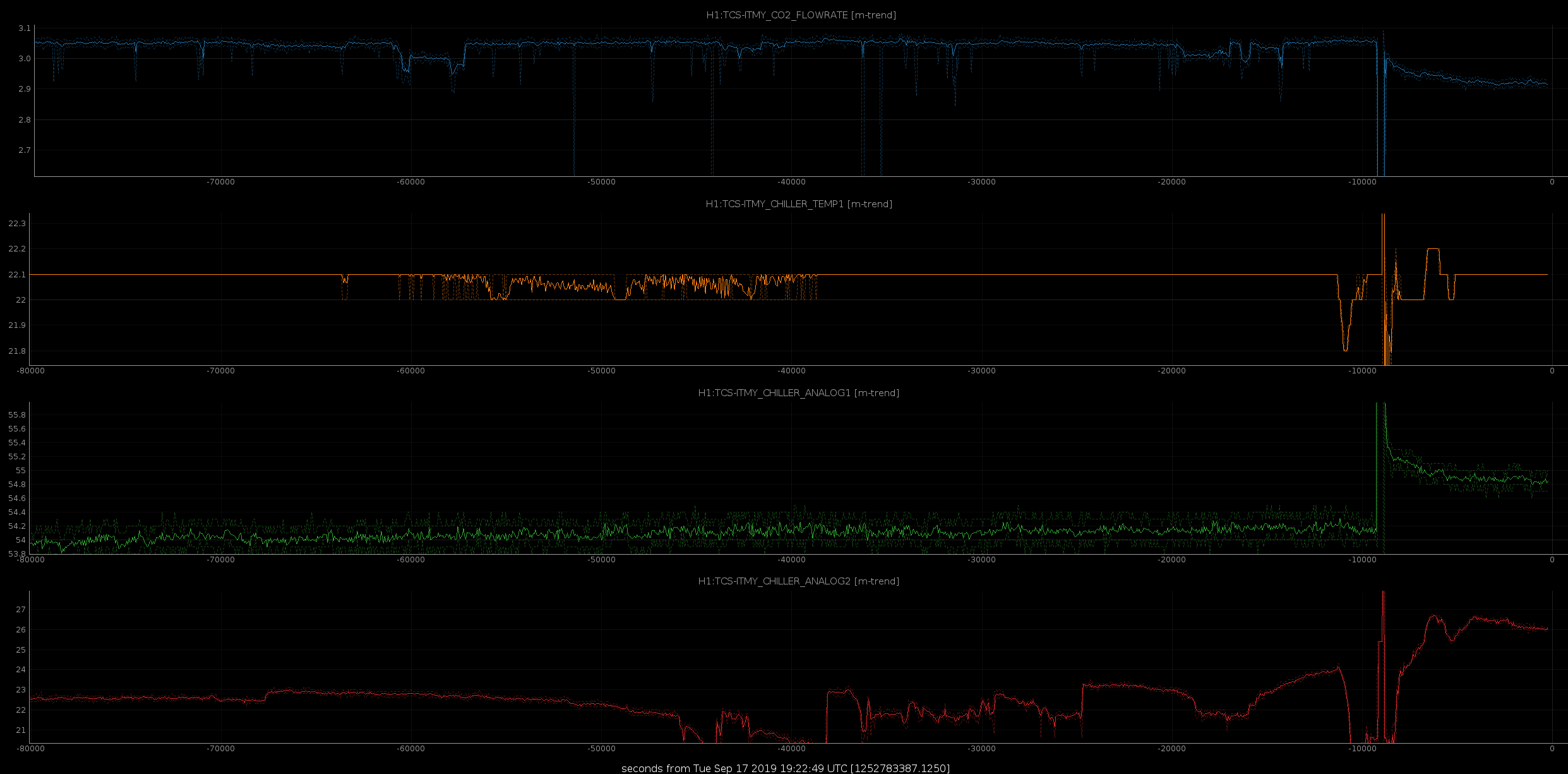
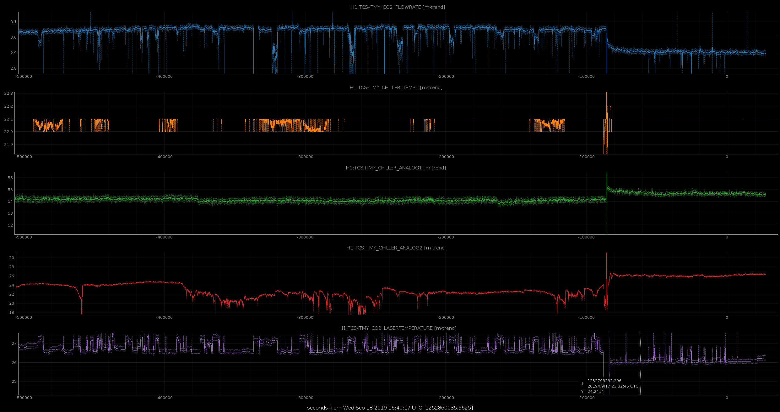
Betsy and I swapped the TCSY chiller with the rebuilt original chiller. This chiller was swapped back in January due to a leaky shaft seal. There was lots of corrosion in the pump, so we got a brand new pump and motor mounted and tested.
The hope with this chiller swap is that this chiller's temperature is a bit more stable and we won't have as many laser relocks that take us briefly out of observing (see alog 50789 for more info).
The laser recovered within an hour as usual, and temperatures and pressures all seem good. For the short time that we have been running with this current chiller, it looks good. Time will tell.
Current chiller: S/N127640801150617
Old chiller: S/N0110193301120813
-----
(Analog_1 is pressure in psi. Analog_2 I believe is actually temperature near or on the laser itself, not pressure as the medm states.)
Attachment 1 - The current chiller stabilizing.
Attachment 2 - One day trend, showing the current values compared to the old chiller.
I tested the transmission of the green feedthrough SN6 we are planning to install in October, following the procedure on page 13-16 of S1800777
I measured 5.7mW out of the fiber laser, 3.8mW out of the first low insertion loss fiber, and 2.8mW out of the 5 meter low insertion loss fiber. I measured 2.19mW of output power, so the transmission of the fiber was 78% in this test, compared to 86% reported in S1800777-v5.
Famis11030
Laser Status:
Front End Power is 32.36W (should be around 30 W)
70W Output Power is 70.7W
Front End Watch is GREEN
70W Watch is GREEN
PMC:
It has been locked 18 days, 23 hr 38 minutes (should be days/weeks)
Reflected power = 10.95Watts
Transmitted power = 53.81Watts
PowerSum = 64.76Watts.
FSS:
It has been locked for 0 days 0 hr and 55 min (should be days/weeks)
TPD[V] = 5.002V (min 0.9V)
ISS:
The diffracted power is around 1.7%
Last saturation event was 0 days 0 hours and 53 minutes ago (should be days/weeks)
Possible Issues: None
Except for #4, H1:PEM-X_FENCE_WIND_SPEED_4_MPS, which is on the roof, all the proto fence sensors have been pulled down to make room for the fence construction.
h1lsc0 (master) glitched, which in turn caused h1oaf1 (slave) to have problems.
I restarted all the models on these systems at 10:35. Jeff investigated if the glitch could be reproduced.
The double-edged sword of cutting-edge electronics science
A. Helmling-Cornell, J. Kissel, M. Pirello, G. Wallace
While Marc, Adrian, and Gavin were out this morning setting up test equipment to continue their study of SQZ phase noise on the 3.125 MHz line, we found ourselves with another LSC front-end crash. Again zooming out there to try to identify what is causing these occasional glitches, they imagined that it might have been coincident with several activities:
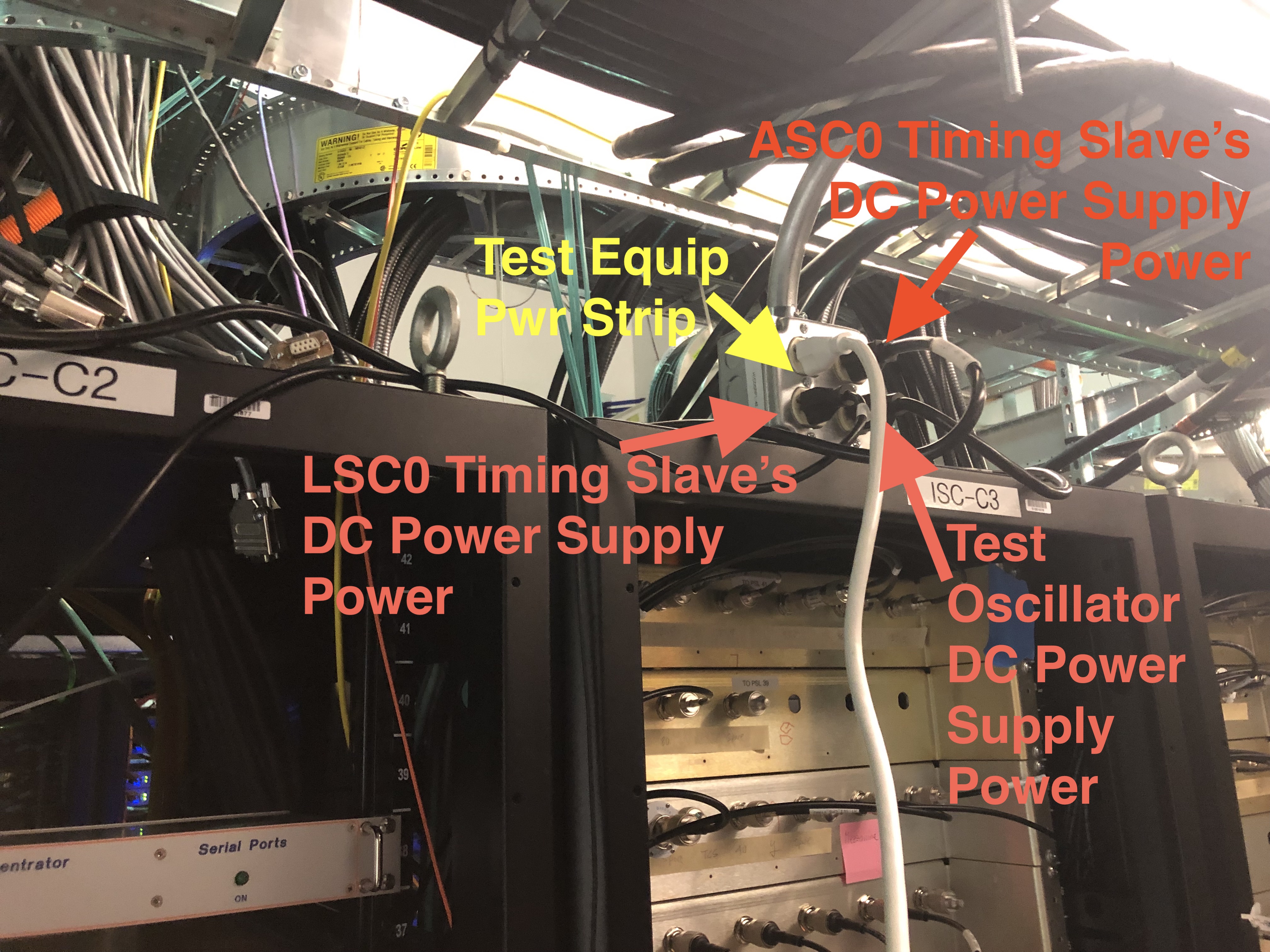
- Plugging in their test equipment (via surge protector) to the 4th, only available, socket of the wall-wort power hub above ISC R3.
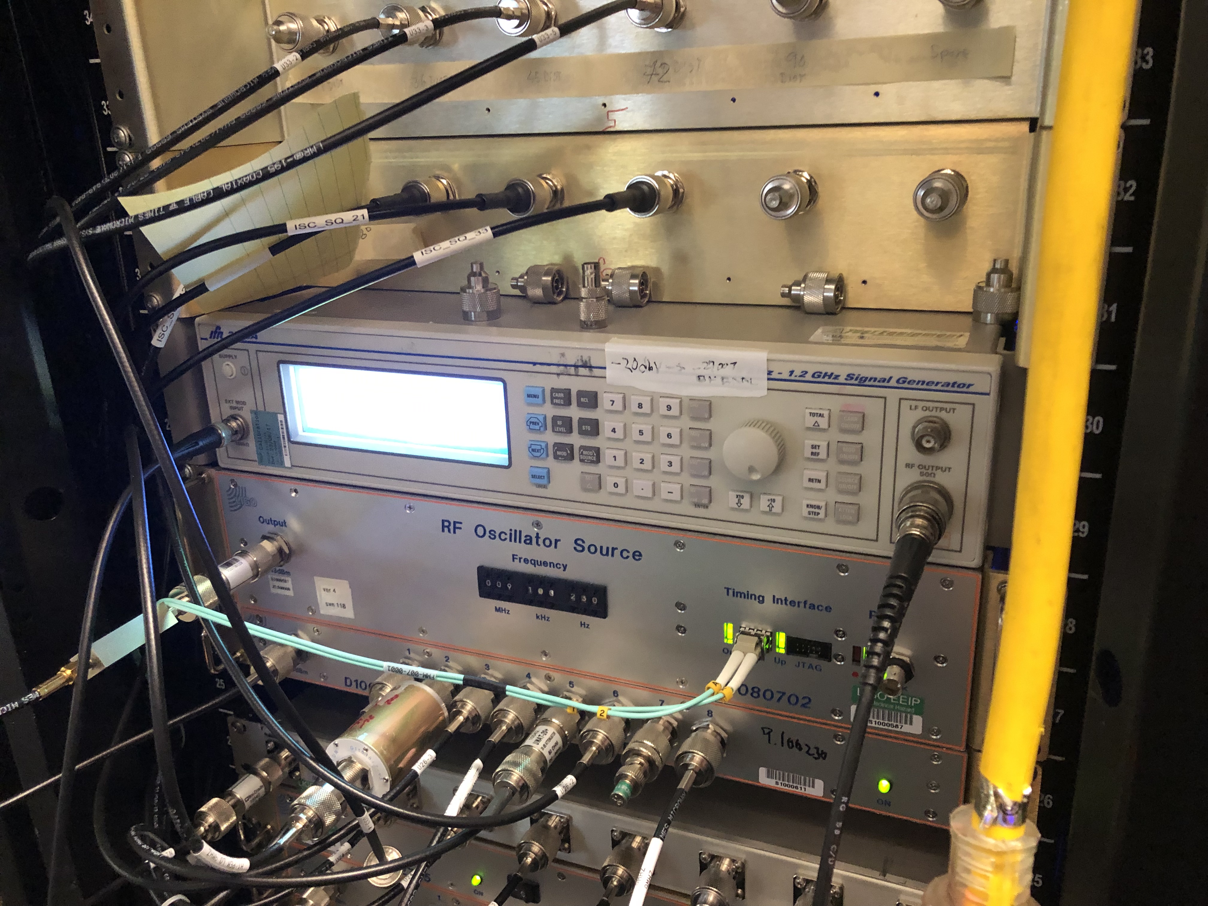
- Turning off the temporary (though permanently mounted) test RF oscillator in ISC R4 (powered via a power strip via the same wall-wort power hub)
- Jostling the timing fibers coming in/out of the timing distribution system
As such, after Dave restored the lsc0 front-end models, we ran through *many* iterations of the same activity, hoping to find *something* the reproducibly crashes the front end.
- With the test equipments' surge protector plugged in to the 4th socket, we turned OFF, then ON the protect ~5 times. No crash.
- With the test equipments' protector in the ON configuration, we installed and pulled out the plug from the 4th socket ~5 times. No crash.
- Turned on / off the surge protect for the test oscillator ~5 times.
- Jostled all of the power plug is in the wall-wort power hub. No crash.
- Gently fussed with all of the timing fibers at the timing distribution ports. No crash.
- Gently fussed with the timing fiber going in to the lsc0 IO chassis. No crash.
- Gently fussed with the DC power cables going in to the lsc0 IO chassis. No crash.
- Connected / disconnected the test equipment from the 3.125 MHz TNC ports under test. No crash.
So we're back to superstition-level "just don't go near anything," but this is just infeasible to follow and should not be the case. Having no better course of action to take, I've taped off the 4th socket with a label that says "DO NOT USE FOR TEST EQUIP."
First attachment shows the wall-wort power hub above ISC R3 before equipment was unplugged.
Second attachment shows the power supplies for the timing slaves for both the ASC and LSC IO chassis on top of ISC R1
Third attachment shows the LSC IO chassis and the temporary power cable leading in to it.
Fourth attachment shows the wall-wort power hub above ISC R3 now in the "DO NOT USE" configuration I left it.
Fifth attachment shows the permanently installed test oscillator in ISC-R1.
This "temporary" configuration of power supplies has been in place since WELL before the start of the run, originally in Sep 2018 -- according to the very terse, and closed FRS ticket about it (see FRS Ticket 11452), and then revisited Mar 2019 (see LHO aLOG 47673) which -- in fact -- glitched the LSC system upon install (see LHO aLOG 47681 and FRS Ticket 12567).
The most recent, last, time such a glitch because "people were near the racks, but no obvious cause" happened was Aug 29 2019 -- see LHO aLOGs 51616 and 51630. Other occurrences will be a challenge to retrace, as these crashes often happen in the middle maintenance day and/or recovery, and in the chaos folks want to just get *something* written down, and that *something* is often inconsistent and terse.
Finally -- this temporary configuration of power supplies for our most sensitive ISC IO chassis timing slaves and fans are *still installed* because we know that new IO chassis are coming in the future, and [as far as I know] don't want to replace them during the run because it's a big operation. I'll confirm this representative parties.
Updated IIET Ticket 11494 to reflect the systemic problem of these temporary power supplies that were installed (maybe pre-O2?) in order to mitigate fan and timing noise.
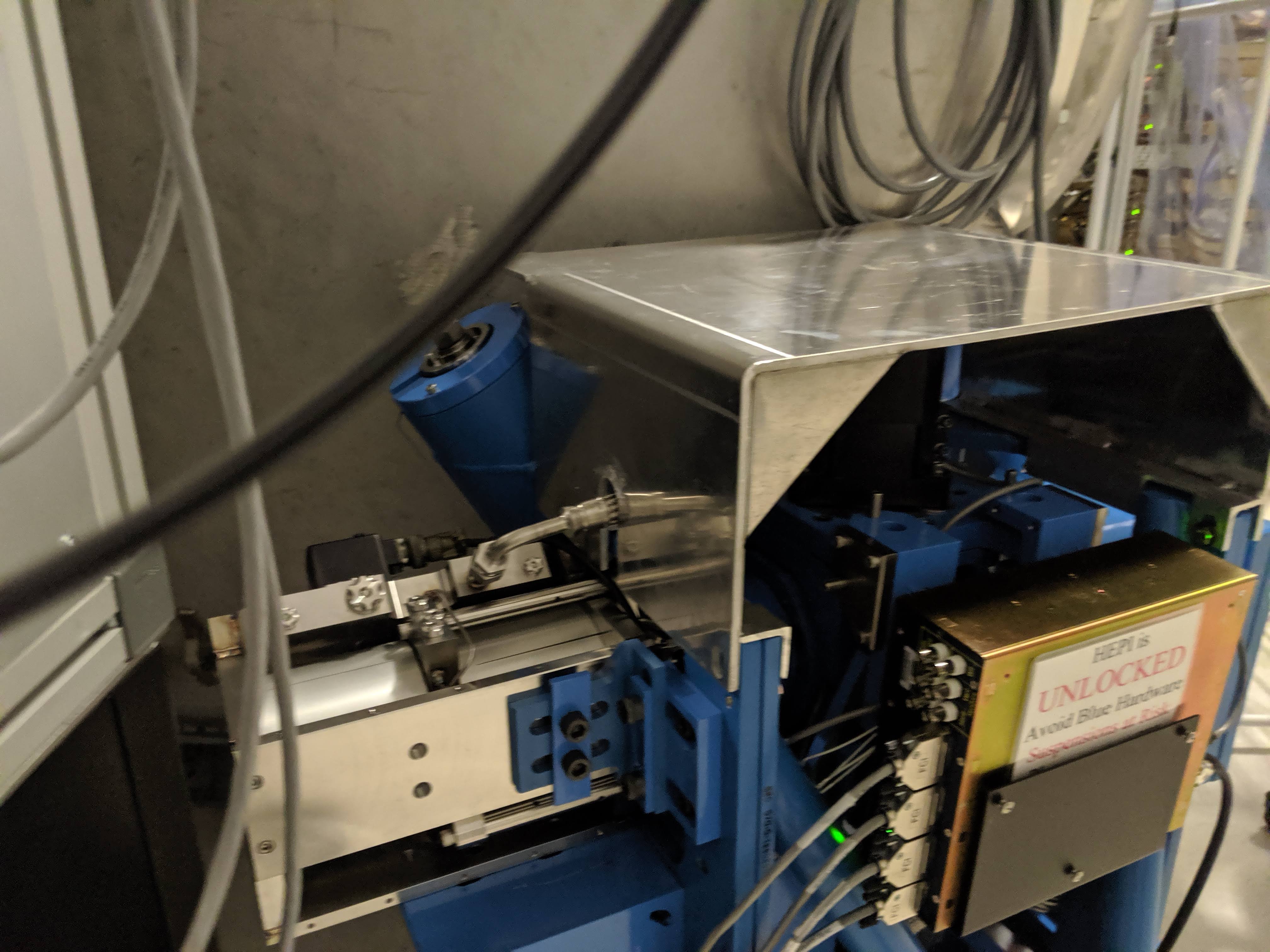
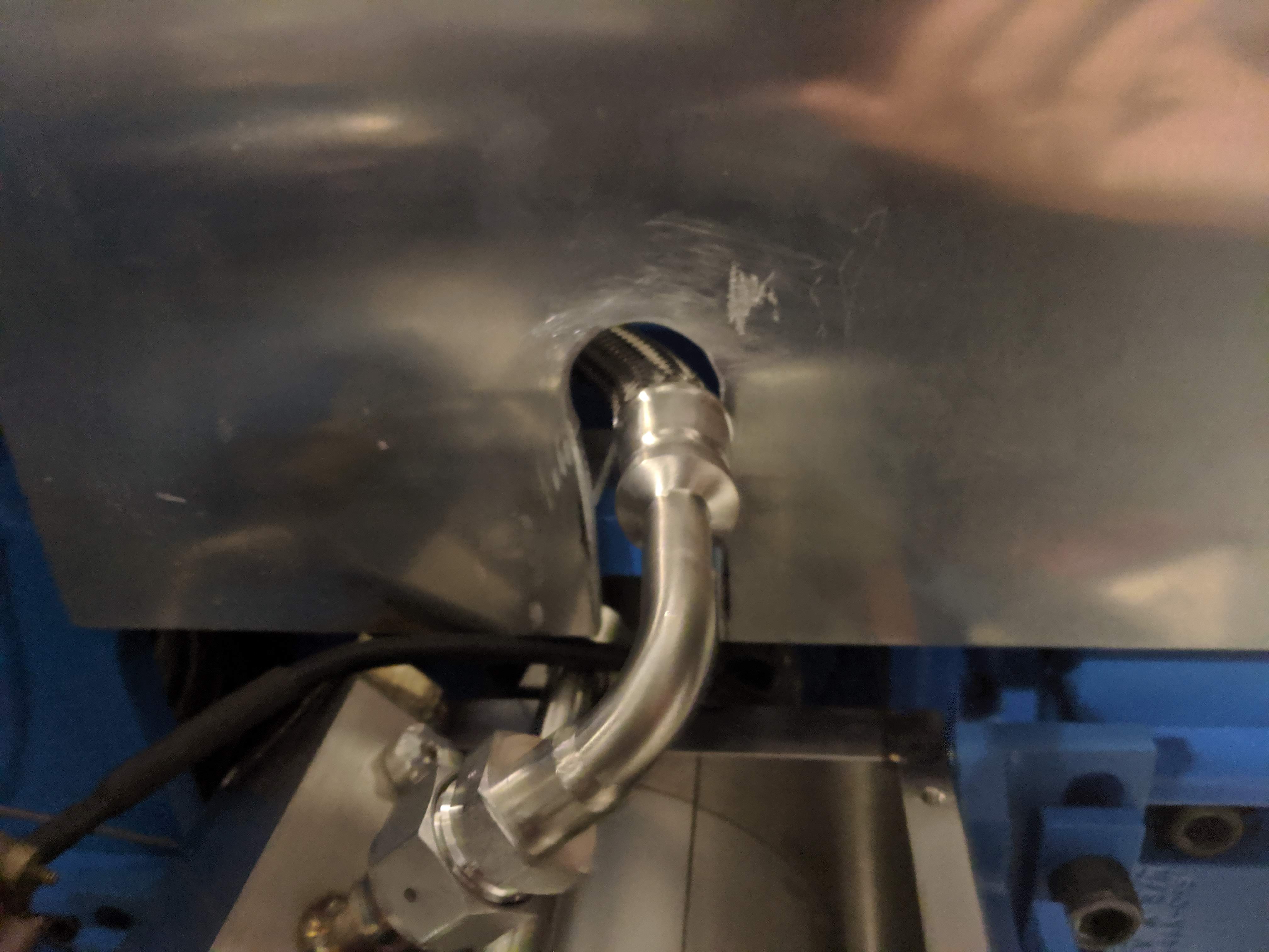
The "new" HEPI work covers fit on the HEPI housings, but because of the way the hoses are run, I think all of them will need to be reworked, or we'll have to re-route some of the hoses on all the housings. Hugh looked first thing and saw that one of the horizontal actuator hydraulic lines interferes with the cover. I took one to the warehouse and notched it, took it back out and installed it on the SE corner of HAM6. Didn't even trip the ISI or HEPI.
First image is the installed cover on the pier, second image is a close-up of the notch around the hose. Hard to see, but I made sure the line isn't touching the cover.
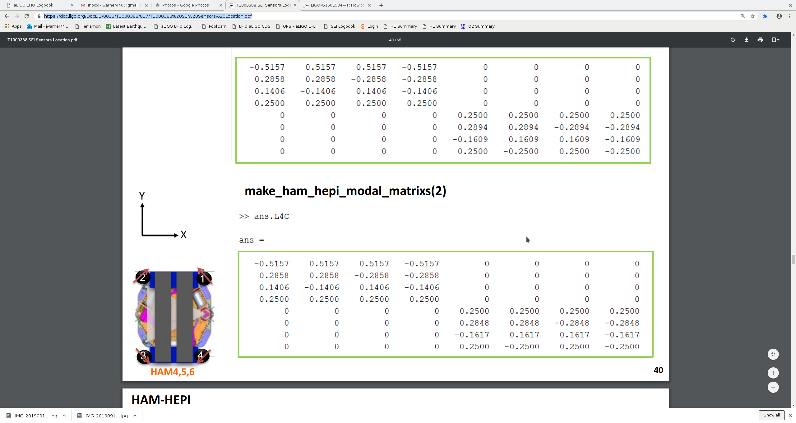
Third plot are asds for all of the HAM6 HEPI L4Cs, for both plots green (H3/V3) are the pier I put the cover on, brown (H4/V4) are the L4Cs on the pier on the opposite end of the blue cross-beam (according to page 40 of T1000388 , fourth image, lower left cartoon). I don't see any worrying differences, but there is a lot going on in the LVEA right now, I'll run another comparison tomorrow for a quiet time overnight.
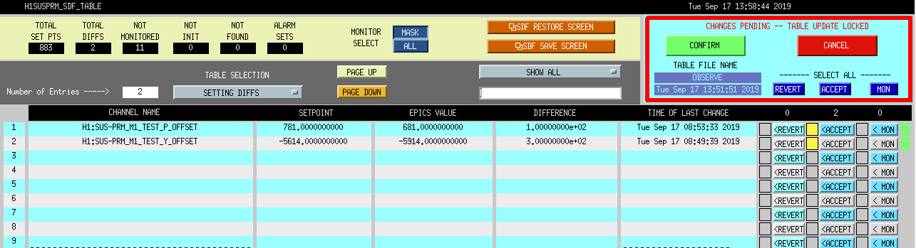
The previous offsets for parking the REFL beam were allowing some of the beam back onto Calcite Wedge 2, as seen in the IO_FI_OUT analog camera. Offsets are H1:SUS-PRM_M1_TEST_P_OFFSET and H1:SUS-PRM_M1_TEST_Y_OFFSET. Pitch offset was+781, now +681, yaw offset was -5614, now -5914. Accepted in SDF.
Accepting sdf's in Observe.
I don't remember of the top of my head what the calibration of these offsets to urad is, but we need to ensure that the reflected beam will still be hitting the dedicated beam dump on top of HAM2 when PRM is misaligned.
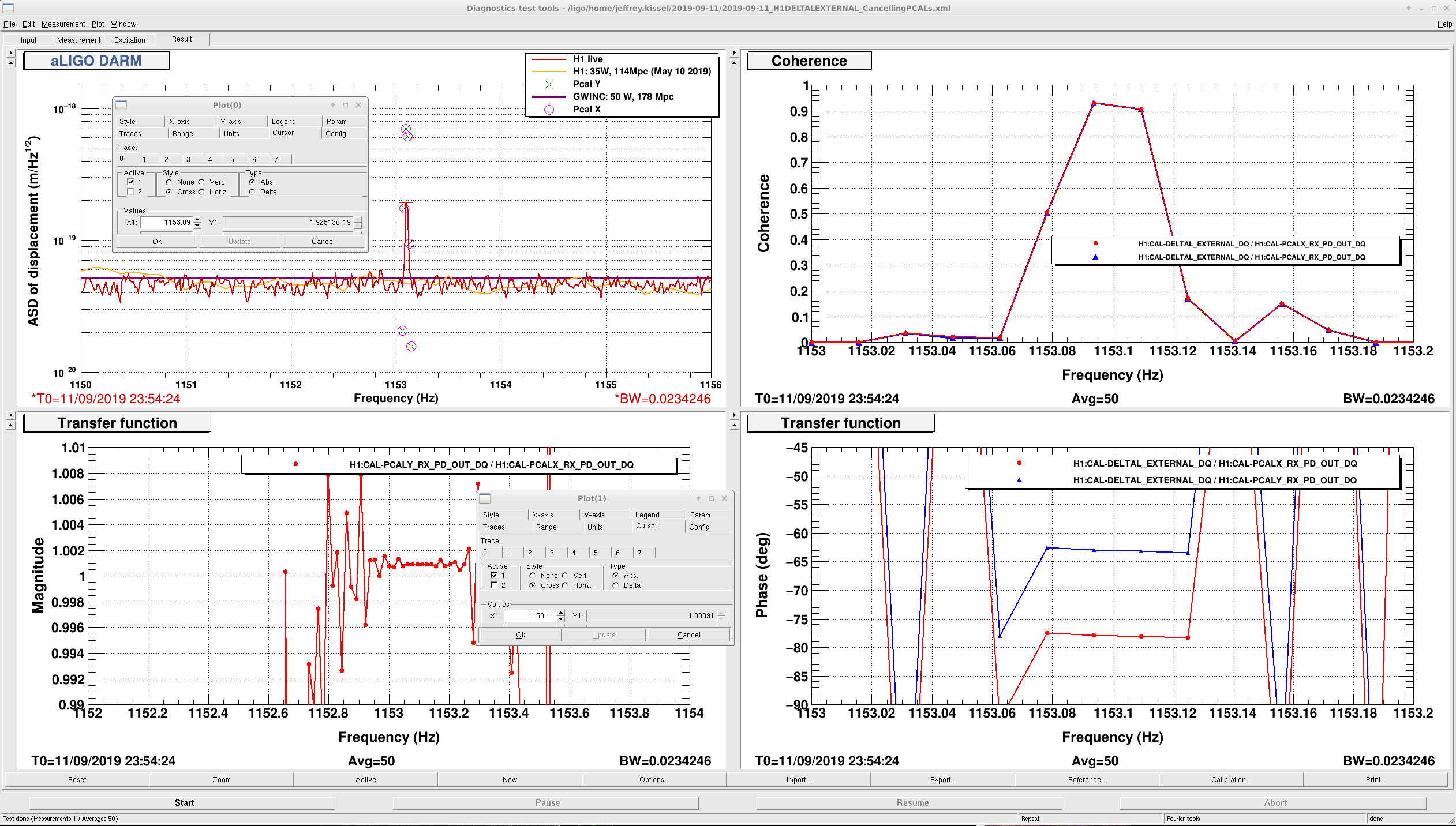
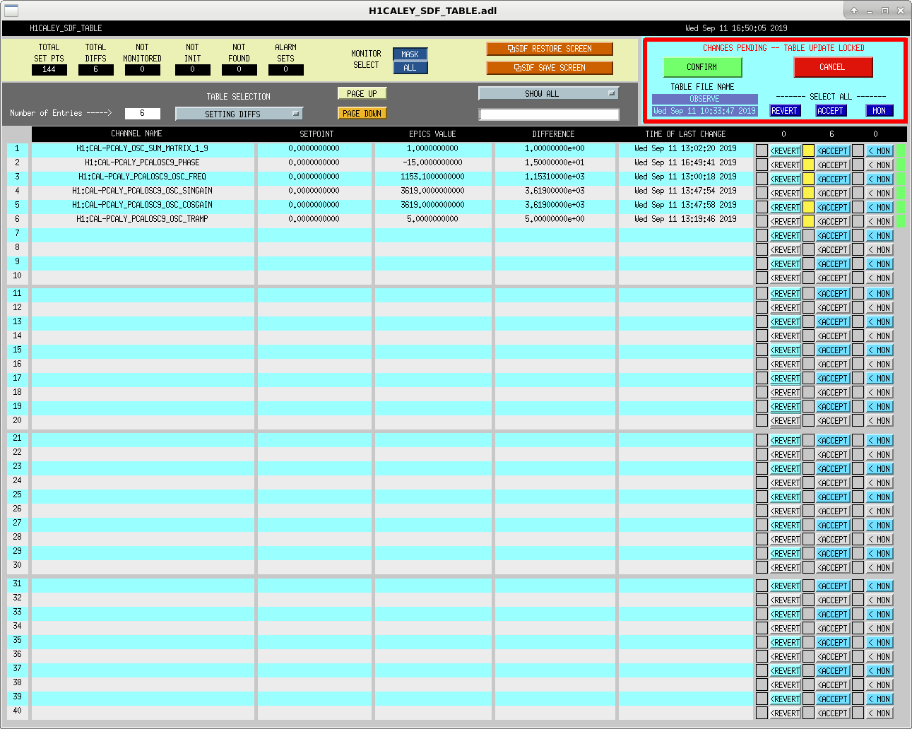
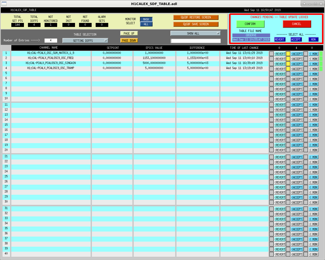
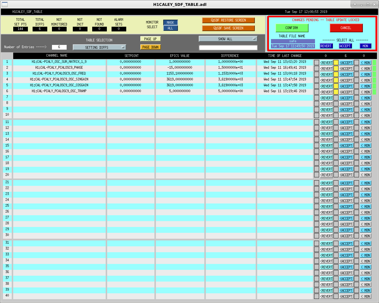
J. Kissel More details to come later, but in order to continue the investigation of a potential ~1% level systematic error between H1 PCALX and H1 PCALY (see IIET Ticket 13577), I spent today's commissioning time parasitically tuning the amplitude and phase of a "cancelling" line, in which the same amplitude of PCALX and PCALY line is injected at slightly different phase, so as to leak a little bit of DARM motion into DELTAL_EXTERNAL at exactly 1153.1 Hz. As a result of the tuning choices, the residual amount of DARM at that frequency I've left in DELTAL External is a factor of 4 above the noise floor in an ASD with frequency resolution of 0.02 Hz. This yields residual coherence between each PCAL and DELTAL EXTERNAL of 0.9, which should be plenty enough SNR to track ~1% or better level changes and discrepancies between these two PCALs. Note, also, that these extra lines do not stress the limits of actuation range for either PCAL -- I was running these lines while all normal calibration lines and CW injections were running, including the PCALX high frequency roaming line, which happens to currently be at its highest frequency and loudest requested drive in the long duration sweep. The first observation segment with this line installed is Sep 11 2019 23:51:24 UTC, and the intent is to leave it in indefinitely or at least for the foreseeable future. The settings corresponding to this additional line have been accepted in to the SDF system. The lines have been installed in the 9th oscillator, H1:CAL-PCAL[X,Y]_PCALOSC9_OSC, with individual amplitudes installed in such a way that the excitation results in equal *displacement* (to within 0.1%) as reported by the calibrated receiver photodiode signals, aka the RX PDs. The excitations requested of the DAC are not calibrated, and thus the funny differing amplitudes *requested* of 5000 ct on PCALX and 3619 ct on PCALY. The -15 deg phase installed on PCALY was the result of the above mentioned tuning.