J. Kissel

H1 has been using the same reference DARM loop calibration model parameter set for all of O3 thus far (modelparams_H1_20190416.py). However, much has changed with the IFO and our understanding of it since then, and it's time to update. This aLOG describes why we're (finally) updating, what we've updated to, using what data sets, the new associated uncertainty it will bring, and all the scripts, process, and effort to make the self-consistent new parameter set and uncertainty (one person, two 16 hours days, an answer 3 days *before* installation -- record time!). The model will be installed, and the calibration will be updated on Monday, 2019-09-09, with the installation to begin around 9:30a PDT and will take effect the next indicated observation /analysis ready segment (don't worry, once that segment has started and its start time known, I'll be sure to communicated that far and wide).

Why: Here're the major things that have changed:
    (1) We've increased our laser power in to the IFO from "35 Watts" to "37 Watts" (see LHO aLOG 51734 for discussion of why I put those numbers in quotes) on Jun 10th. However, we contested that because our time-dependent correction factors (TDCFs) are correctly capturing them, and we're correcting for them down-stream in our low-latency h(t) production (aka GDS-CALIB_STRAIN), (and (2) was still happening) it was not worth the effort to update the front-end calibration (aka DELTAL_EXTERNAL). This meant that \kappa_C (the correction for optical gain change, say, due to laser power increase) has been perpetually ~0.96 %, which results in the niggling discrepancy we've seen on the Inspiral Range Figures of Merit comparing "the answer" from the two data streams (see e.g. the summary page plot from today).
    (2) We've drastically reduced the amount of confusion that we've had with the low frequency, opto-mechanical response (aka the sensing function) of the detector by installing a digital, length offset in the signal recycling cavity, and thus reducing the detuning of the cavity that we've had (the so called permanent 100 ct SRCL offset; see LHO aLOG 51592). This offset also has slightly improved / increased our DARM coupled cavity pole frequency. Still some confusion remains, but little enough that we don't think we need to include static compensation for detuning in our model of the sensing function, taking the hit terms of an unknown systematic error. This error is significantly less than what we've ascribed previously (see conclusions in for data up through August in G1901479). Further, we've found that our MCMC algorithm can handle the data again, which means we no longer have to use a model that barely represents what we measure, and we can again have a self-consistent uncertainty budget.
    (3) We found a way to re-install PUM L2A decoupling filters, reducing global ASC motion (have our cake, see LHO aLOG 51604) and with a new topology (LHO aLOG 49825), it no longer creates parasitic L2A2L, low frequency distortions of the PUM's L drive to TST L displacement (and it eat it too, see LHO aLOG 51782 and references therein)
    (4) We've found a small change in the actuation authority distribution, a boost of a factor of ~3 at 0.2 Hz, tapering off to a factor of 2-ish below that on the UIM stage (see LHO aLOG 51740), relieving some control from the PUM stage, which may have caused some lock losses due to saturation.

With these cumulative changes, and a model that matches our data self-consistently, it's time we update the calibration in the front-end and improve the accuracy of our low-latency data.

What, How, What Data Sets, Process, and Cognizent Decisions Along the Way:

The new model parameter set lives here:
    ^/trunk/Runs/O3/H1/params/modelparams_H1_20190909.py rev 8365

The only things that differ from the previous model,
    ^/trunk/Runs/O3/H1/params/modelparams_H1_20190416.py rev 7237
are the some of the optical response "sensing function" parameters, which are now
    # (from MCMC fit of 2019-09-04 'nominal config' data, restricted to above 20 Hz)
    ccOpticalGain = 3.181e+06 #cnts/meter
    ccPoleFreq = 411.2929     #Hz
    detuneSpringFreq = 0.0    #Hz MCMC fit is 0.13 Hz, but consistent with zero so install no detuning frequency.
    detuneSpringQ = 1e-2      #   MCMC fit is 1.87, but consistent with no spring, so install no detuning Q.

    # *Rough* Conversion from DARM IN1 [ct] to Current on DCPDs [mA]
    # Transfer function magnitude H1:OMC-DCPD_SUM_OUT_DQ/H1:LSC-DARM_IN1_DQ (entirely digital, but needs to be in NLN data stretch)
    # 5 Hz value at "start" time from above, 25 avgs, 0.1 Hz binwidth DTT FFT
    omcdcpdout2darmin1tf = 1.362605e6 # Mean of 2019-08-21, 2019-08-28, and 2019-09-04 values, std(values)=0.07% >> doesn't change appreciably.

    # GDS Compensation for Bad Foton Filter Approximation for 7 kHz High Frequency Roll-Off of 1/C
    # (from MCMC fit of 2019-09-04 'nominal config' data, restricted to above 20 Hz)
    # O3B_D2N = zpk([413.5227],[7000],1,"n")
    # O3B_Gain = gain(3.149e-07)
    CfotonInvSensingTF = SVNROOT+'trunk/Runs/O3/H1/Measurements/Foton/2019-09-09_H1CALCS_InverseSensingFunction_Foton_SRCD-2N_Gain_tf.txt' #export
and on the actuator side, the filter file and what's in use from that filter file for ETMX on the UIM (L1) stage
    AfilterFile_X = SVNROOT+'trunk/Common/H1CalFilterArchive/h1susetmx/H1SUSETMX_1251574934.txt' # Sep 03 2019 19:41:56 UTC

    UIMlockName = 'ETMX_L1_LOCK_L'
    UIMlockModules = [2,10] # Here's the new UIM Boost "muBoost" in FM2. JSK 2019-09-05, see LHO aLOG 51709
    UIMlockGain = 1.06

I'll start with the actuator, 'cause there hasn't been much change there: as discussed in LHO aLOG 51782, we see no change in frequency response of the any of the three stages of SUS ETMX used for DARM control, UIM (L1), PUM (L2), or TST (L3) as a result of either of the changes (3) or (4) above. Thus, all we need to do here, is update the copy of the foton file, and let the model know to use that new filter.
As bonus, that means several things for the uncertainty / systematic error estimate for the actuator:
    (a) We don't need to update the actuation strength estimate, so we can use the same values and MCMC posterior distributions of uncertainty on these parameters that we've been using all along throughout O3. Much less work! Good! We'll continue to use
    HDF5_A_MCMCresults=/ligo/svncommon/CalSVN/aligocalibration/trunk/Runs/O3/H1/Results/Uncertainty/O3_H1_A_MCMC_20190404.hdf5 rev 7476
    (b) We can just lump these latest measurements into our collection of data sets that inform the unknown systematic errors in frequency dependence for each stage. With these new data sets, the uncertainty on that unknown systematic error will improve.
    (c) With the new found better understanding of where to restrict the frequency range of MCMC fit, and how to use the Gaussian Process Regression fitting tool to estimate that unknown systematic error (see G1901479, and discussions of length scale and frequency range), we can refine our estimate further.

All that culminates in a new and improved uncertainty estimate (from the improved uncertainty in unknown systematic error) for the actuator.
The script I used that produce the updated unknown systematic error estimate is
    ^/trunk/Runs/O3/H1/Scripts/Uncertainty/process_allmeas_writeGPRHDF5_model20190909-A.py rev 8389

See the first six .pdf attachments, 2019-09-04_H1_???_actuationMeasurement_allresiduals_MCMCInput.pdf and H1_model2019-09-09_meas2019-09-04_???_actuationMultiGPR.pdf which show the collection of measurements used (first set), and the resulting fit for unknown systematic error (second set).

Now to the more complicated part: the changes in sensing function parameters and their associated parameter uncertainty, and contribution to response function uncertainty.
     (a) We've collected, now, 4 data sets in the current sensing function configuration: the restored "July" spot positions, and *with* a digital 100 ct SRCL offset: 2019-08-21, 2019-08-28, and now two data sets that turned out to be not that different on 2019-09-04. Like Evan did for his update of the uncertainty for C01 (again see G1901479), I asked -- "how different of parameter answers and/or goodness do we get if we MCMC over the entire frequency span of the data set, or just restrict it frequencies which we believe can be well-explained by our model?" After looking at 8 different MCMC results -- a fit range of 5 to 5000 or 20 to 2000 for all 4 data sets -- I came to the conclusion that a lower limit of 20 Hz gave better, more consistent results AND for the following reasons, I used the 2019-09-04 "nominal config" (i.e. no PUM L2A decoupling and UIM boost OFF) :
    - Gives best results for MCMC fit (small frequency-dependent residuals between fit and measurement)
    - Gives "middle of the road" f_cc, and f_s values (comparing the answers from all the >20 Hz data)
    - Optical gain is with the 0.5% variance of all fit answers for optical gains
    - f_s values are all consistent with zero, so OK to choosing to enter 0 Hz (no) spring in foton, and install model with 0 Hz (i.e. no) detuned spring.
    - Intentionally not using averaging of all dates, because we need to have representative MCMC posteriors for each parameter to have self consistent model and implementation.
The results for that fit on the 2019-09-04 nominal config data, with 20 > f_fitRange > 5000 are

    Optical gain, H_c (ct/m)                 | 3.181e+06 (+ 958,-958.7) or (+0.03012%,-0.03014%)
    Optical gain, H_c (mA/pm)                | 4.334 (+0.001305,-0.001306) or (+0.03012%,-0.03014%)
    Cavity pole, f_cc (Hz)                   | 411.2929 (+0.7354,-0.7224) or (+0.1788%,-0.1756%)
    Detuned SRC spring frequency, f_s (Hz)   | 0.1345 (+0.1005,-0.04764) or (+74.75%,-35.43%)
    Detuned SRC spring quality factor, Q_s   | 1.872 (+3.464,-4.302) or (+54.05%,-43.52%)
    Residual time delay, tau_c (usec)        | -1.252 (+0.4738,-0.4692) or (+-37.83%,--37.46%)
and thus the chosen parameter values. I'll highlight that the f_s value is consistent with zero, so I've chosen to install model parameters that force no detuning.

The two attachments 2019-09-04_H1_fmin20Hz_sensingFunction_mcmcModel_vs_measurement.pdf and 2019-09-04_H1_fmin20Hz_sensingFunction_mcmcModel_paramCornerPlot.pdf show the MCMC fit and the corresponding posterior distribution corner plot for 2019-09-04, "nominal config" data.

     (b) The script to process that particular fit and save the posterior distribution on those parameters is
         /ligo/svncommon/CalSVN/aligocalibration/trunk/Runs/O3/H1/Scripts/FullIFOSensingTFs/
              process_sensingmeas_20190904_nomconfig.py rev 8368
         which spits out (upon request, I've relearned by calling an extra function writeSensingMCMCposteriorsHDF5 from /ligo/svncommon/CalSVN/aligocalibration/trunk/Common/pyDARM/computeDARM.py src7213) an .hdf5 file recording the posteriors here
         /ligo/svncommon/CalSVN/aligocalibration/trunk/Runs/O3/H1/Results/Uncertainty
              O3_H1_C_MCMC_20190904_nomconfig_fmin20Hz_finaltrial.hdf5  rev. 8364
         I re-learned the hard way that these need to be done once you like the results of the MCMC fit -- and sadly, sometimes the fit gives irreproducible results, so if you get one set of a parameter answers you like one day, then come back the next and actually write the answers to file, your MAP values may be inconsistent -- especially if the posterior distribution is non-Gaussian like we have!

     (c) Armed with a set of Maximum A-Posteriori (MAP) values, I can then update the model parameter set (see above), AND also generate the export of foton's bad approximation to the near-nyquist 7000 Hz pole necessary to roll off the inverse sensing function filter that gets installed in the front-end, hence,
        /ligo/svncommon/CalSVN/aligocalibration/trunk/Runs/O3/H1/Measurements/Foton/2019-09-09_H1CALCS_InverseSensingFunction_Foton_SRCD-2N_Gain_tf.txt
        NOTE: the MCMC fit analysis code assumes we'll be using the MAP values, so it gave me the following foton design string to install and export:
            SRCD2N: zpk([411.2929;0.1033;-0.1751],[0.1;0.1;7000],1,"n")gain(1.81)
            Gain: gain(3.144e-07)
        However, because as discussed in (a) I've intentionally installed NO detuning in the model, so I instead used the following design string for the export:
            zpk([411.2929],[7000],1,"n")

     (d) Finally, given that we have 4 data sets of the sensing function in the same configuration, it makes sense to estimate the unknown systematic error -- i.e. make sure we cover what's left over of the confusing low-frequency response as an element to our response function uncertainty. So I collected the afore mentioned 4 data sets and played the GPR fitting parameter game until I was satisfied, using the following script:
         /ligo/svncommon/CalSVN/aligocalibration/trunk/Runs/O3/H1/Scripts/Uncertainty/
             process_allmeas_writeGPRHDF5_model20190909-C.py  rev 8370
         and saved the results to
         /ligo/svncommon/CalSVN/aligocalibration/trunk/Runs/O3/H1/Results/Uncertainty/
             O3_H1_C_GPR_20190909_multi_nofsQcorr_fmin20Hz_lengthscaleZp5.hdf5  rev. 8371

The collection of data compared against the new model is shown in attachment 2019-09-04_H1_20190909Model_sensingFunction_referenceModel_vs_allMeasurements.pdf and the GPR fit for it is H1_allO3BMeas_nofsQcorr_fmin20Hz_lengthscaleZp5_model2019-09-09_meas2019-09-04_sensingFunction_GPR.pdf.

Oooooh kay! Kudos to you if you've even made it this far in the reading. #kLOG.

Associated Uncertainty
Now, armed with the actuation function's parameter uncertainty and unknown systematic error with its associated uncertainty, and the same for the sensing function, we can produce a response function uncertainty, using
    /ligo/svncommon/CalSVN/aligocalibration/trunk/Common/pyDARM$
        RRNom.py rev 8377
This is unfortunately a function, in which the list of arguments is longer than my arm, so I'll explicitly report it here for future reference (the python3 part is necessary):
    python3 RRNom.py --IFO=LHO --HDF5_A_MCMCresults=/ligo/svncommon/CalSVN/aligocalibration/trunk/Runs/O3/H1/Results/Uncertainty/O3_H1_A_MCMC_20190404.hdf5 --HDF5_A_GPRresults=/ligo/svncommon/CalSVN/aligocalibration/trunk/Runs/O3/H1/Results/Uncertainty/O3_H1_A_GPR_20190909_multi.hdf5 --HDF5_C_MCMCresults=/ligo/svncommon/CalSVN/aligocalibration/trunk/Runs/O3/H1/Results/Uncertainty/O3_H1_C_MCMC_20190904_nomconfig_fmin20Hz_finaltrial.hdf5 --HDF5_C_GPRresults=/ligo/svncommon/CalSVN/aligocalibration/trunk/Runs/O3/H1/Results/Uncertainty/O3_H1_C_GPR_20190909_multi_nofsQcorr_fmin30Hz_lengthscaleZp5.hdf5 --modelPath=/ligo/svncommon/CalSVN/aligocalibration/trunk/Runs/O3/H1/params/ --modelFilename=modelparams_H1_20190909 --IFOmodel=modelPars --outDir=/ligo/svncommon/CalSVN/aligocalibration/trunk/Runs/O3/H1/Results/Uncertainty/ --plot1SigmaUncs --plotSamplesAndUncs --sampleNumber=1000 --seed=1234 --version=ref --saveSummaries --gpsTime=1251687618 --PcalSweepData=/ligo/svncommon/CalSVN/aligocalibration/trunk/Runs/O3/H1/Measurements/FullIFOSensingTFs/2019-09-04_H1_NominalConfig_PCAL2DELTAL_LF_SS_A_PCALYRX_B_DELTALEXT_tf.txt --GetData=GWPY
There's probably some parts of this I don't need, but I was follow as best I could from the README here:^/trunk/Common/pyDARM/README rev. 8379

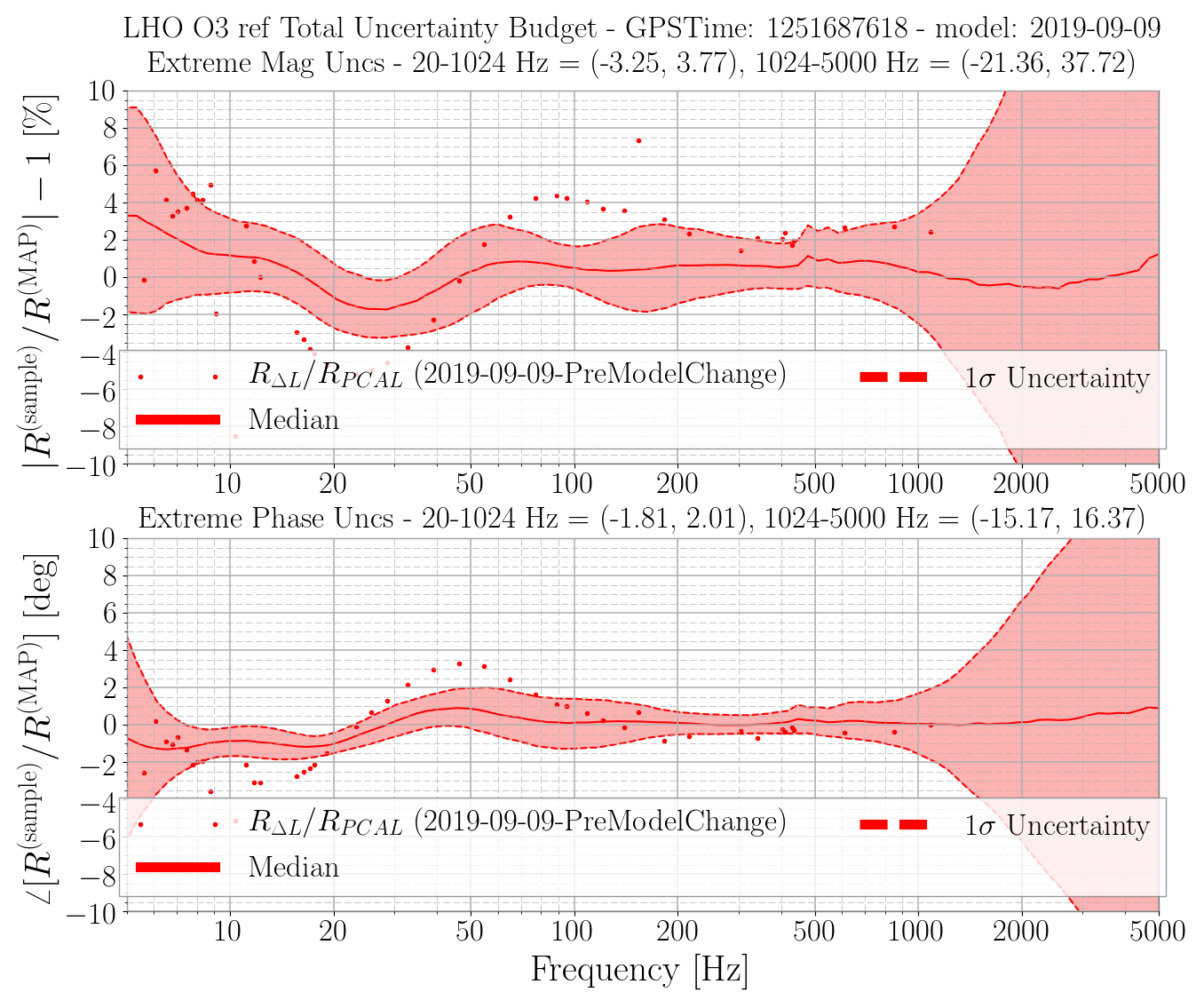
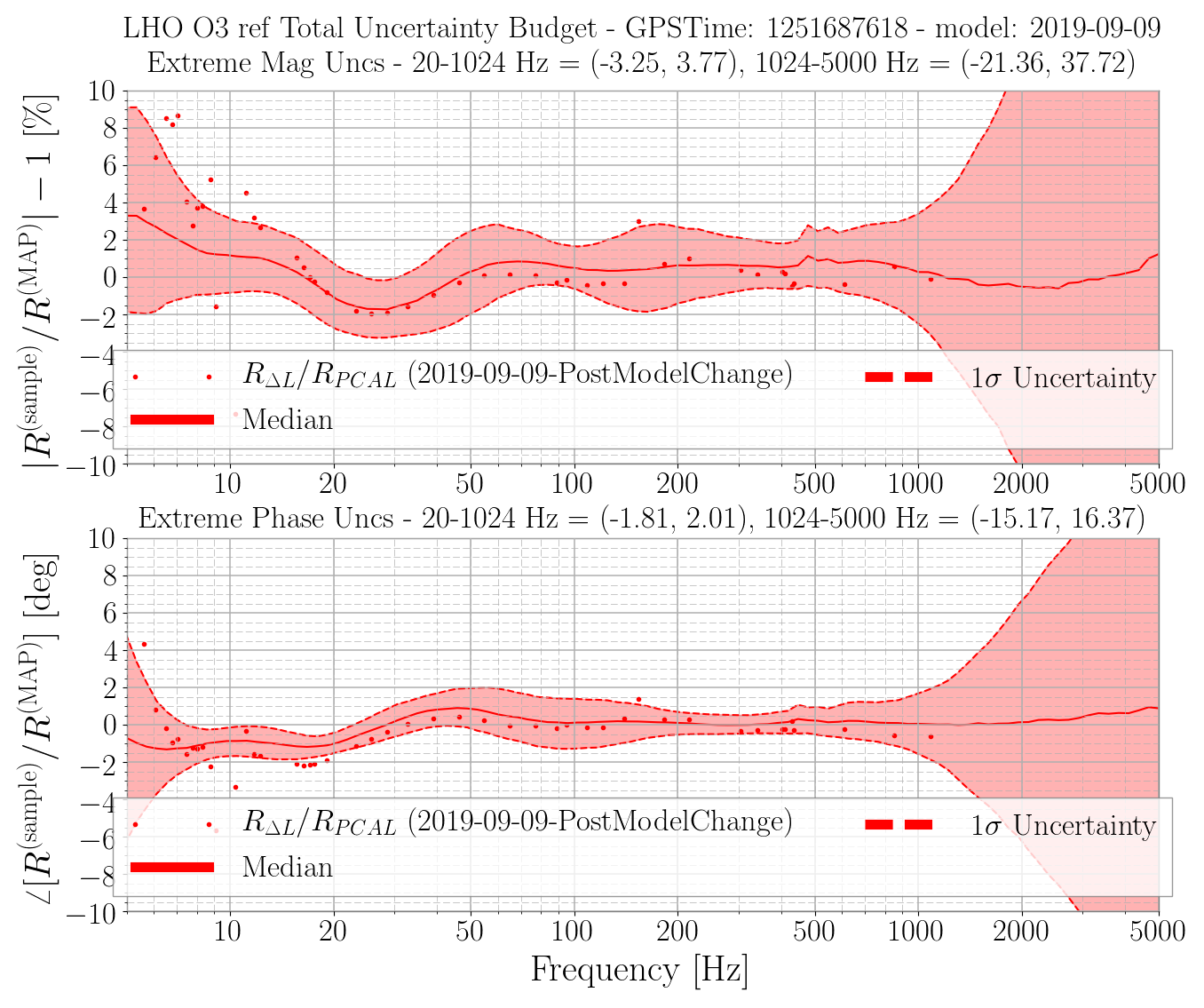
The results are the only image attachment, 2019-09-06_O3_LHO_GPSTime_1251687618_ref_RelativeResponse1SigmaUncertainty.png.

One can see that the maximum 68% ci bounds of the frequency region from 20-1024 Hz on the response function uncertainty and systematic error are 3.77% and 2.01 degrees.
This is better than reported for C01 at the start of O3 through Jun 11th, over a similar frequency range -- most-notably around 20-30 Hz where we've reduced the uncertainty in (i) unknown systematic error for the sensing function by improving the low frequency response, i.e. reducing the SRC detuning, and (ii) unknown systematic error for the actuation function by adding more measurements and improving the Gaussian process regression parameters.

 for this reference model (remember, doesn't include the uncertainty of time-dependent correction factors determined from calibration line coherence)

Attached are all the plots that show the supporting data.
The plots live in the following locations in the repo (worth it to record here, because the results directories can be a mess of trials and errors), in order of attached list:
^/trunk/Runs/O3/H1/Results/Uncertainty/
    2019-09-04_H1_UIM_actuationMeasurement_allresiduals_MCMCInput.pdf
    2019-09-04_H1_PUM_actuationMeasurement_allresiduals_MCMCInput.pdf
    2019-09-04_H1_TST_actuationMeasurement_allresiduals_MCMCInput.pdf

^/trunk/Runs/O3/H1/Results/FullIFOSensingTFs/
    2019-09-04_H1_20190909Model_sensingFunction_referenceModel_vs_allMeasurements.pdf

^/trunk/Runs/O3/H1/Results/Uncertainty/
    H1_model2019-09-09_meas2019-09-04_UIM_actuationMultiGPR.pdf
    H1_model2019-09-09_meas2019-09-04_PUM_actuationMultiGPR.pdf
    H1_model2019-09-09_meas2019-09-04_TST_actuationMultiGPR.pdf

^/trunk/Runs/O3/H1/Results/FullIFOSensingTFs/
    2019-09-04_H1_fmin20Hz_sensingFunction_mcmcModel_vs_measurement.pdf
    2019-09-04_H1_fmin20Hz_sensingFunction_mcmcModel_paramCornerPlot.pdf

^/trunk/Runs/O3/H1/Results/FullIFOSensingTFs/
    2019-09-04_H1_20190909Model_sensingFunction_referenceModel_vs_allMeasurements.pdf

^/trunk/Runs/O3/H1/Results/Uncertainty/
    H1_allO3BMeas_nofsQcorr_fmin20Hz_lengthscaleZp5_model2019-09-09_meas2019-09-04_sensingFunction_GPR.pdf

^/trunk/Runs/O3/H1/Results/Uncertainty/
    2019-09-06_O3_LHO_GPSTime_1251687618_ref_RelativeResponse1SigmaUncertainty.png
    2019-09-06_O3_LHO_GPSTime_1251687618_ref_RelativeResponseUncertaintyBudget.png
    2019-09-06_O3_LHO_GPSTime_1251687618_ref_RelativeResponseUncertainty_FinalResults.txt
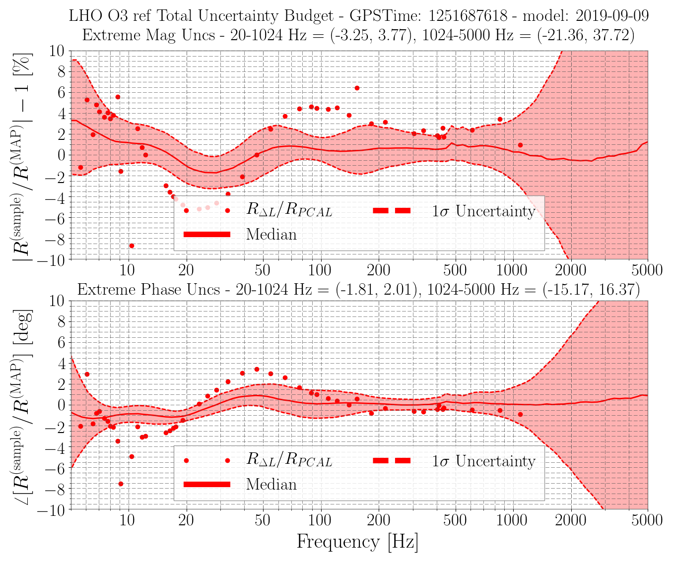


In the original alog, we see that the PCAL2DeltaL measurements do not agree with the envelope on the uncertainty plot. This is because the measurement was taken after the IFO changed but before the model was applied, i.e., the "Delta L" was not updated. Please see the three attached uncertainty plots with three sets of PCAL2DeltaL measurements: 0909PreModelChange, 0909PostModelChange, and 0916. It is clear that after the model change, the measurements 0909PostModelChange and 0916 both agree with the uncertainty envelope, but the one before the model change, 0909PreModelChange, does not agree with the envelope.
These plots are committed to ^trunk/Runs/O3/H1/Results/Uncertainty/PCAL2DARMvsUnc/
The command lines used to produced these plots are in ^trunk/Runs/O3/H1/Results/Uncertainty/PCAL2DARMvsUnc/commands.txt