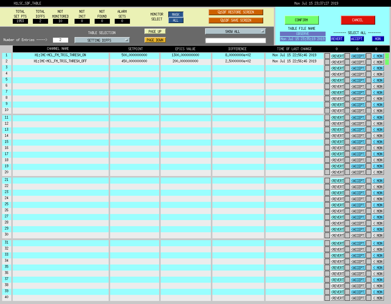
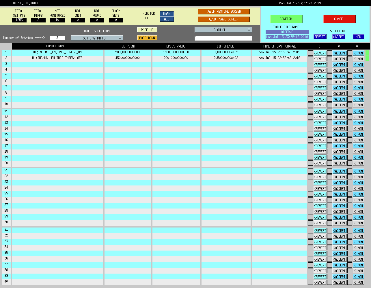
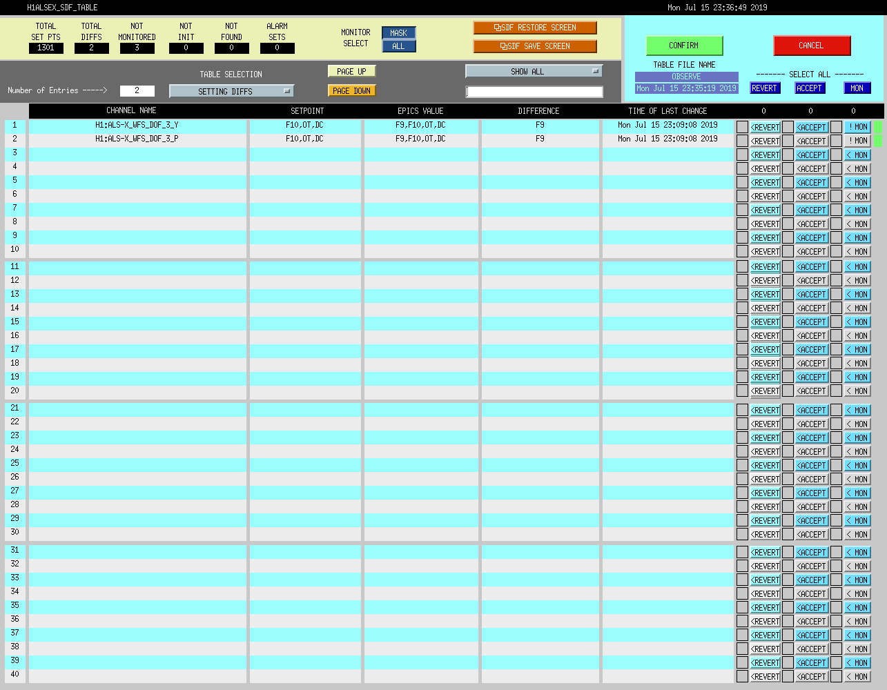
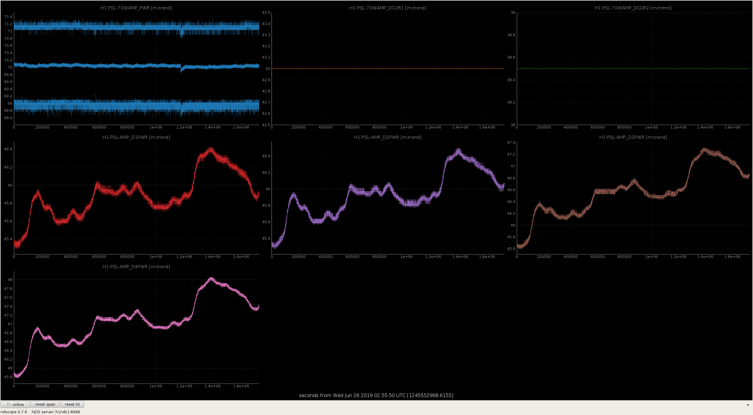
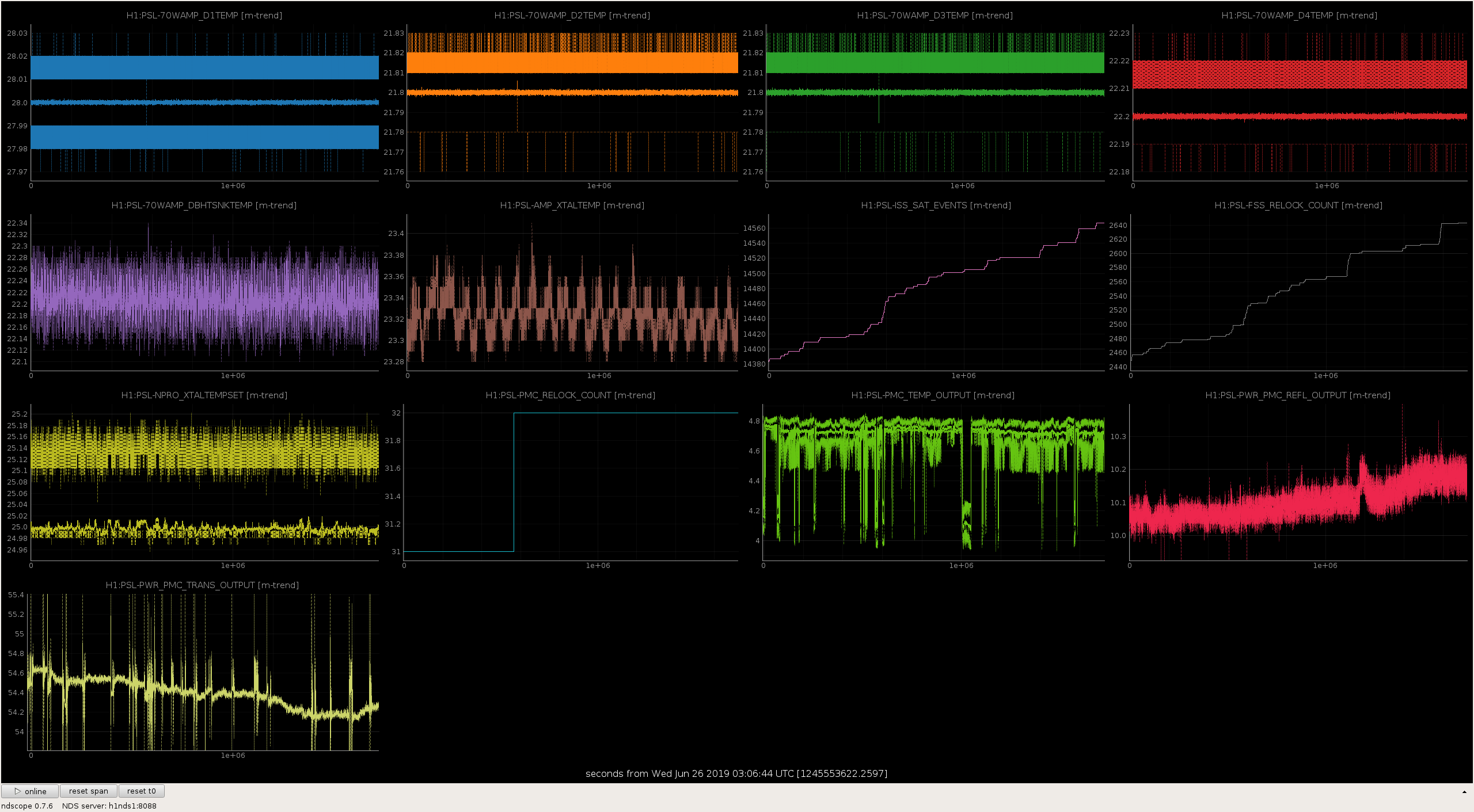
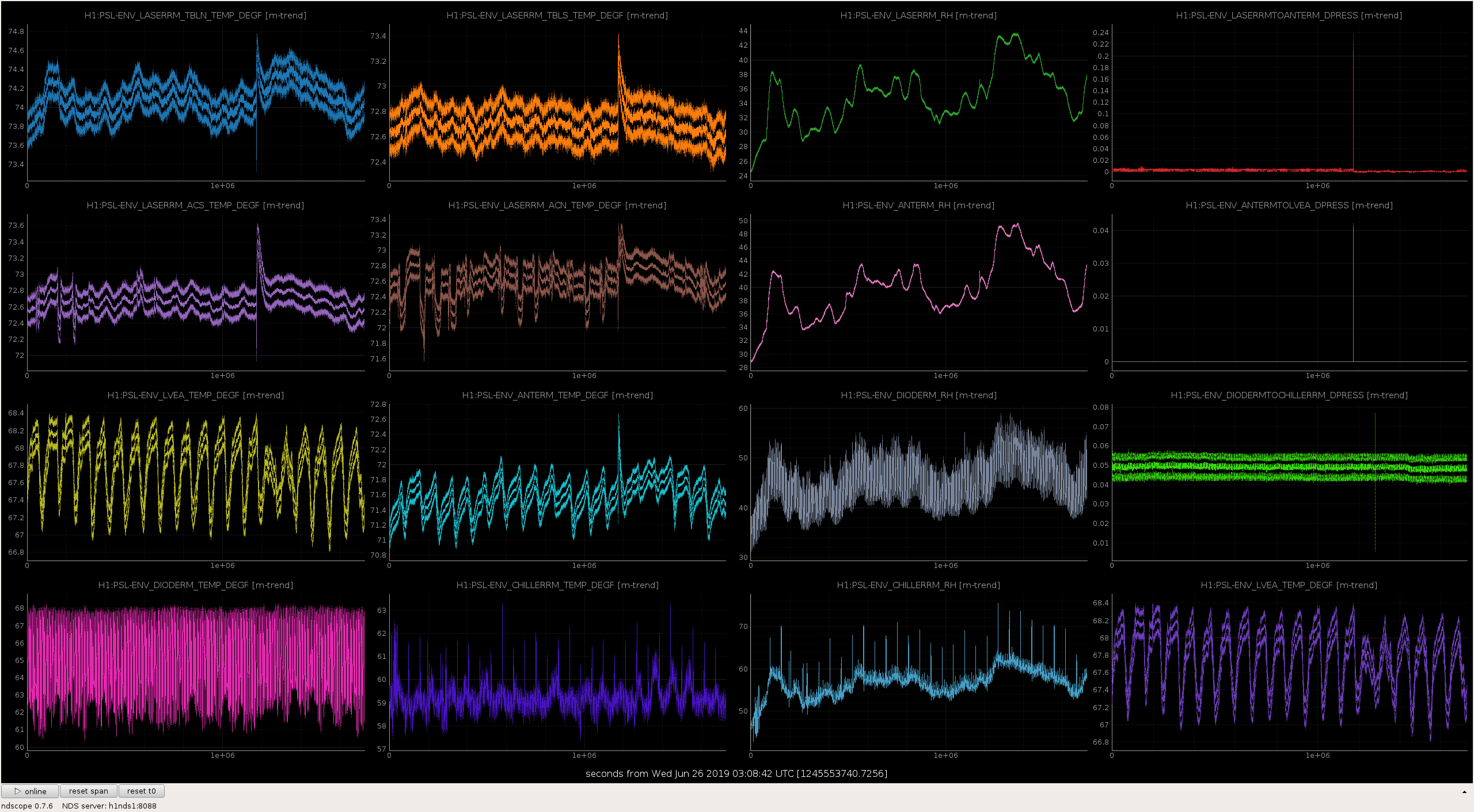
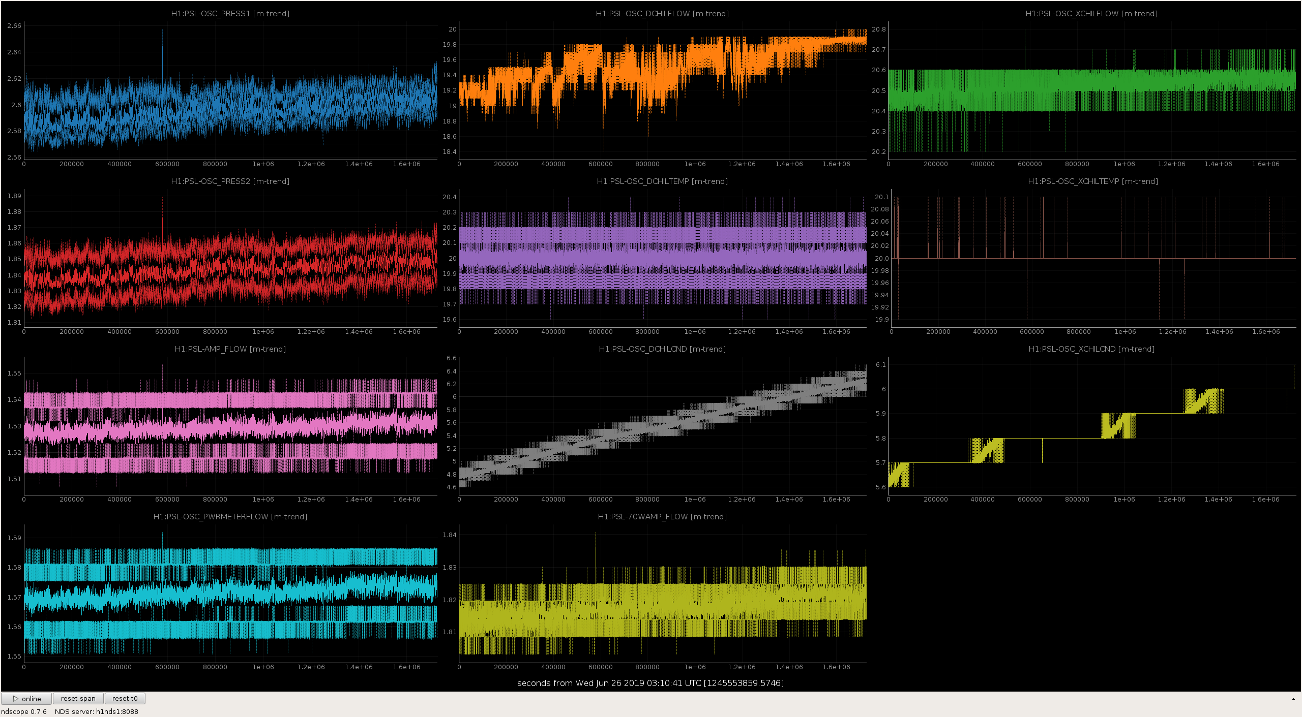
I swept the end stations and LVEA. Daniel is still working in the LVEA and will turn off the lights and WAP when he is done. Besides that, all good.
WP 8169
Isolated the cable trays from the cable tray supports with Teflon for the following racks:
1. PSL-R1
2. PSL-R2
3. ISC-R1
4. ISC-R2
5. ISC-R4
Isolation is to help control our ground points. Each rack is now tied to building ground at one dedicated point. Same work has been done at EX, EY, and HAM6 racks. See alog 49236 and 48539.
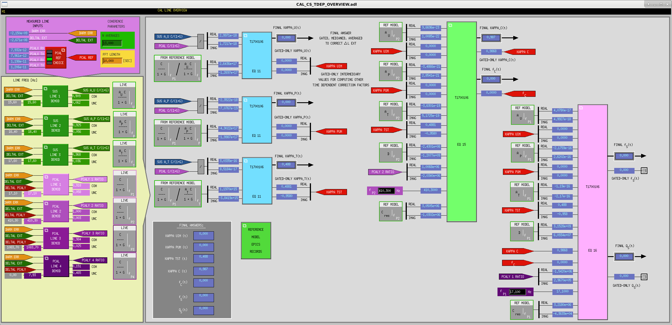
J. Kissel ECR E1900197 / IIET Ticket 13175 WP # 8277 I've taken Joe's instructions from LLO (see LHO aLOG 46978), and updated the h1calcs front-end code by compiling with updated library parts and c-code in the userapps repo, /opt/rtcds/userapps/trunk/cds/common/src/COH_GATE.c /opt/rtcds/userapps/trunk/cal/common/models/CAL_LINE_MONITOR_MASTER.mdl /opt/rtcds/userapps/trunk/cal/common/models/CAL_CS_MASTER.mdl I've also received his updates to MEDM screens, /opt/rtcds/userapps/trunk/cal/common/medm/CAL_CS_TDEP_OVERVIEW.adl /opt/rtcds/userapps/trunk/cal/common/medm/CAL_CS_TDEP_F_S_OVERVIEW.adl /opt/rtcds/userapps/trunk/cal/common/medm/CAL_CS_ACTUATION_FUNCTION.adl but noticed that he missed changing over the input labels and channels at the upper level of TDEP_OVERVIEW's calculation to the f_s and Q from LINE4, so I've switched things to LINE1. I've also added labels to the TDCF outputs just for extra readability of the screen. These changes have been committed to the repo. As a result of these changes, we expect: - Bug fix in the application of kappa_U and kappa_T to the CFTD_DELTAL_EXTERNAL path. - Update to the gating algorithm to better match the GDS pipeline. - We expect that the calculation of f_s and Q will now be restored (because we're using the "actuator" PCAL line at 17.10 Hz, instead of the now-defunct 7.93 Hz line). - Bug fix in some of the screen indications of what goes where (especially with kappa_U / kappa_P / kappa_T application in the CFTD path). The reference model parameters (i.e. what the calibration group calls "EPICS RECORDS") at the 17.1 Hz line frequency have already been installed (they came with the 2019-04-16 reference model push). Also, the phase modification to account for the clock-cycle difference between the corner station and end station computers, kept in the channel H1:CAL-CS_TDEP_PCAL_LINE1_PCAL_DEMOD_PHASE, was also installed during the reference model push. So -- the only thing I needed to change for switching over to the PCAL_LINE1 was to change the channel H1:CAL-CS_TDEP_D2N_SPRING_PCAL_FREQ to be set to 17.1. I've confirmed that we at least have all former TDCFs back up and running and are functional. Stay tuned regarding f_S, Q_s, and the CFTD path.
Maintenance activities were somewhat light, so started locking well before noon. Currently waiting for H1 to get to 2W for commissioning measurements by Sheila & Daniel (tried a few times so far, but H1 knocked out each time). Once they are set up for measurements, they should not take too long...but setting up has been knocking us out.
TJ currently out to SWEEP the EX & EY. (Still need to SWEEP the LVEA).
Daniel, Sheila
We caused two locklosses trying to replicate the measurement of the ratio of carrier and sideband powers (https://alog.ligo-wa.caltech.edu/aLOG/index.php?callRep=48595) at 2W. This should have been a quick check but wasn't because of the locklosses.
We got some time with the 9 MHz modulation depth increased and decreased before loosing lock: normally we run amplifier at 23 dBm while acquiring, we had the modulation depth increased to 25.2 dBm at 20:32:44 UTC July 16th and at 22.1dBm at 20:33:33 UTC before we lost lock.
We used the same script to change the modulation depth in full lock which scales all the appropriate gains, so I am not sure why we lost lock.
[Bubba Gateley, Jeff Kissel, Calum Torrie, Krishna Venkateswara, Eddie Sanchez, Rich Savage, Timesh Mistry]
This is a delay post from last week.
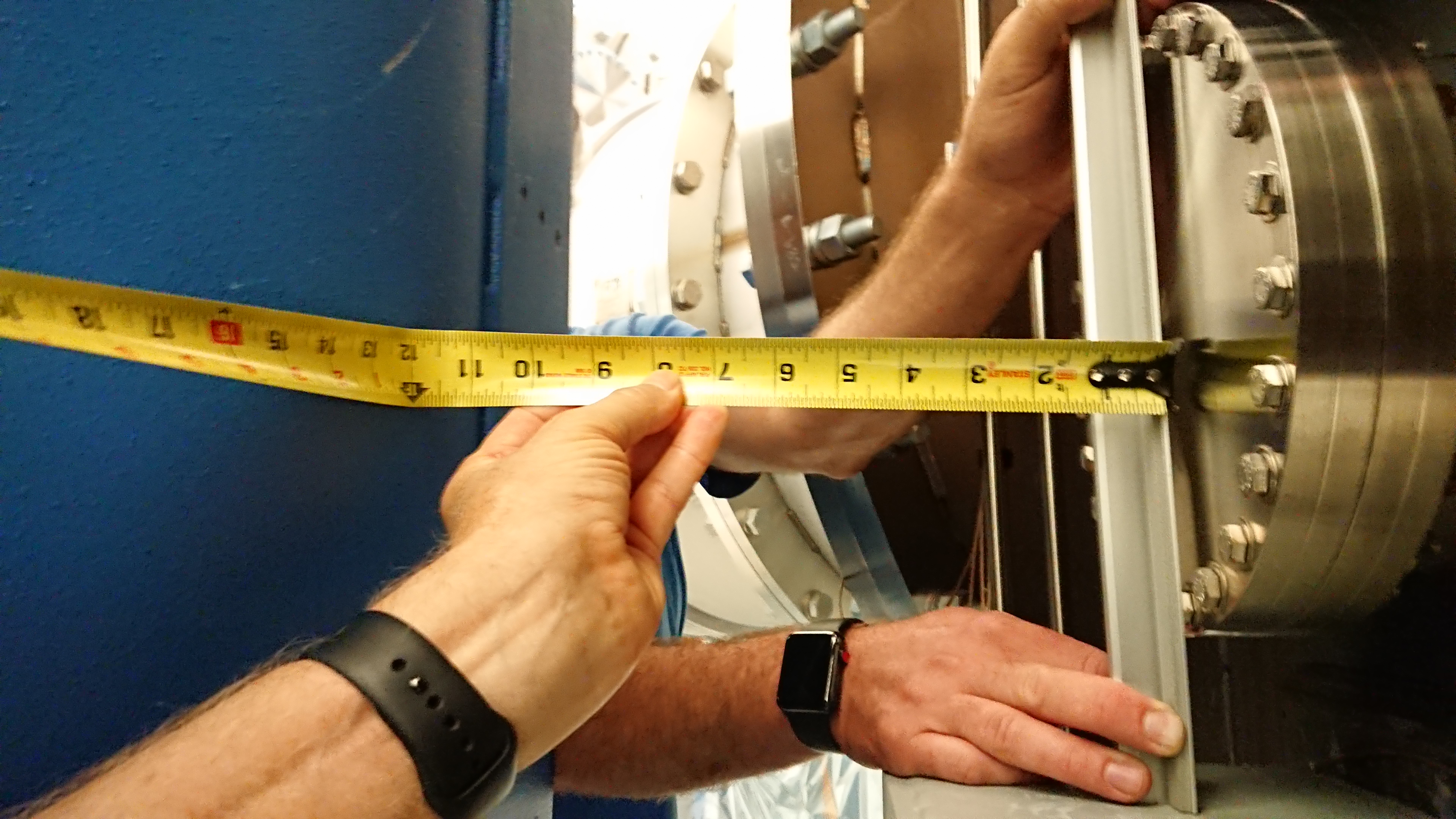
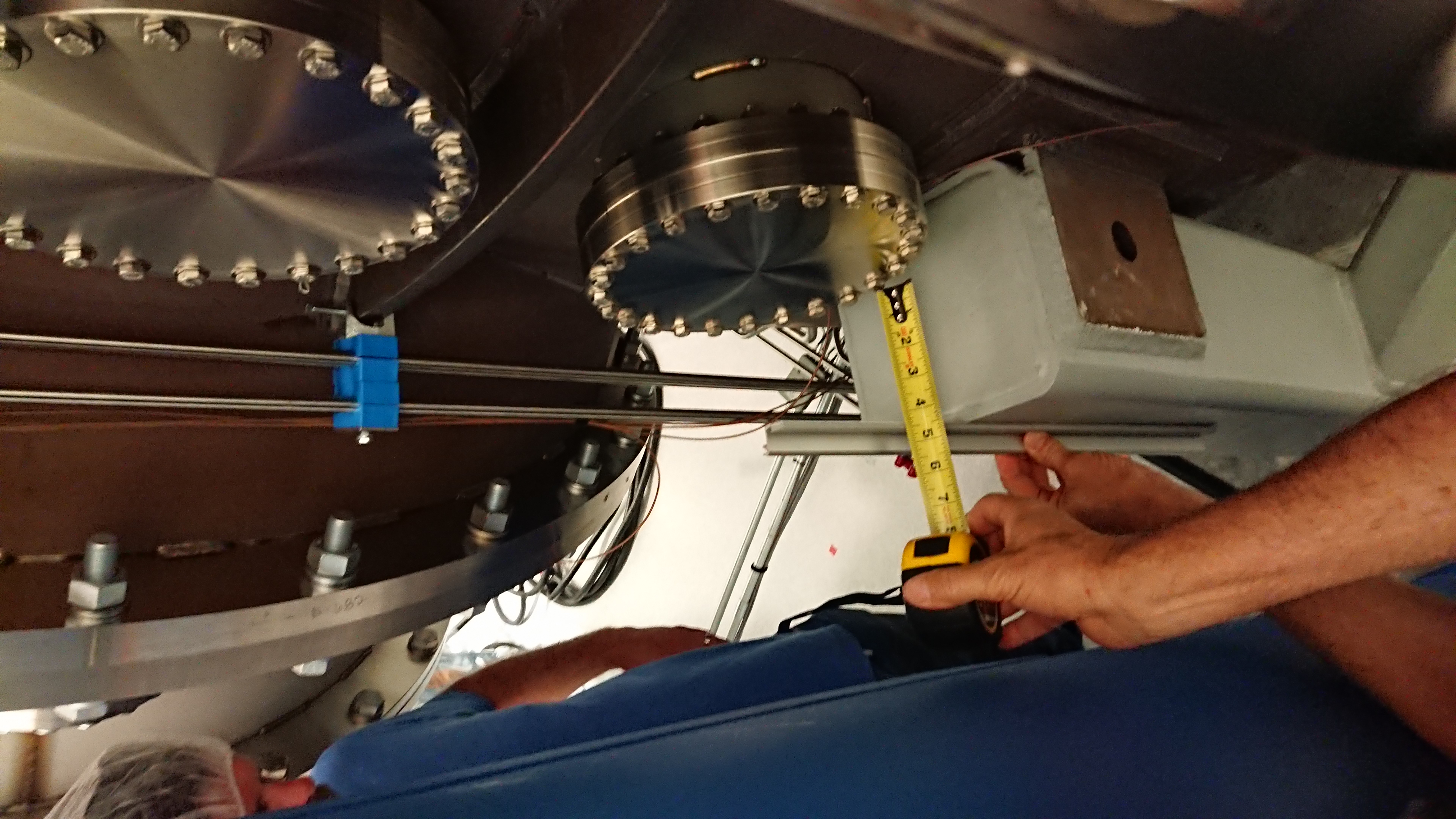
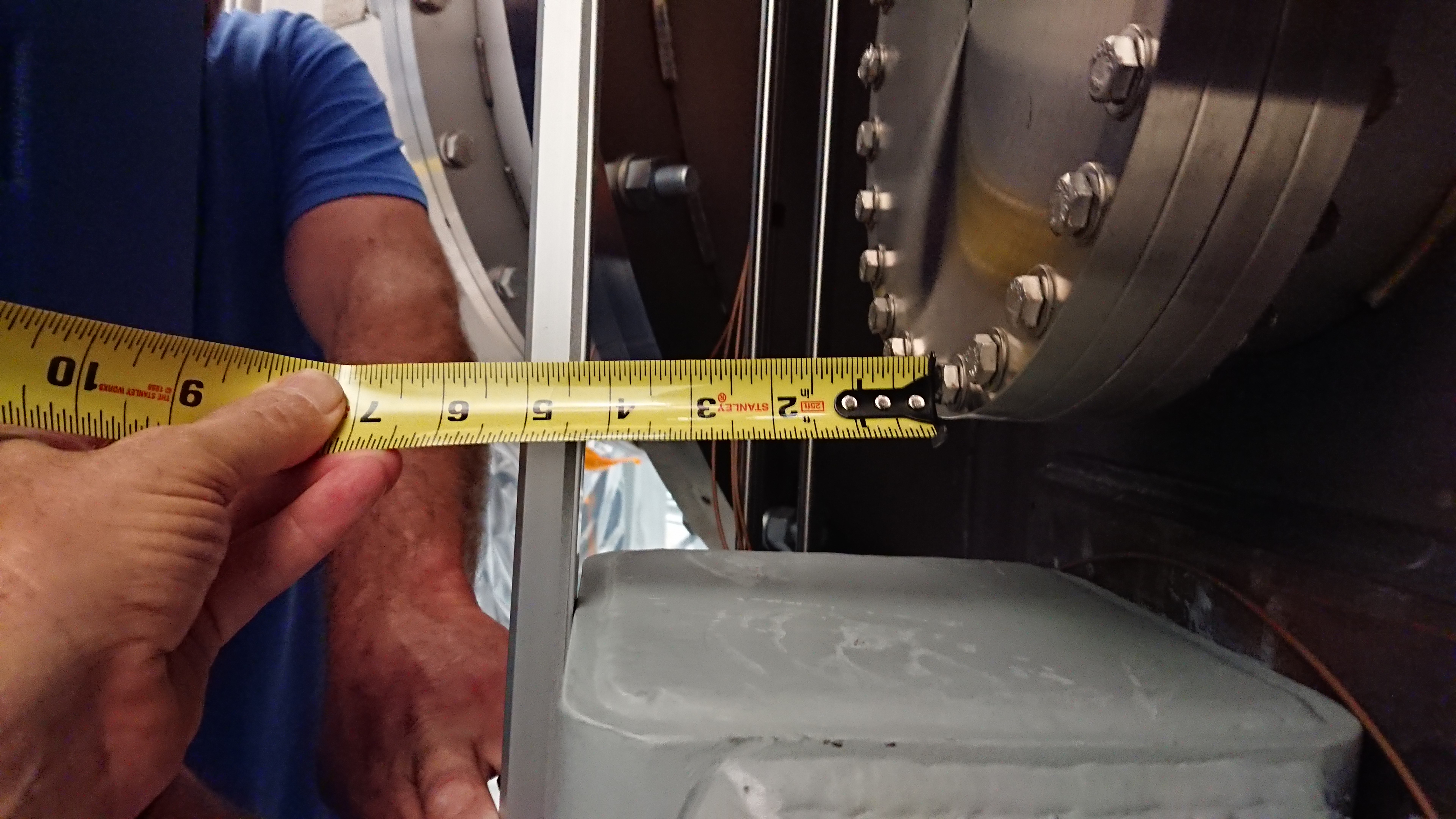
Rick and I went down to EX end station with a tape measure to see how much room there was to physically do the drilling. All the photos ca be found in the DCC G1901341 entry. The key photos will be attached here.
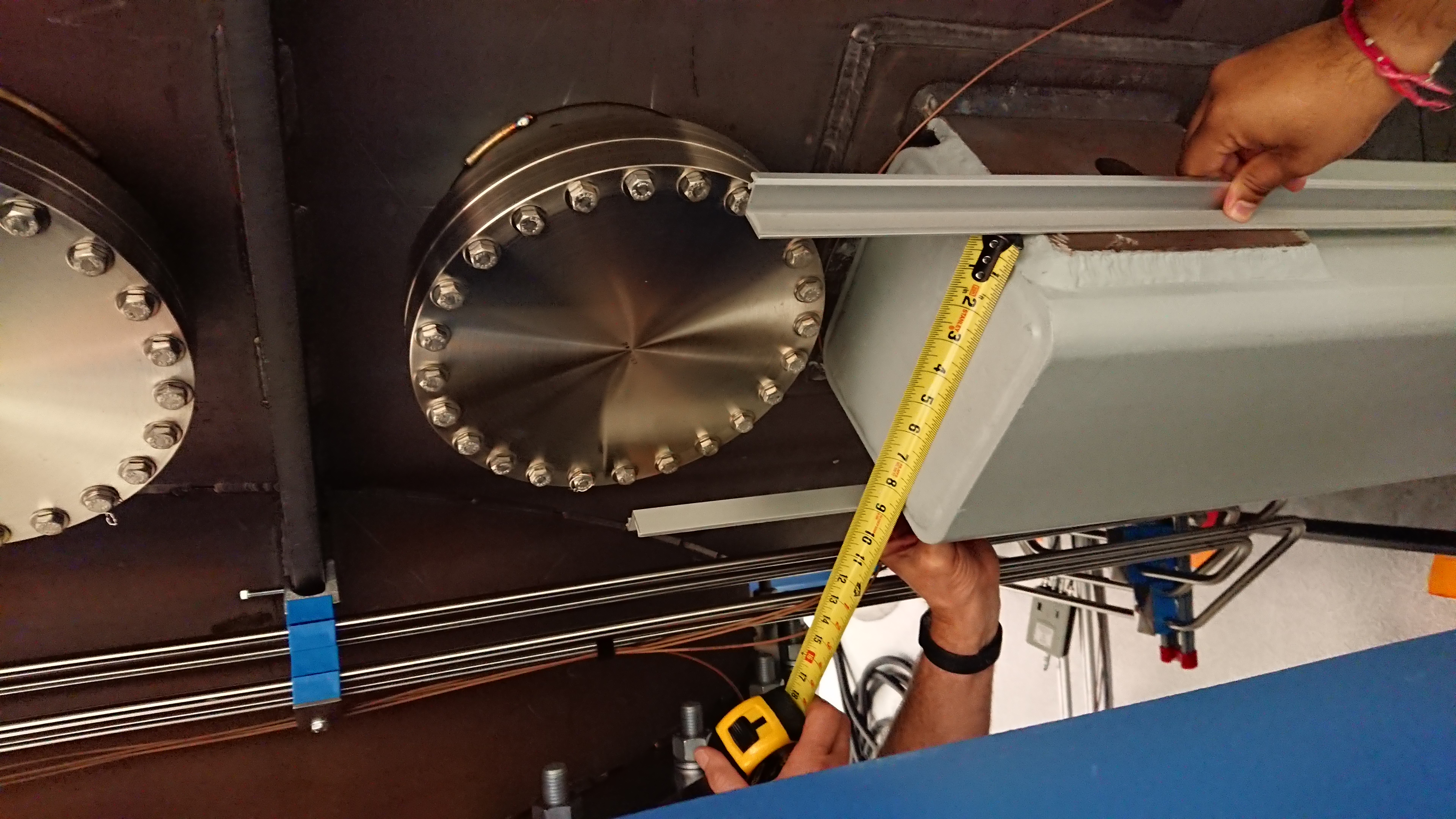
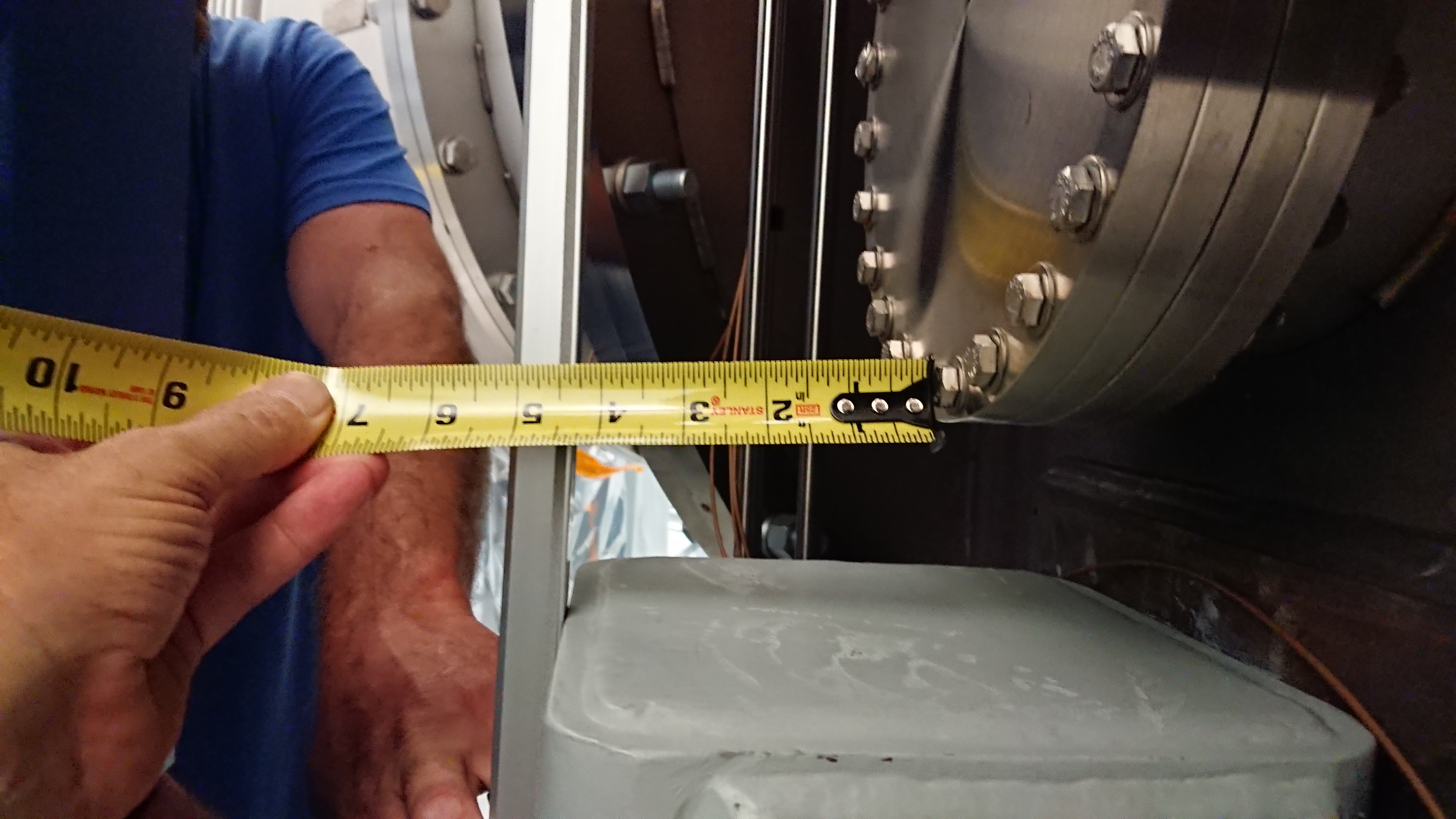
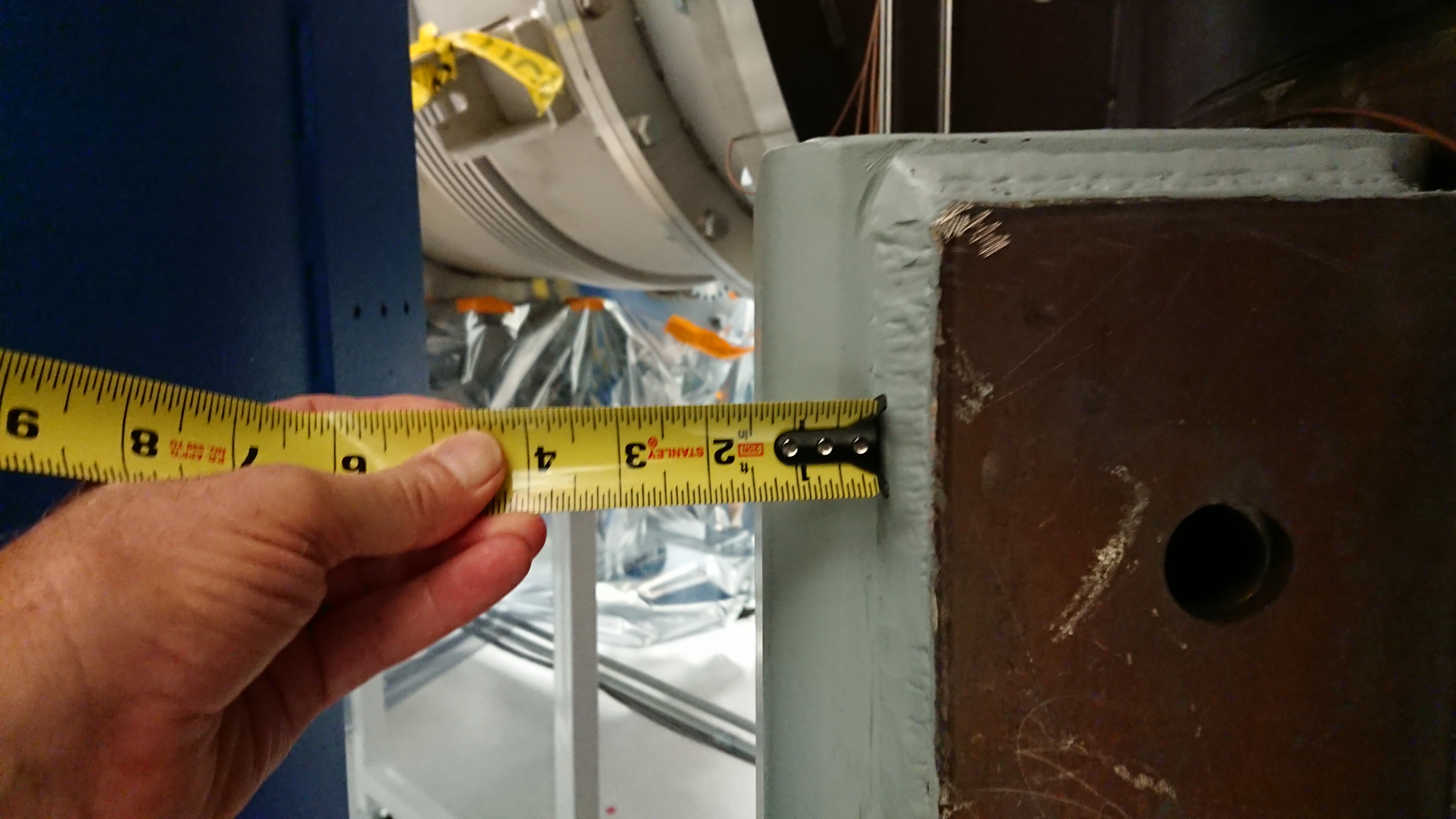
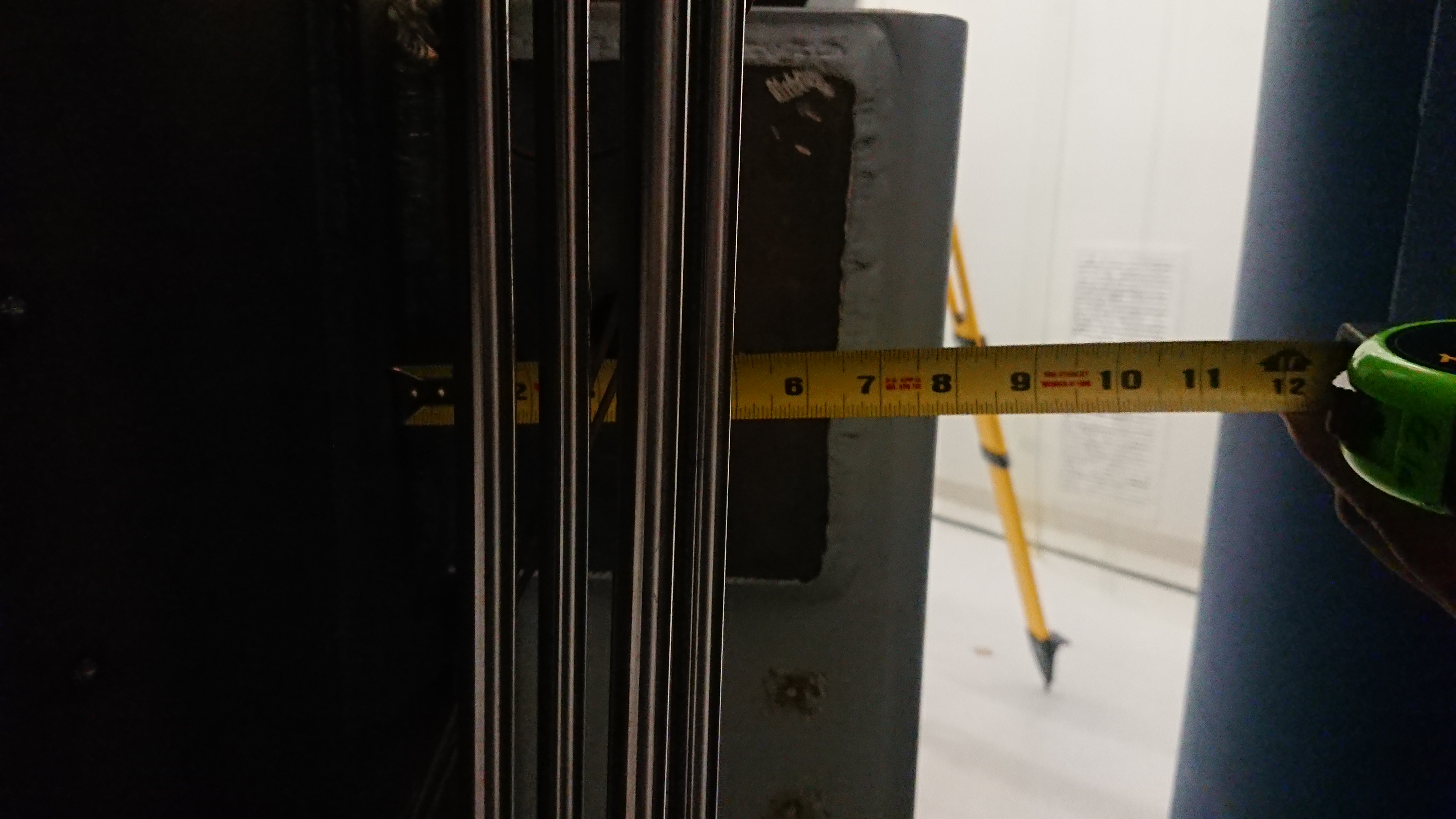
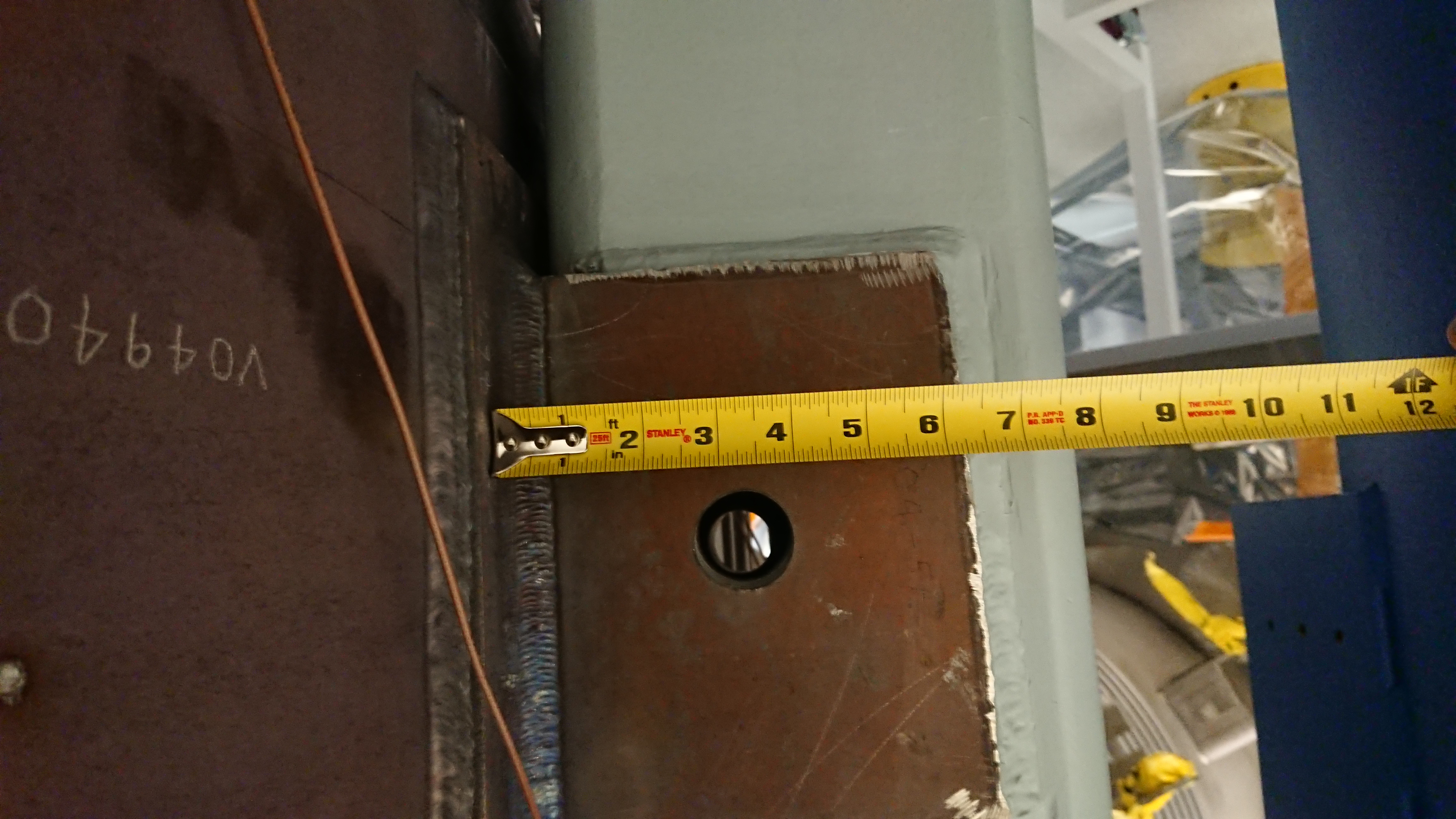
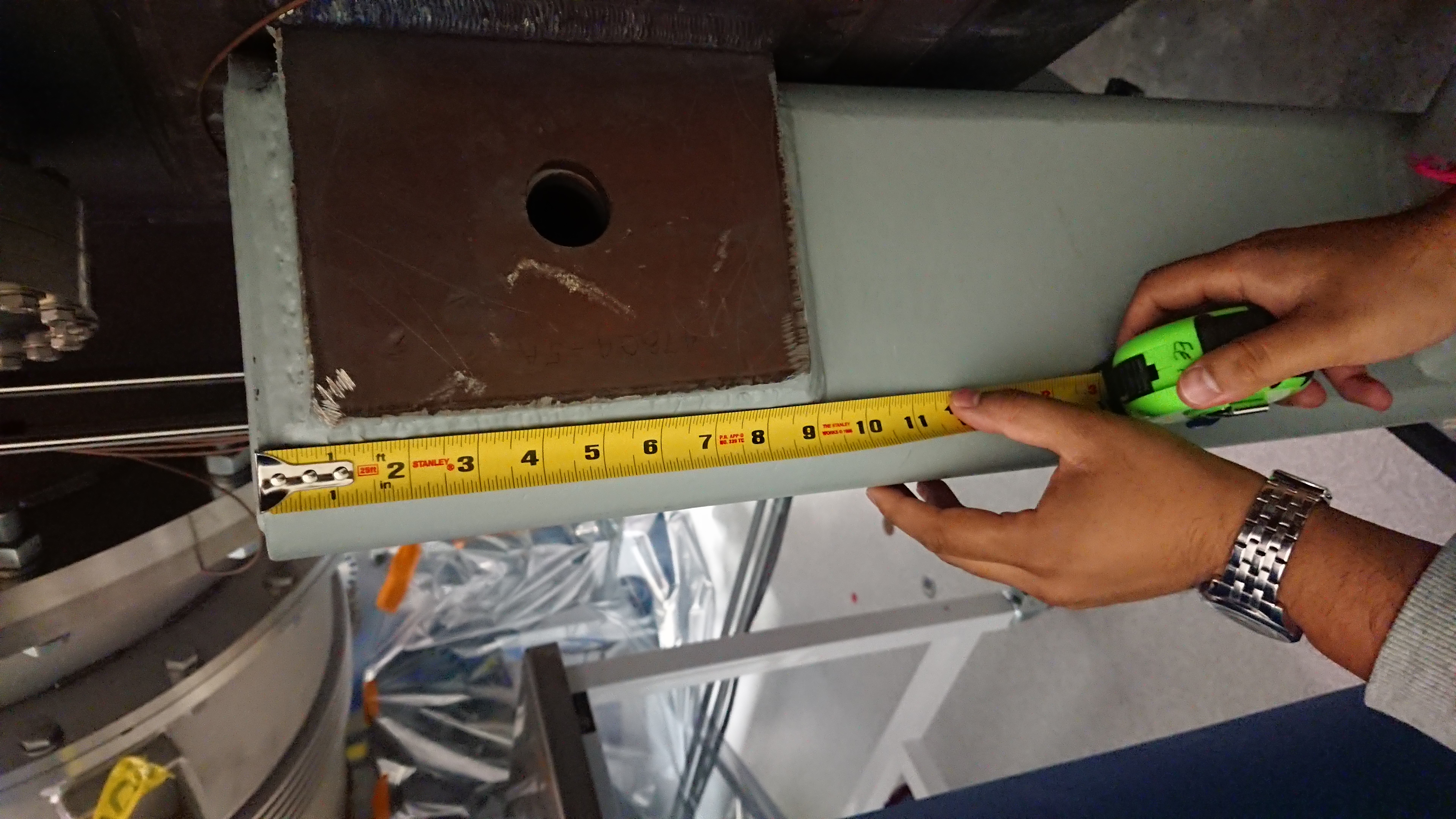
We notice that we have ~11 inches from the vacuum chamber to the HEPI pier however, there is less space than expected as there is a vacuum flange protruding from the vacuum chamber (first image - DSC_1492.JPG). Also, there is only 4.5 inches of space on the top surface of the BSC pier as a result of the vacuum flange (second image - DSC_1487.JPG). Moreover, the top surface is not as the CAD drawing depict. Instead of a flush plate with gussets in the corners, there is a square place raised up and welded (third image - DSC_1500.JPG). In addition, there are 2 extra steel plates on the sides of the BSC pier that are untreated (not painted) that are not present in the CAD drawings this extra room is required in the NCAL mount to accommodate for this (fourth image - DSC_1482.JPG) this, increasing the thickness of the side wall that we have to drill though. The weld due to the side plates will interfere with the current proposed positions for the NCAL mount (fifth image - DSC_1498.JPG and sixth image - DSC_1478.JPG).
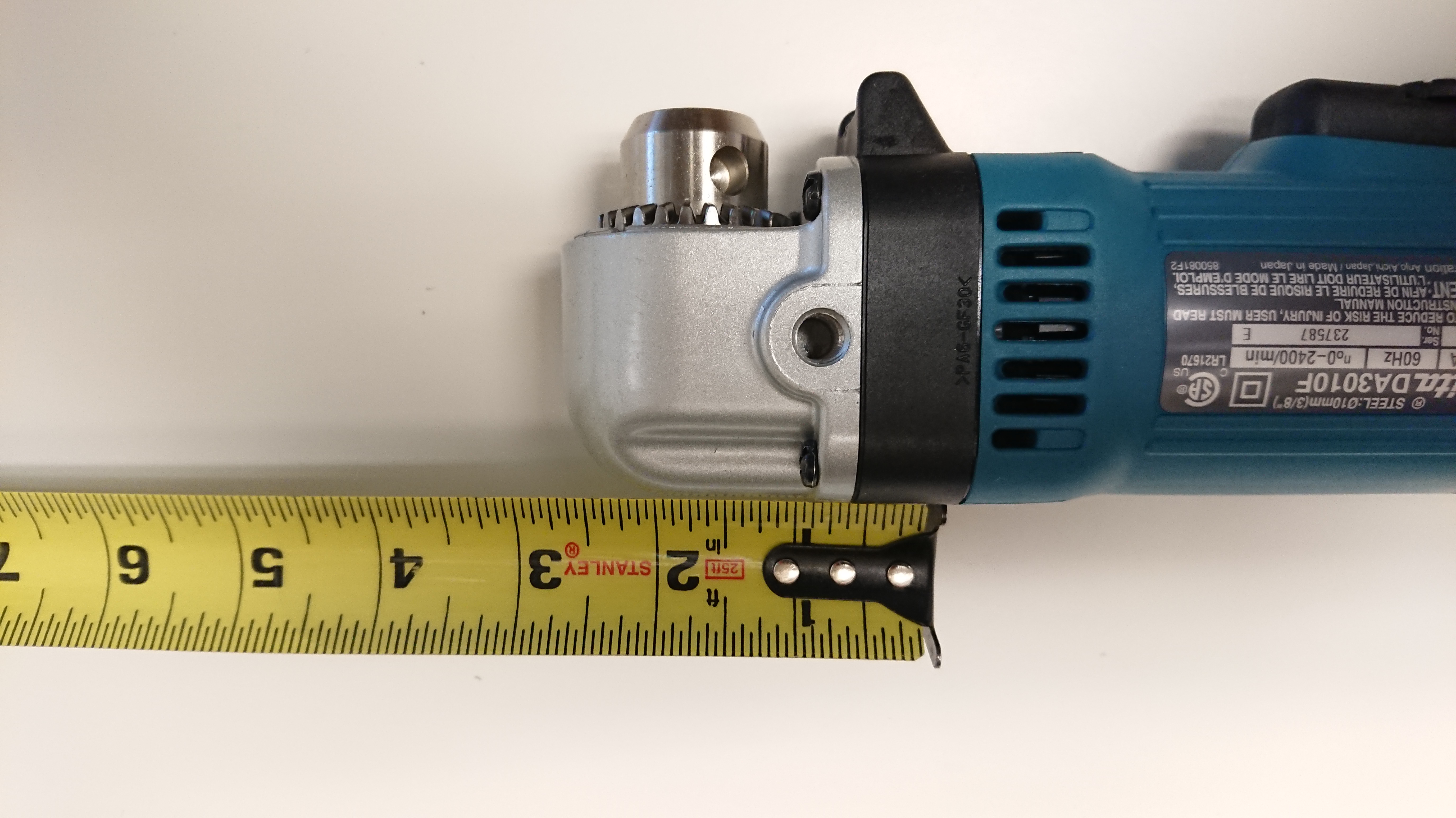
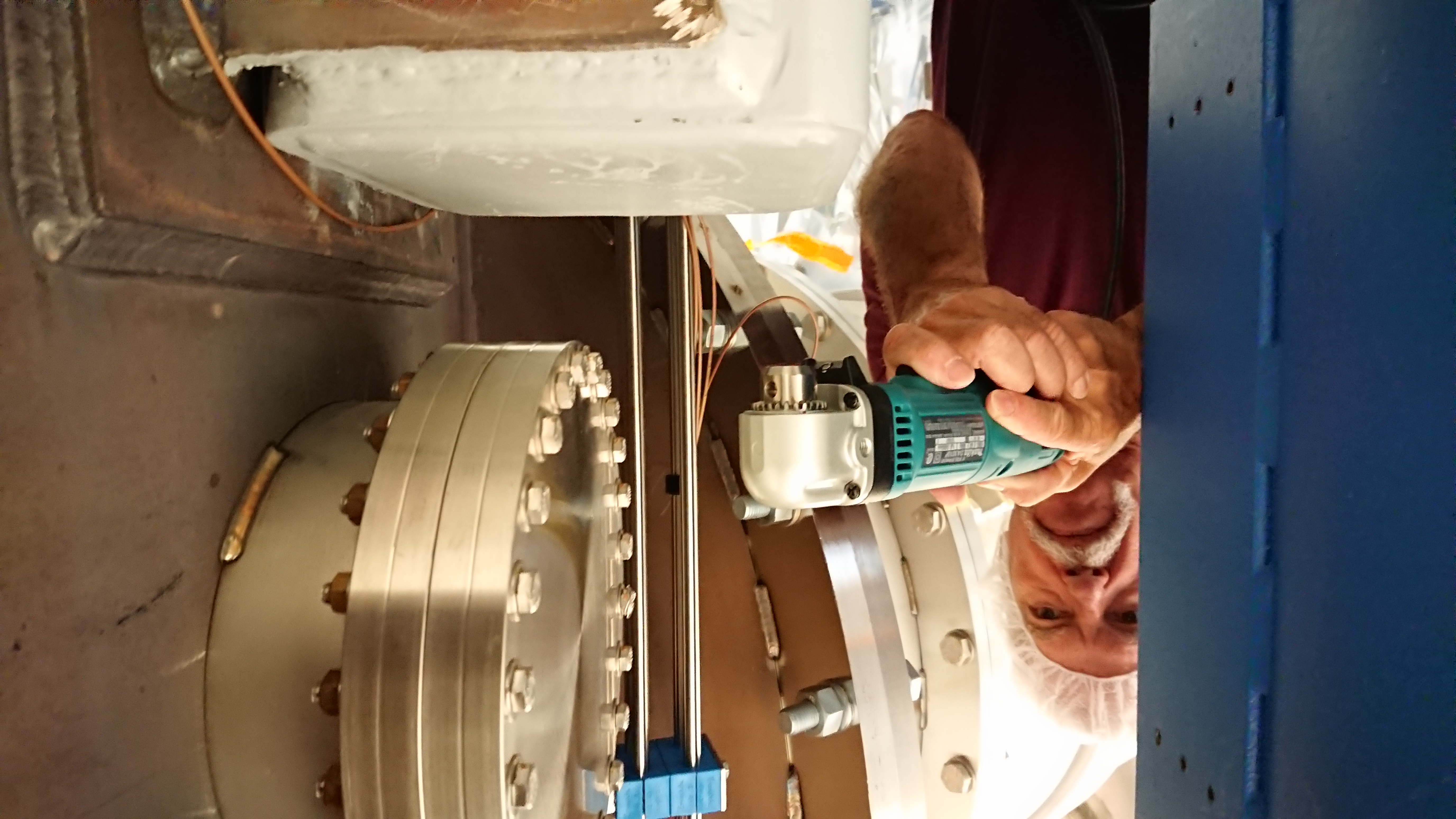
We have also found that the 90 degree angled drill we inteded to use will not be suitable for this job as it is a snug fit to get the drill into the space, without any drill bits in it. We will order a lower profile drill that will be capable of drilling into the mild steel pier.
I have attached imaged of the drill bushings, the new drill and the how space available at EX at LHO as a results of the new drill.
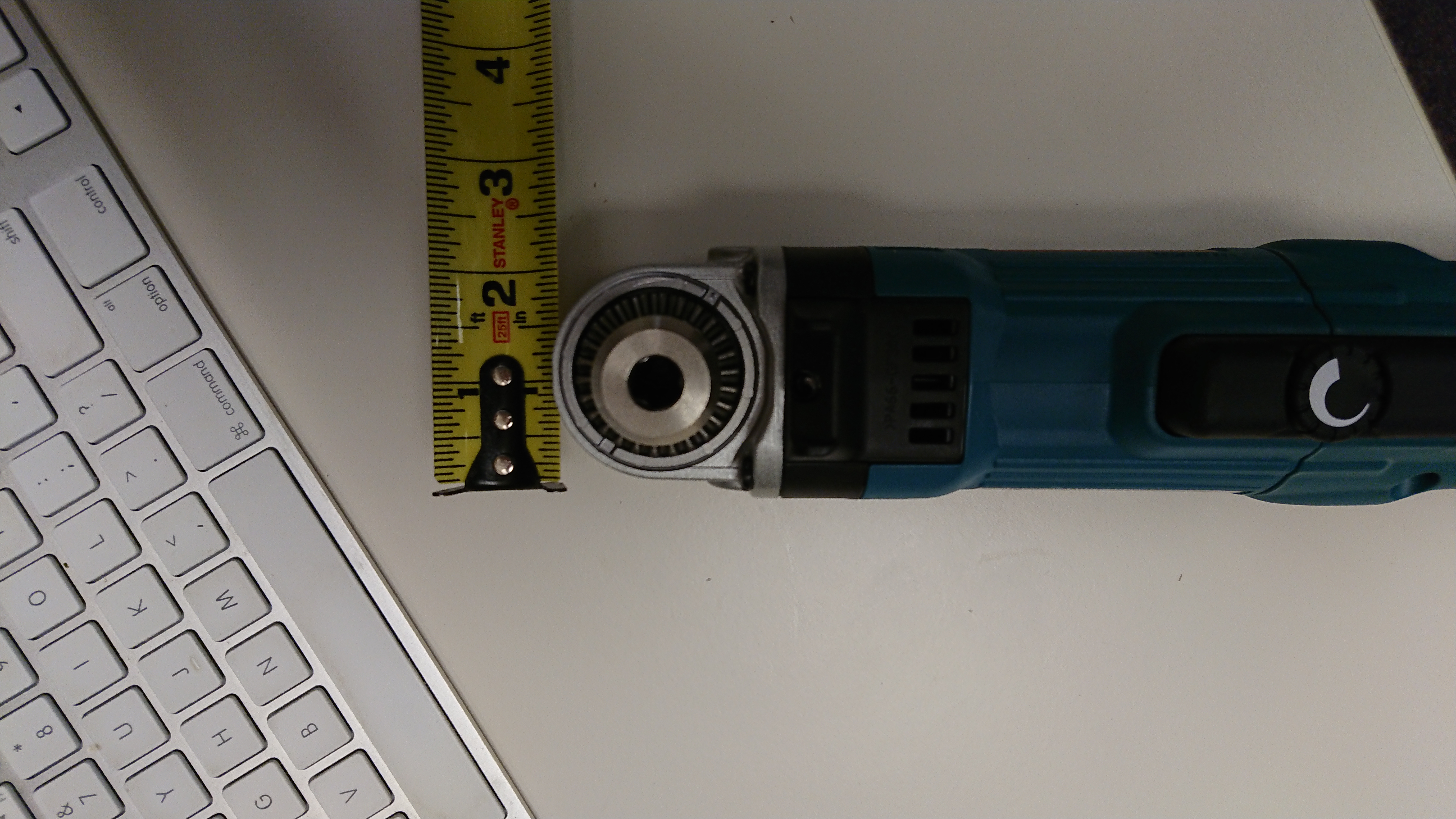
The first two images (DSC_1529.jpg and DSC_1530.jpg) show the dimension of the drill head.
The third and fourth images (DSC_1538.jpg and DSC_1539.jpg) show the clearance around the BSC pier
The fifth image (DSC_1543.jpg) shows how close one can get to the chamber flange.
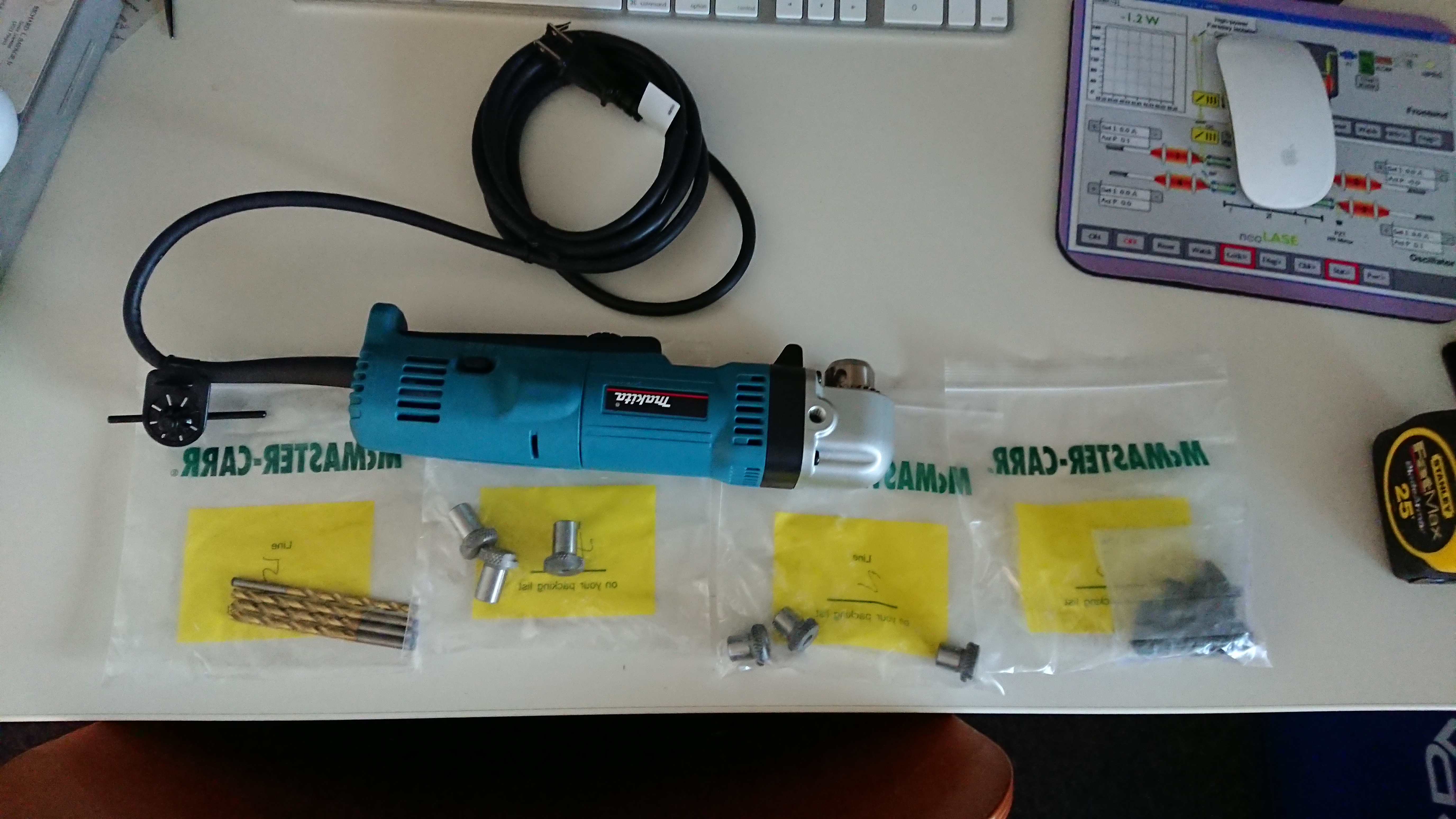
The sixth image (DSC_1545.jpg) has the parts that have been ordered (Drill, drill bushings, captive screws and the drill bits).
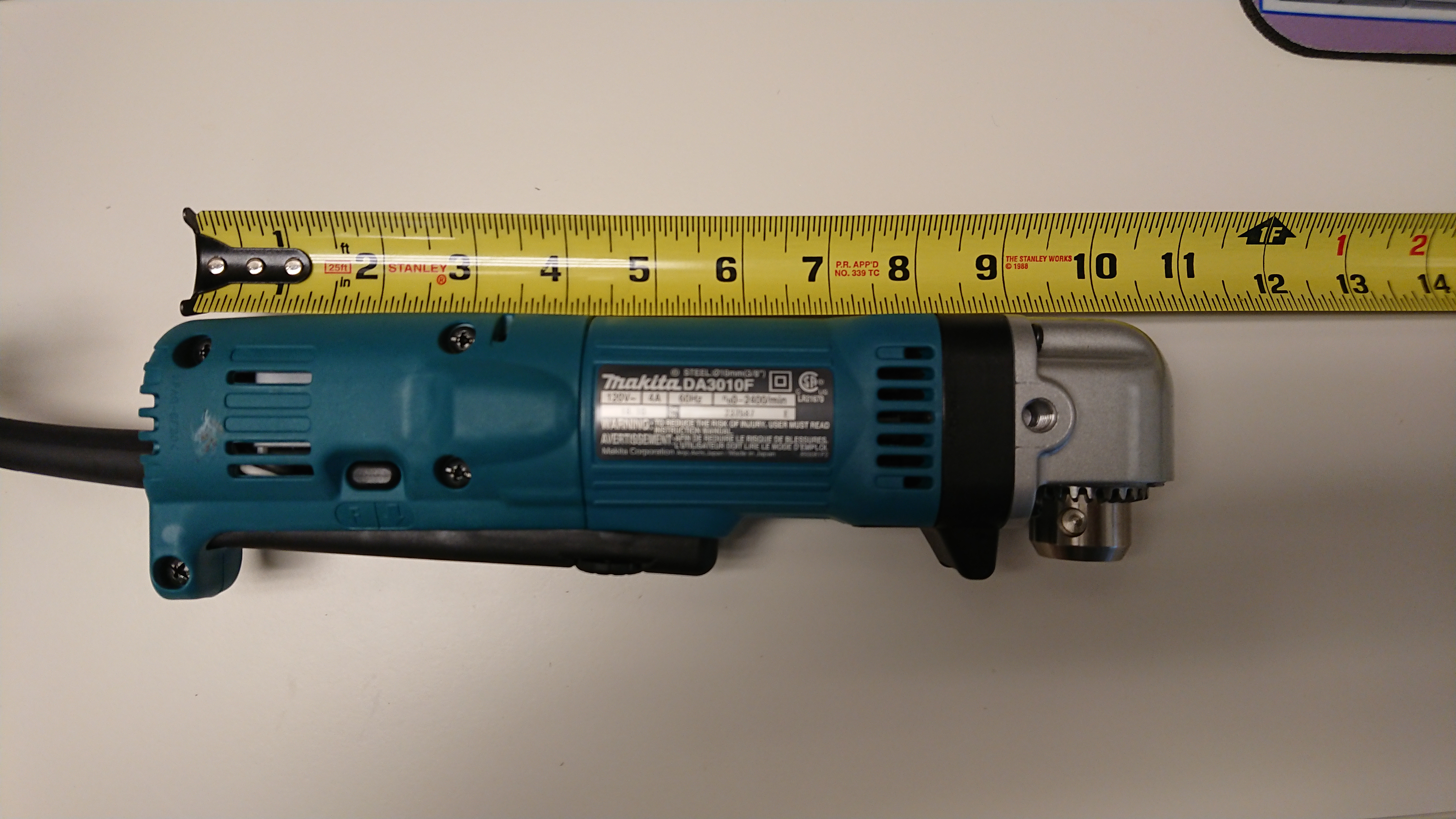
The seventh image (DSC_1525.jpg) has the full length measurement of the drill.
Consulting with Bubba, the process of drilling into the BSC pier should now be possible. We are awaiting on a final design of the jig that will help locate precisely locate the holes and ensure straight holes. The other challenge will be not breaking any taps due to the thickness of the BSC pier (especially on the sides).
[Laurance Datrier, Dripta Bhattacharjee, Timesh Mistry]
We went to the X end to take some more pictures of the BSC ISI pier. They are attached to this comment. We have the side view of the pier, measuring the span of the pier from the chamber. This should also give better measurement of the hole in the pier.
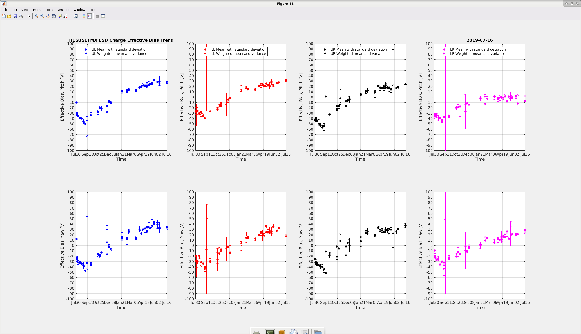
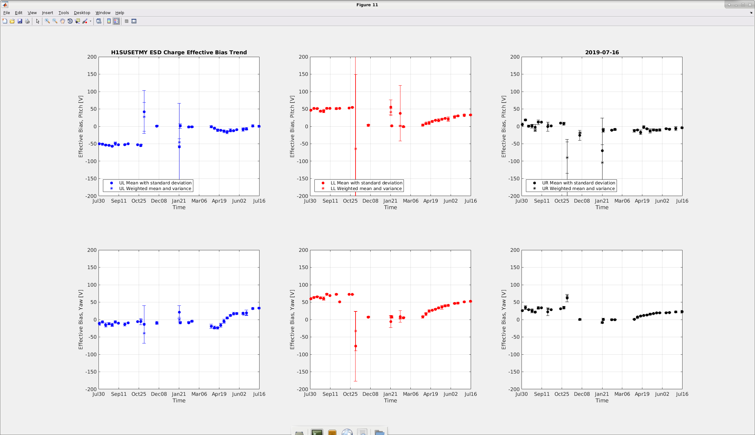
In future charge measurements for the ETMX and ETMY will be performed on a monthly basis. Since charge was not building up very quickly (which is a good thing), hence we decided to do away with weekly measurements. This will give time and window for other critical systems to be monitored during the Tuesday maintenance. For the month of July, this is the first measurement with both ETMX and ETMY results. Past few weeks we were unable to take both the measurements due to various reasons.
The results for today's measurement is attached below. For the ETMX, the previous measurements were taken few weeks ago and since then some charge has build up on the test mass mirror, although not above the threshold (i.e.. bias voltage 50V). The long term trend for the 2nd and 3rd quadrant for the pitch mode shows a jump to 30V and 25V respectively. For the yaw mode (ETMX) there is a decline (effective bias) in the 2nd quadrant (20V) and rise in the 3rd and 4th quadrant, the values remaining sub 40V and sub30V respectively.
The charge effective bias voltage for the ETMY looks fine and the long term trend also looks reasonable with no notable rise or decline.
All the values were restored after the measurements were complete and SDF difference removed for lock acquisition.
IM1 and IM2 both had alignment shifts at or over 10urad, which should be looked at and addresses today before relocking.
As part of WP8279 I have built and installed two SDF slow control monitors. h1brsexsdf - dcuid 1037 h1brseysdf - dcuid 1038 The models have been build, installed, and added to the rtsystab. Dave will install the channel list and start the models after he is given the channels to monitor.
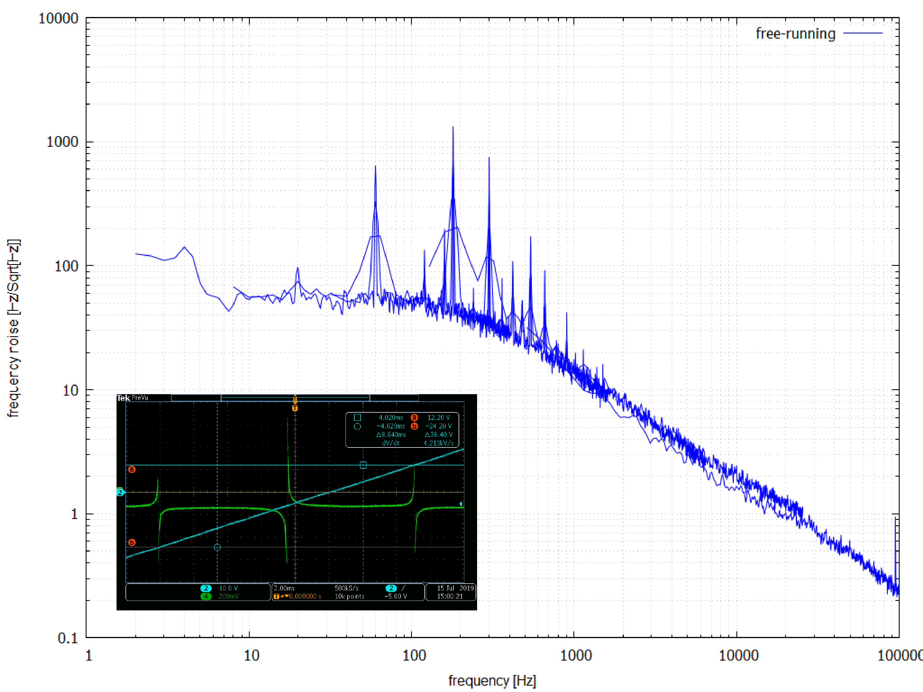
The free running frequency noise of the spare Mephisto 2000NE laser (S/N 7974) was measured.
The laser was locked to a reference cavity using an SR560 with a 0.3 Hz low pass filter
at a gain of 5. The PZT coefficient was measured to be ~1.35 MHz/V.
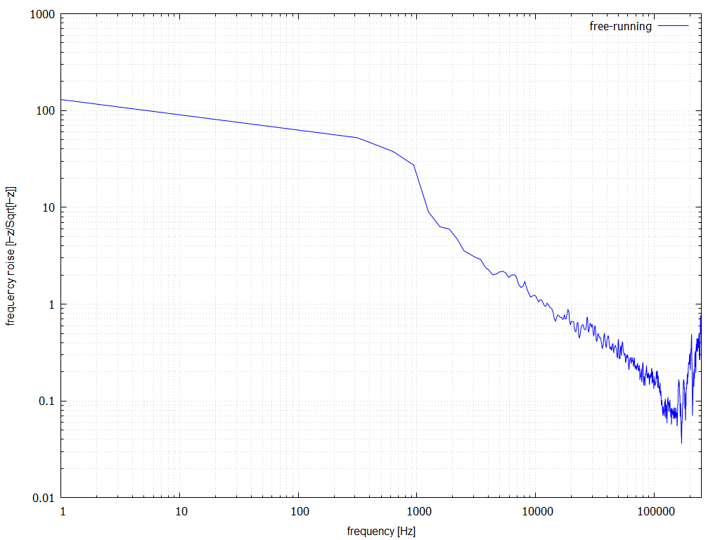
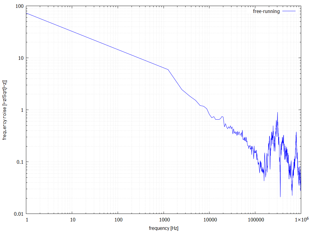
Following on from a remark Daniel made about excess noise, I repeated the measurement of the free running frequency noise of the NPRO out to 250 kHz and 1 MHz (fn2.png and fn1.png respectively). Just beyond 100 kHz we can see that the noise rises again contrary to the expectation where it continues falling off.
Noticed that the calibration for ASC-AS_C_NSUM was off by a factor of 2 indicating twice as much power as was actually there. Reduced the calibration factor by 2. The input to the NSUM block is calibrated in mW dedected by the QPD. The transmission of OM1 is 720ppm (E1100056). So, the calibration factor in W at the AS port is 1/1000*1/72e-6 = 1.39.
Added calibration factors to ASC-OMC_A_NSUM and ASC-OMC_B_NSUM. The splitter towards the ASC-OMC QPDs samples around 1.25% (E1000457). It then gets split equally between QPDs A and B. The input to the NSUM block is calibrated in mW dedected by the QPD. So the calibration factor in W at the AS portis 1/1000*2/0.0125 = 0.16.
Also changed the front-end model to use averaging rather than a straight sum for, i.e., ASC-OMC_NSUM = 1/2*(ASC-OMC_A_NSUM+ASC-OMC_B_NSUM). Same for ASC-OMC_RIN.
Jason asked if I would tweak the alignment into the reference cavity today. I did a quick tweak of the pre-modecleaner
alignment; no significant change there. A small improvement to the reference cavity transmission was made (see RCAlign.png
attachment).
I limited myself to about half an hour to complete the alignment.
TITLE: 07/16 Day Shift: 15:00-23:00 UTC (08:00-16:00 PST), all times posted in UTC
STATE of H1: Preventive Maintenance
OUTGOING OPERATOR: Cheryl
CURRENT ENVIRONMENT:
Wind: 3mph Gusts, 1mph 5min avg
Primary useism: 0.01 μm/s
Secondary useism: 0.07 μm/s
QUICK SUMMARY:
Maintenance Day Begins!!
TITLE: 07/16 Owl Shift: 07:00-15:00 UTC (00:00-08:00 PST), all times posted in UTC
STATE of H1: Preventive Maintenance
INCOMING OPERATOR: Corey
SHIFT SUMMARY: locked all shift, noise in the 38-60Hz was noisy all night, but has calmed down in the last 1 hour
LOG:
Laser Status:
Front End Power is 31.83W (should be around 30 W)
70W Output Power is 70.37W
Front End Watch is GREEN
70W Watch is GREEN
PMC:
It has been locked 13 days, 14 hr 33 minutes (should be days/weeks)
Reflected power = 10.15Watts
Transmitted power = 54.16Watts
PowerSum = 64.31Watts.
FSS:
It has been locked for 0 days 1 hr and 33 min (should be days/weeks) - this is OK, caused by lockloss of H1
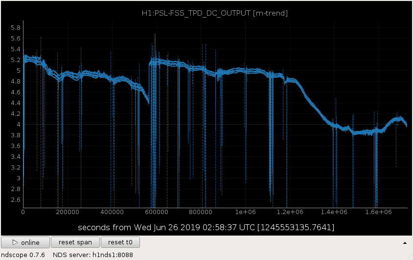
TPD[V] = 3.847V (min 0.9V)
ISS:
The diffracted power is around 2.2%
Last saturation event was 0 days 1 hours and 33 minutes ago (should be days/weeks) - this is OK, caused by lockloss of H1
Possible Issues: none, the FSS and ISS unlocked recently due to an H1 lockloss
TITLE: 07/16 Owl Shift: 07:00-15:00 UTC (00:00-08:00 PST), all times posted in UTC
STATE of H1: Observing at 111Mpc
OUTGOING OPERATOR: Ed
CURRENT ENVIRONMENT:
Wind: 12mph Gusts, 9mph 5min avg
Primary useism: 0.02 μm/s
Secondary useism: 0.06 μm/s
QUICK SUMMARY: SQZ unlocked, and relocked, and H1 is back in Observe
TITLE: 07/16 Eve Shift: 23:00-07:00 UTC (16:00-00:00 PST), all times posted in UTC
STATE of H1: Corrective Maintenance
INCOMING OPERATOR: Cheryl
SHIFT SUMMARY:
LOG:
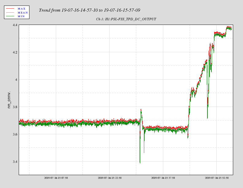
PMC TRANS on a downward trend. Also, FSS TPD voltage is down and can be seen correlating to the RH in the LASER room.(2 week plot also included)
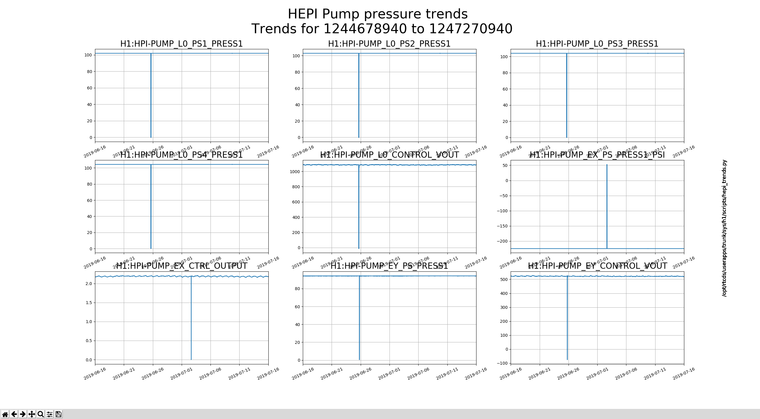
Except for EX_PS_PRESS1 being inverted from all the rest and H1 operating/observing properly, I'd say that this is a known thing and everything is ok here.
A while ago, I took some data for measuring the Q of the 10430.5 Hz mode (alog 50374). However, the RMS monitor channel for this mode wasn't working, which doesn't make a lot of sense, since it really should just be taking the rms (in the front end system) of the same signal that is being used to ring up the mode. So, I couldn't use pre-existing fitting scripts. I have not yet investigated why the RMS monitor isn't outputting sensible data.
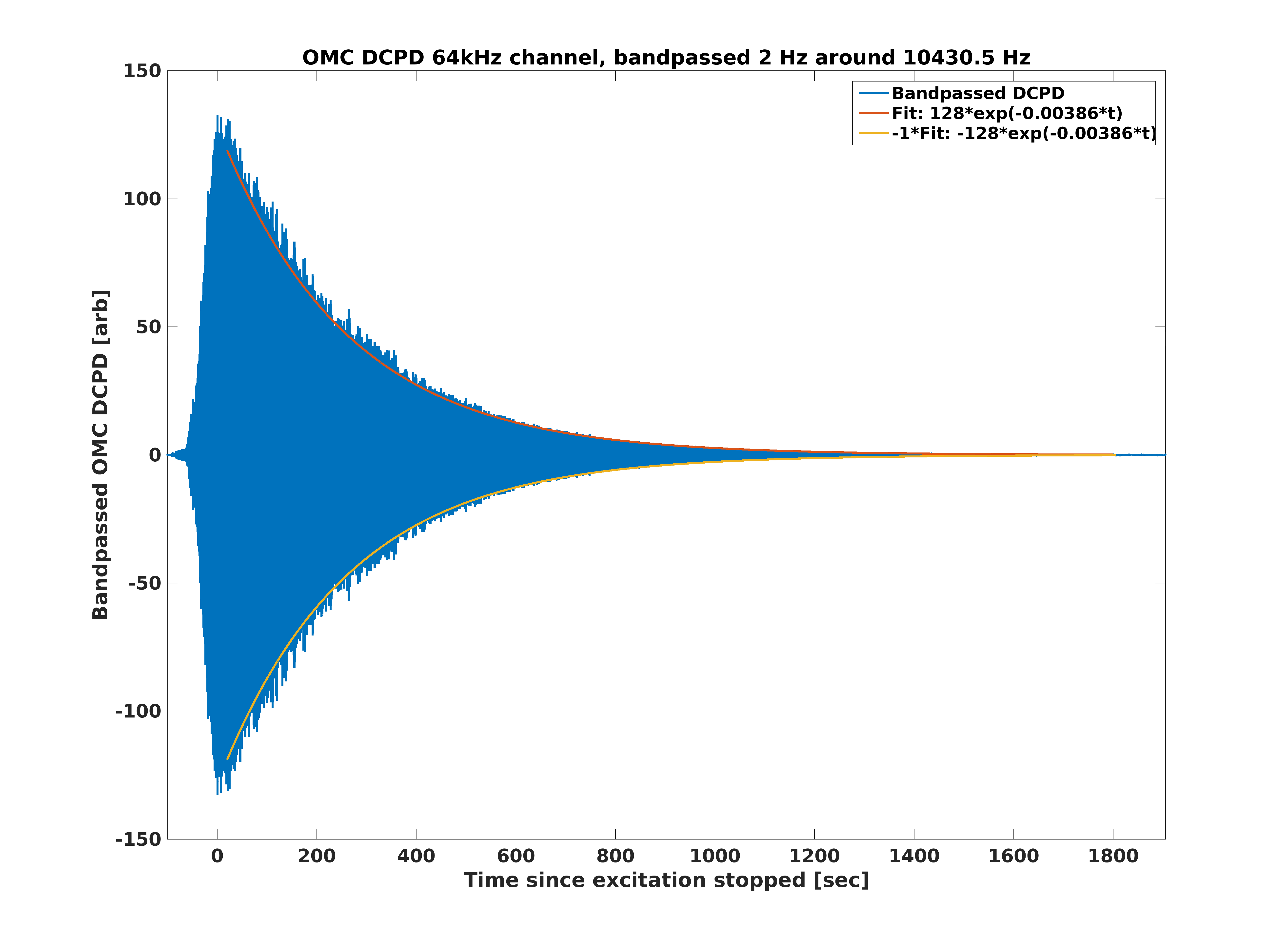
If I pull the H1:OMC-PI_DCPD_64KHZ_AHF_DQ channel and bandpass it (8th order butterworth with 2 Hz width), I clearly see the ringdown of this mode. I start the bandpassing a few hundred seconds before the beginning of the ringdown, so that I don't have to worry about transient effects of the filter. The bandpassed data is the blue trace in the attached plot.
To do the fit, I take a Hilbert Transform of the data (shifts the phase of the data by 90 degrees), so that I can get the magnitude of the ringdown envelope via: sqrt(data^2 + imag(hilbert(data))^2). I decimate this resulting envelope from 64kHz to 1024Hz to make it a less crazy number of points. I fit this envelope data (using data that starts 20 seconds after I stopped exciting up to 100 seconds before we began powering up) to a function of the form A*exp(B*t).
In the attached plot, I show the original bandpassed data, as well as the fitted envelope. Note that the result of the fit doesn't change appreciably if I restrict the data used to [20 sec, 1200 sec].
The fit results in a decay time tau of 259 seconds, which implies a Q of (pi * 10430.5Hz / tau) = 8.48e6 as the Q of the 10430.5 Hz mode.
The attached matlab .m file pulls the data, and does all of the analysis and plotting to get the tau number.
I neglected to mention that this data was taken at 2W, so as not to risk it ringing up and causing a lockloss.