This is a follow up on 90181.
Confirming that we understand the profiler data for nominal psams setting, and that the mode has changed
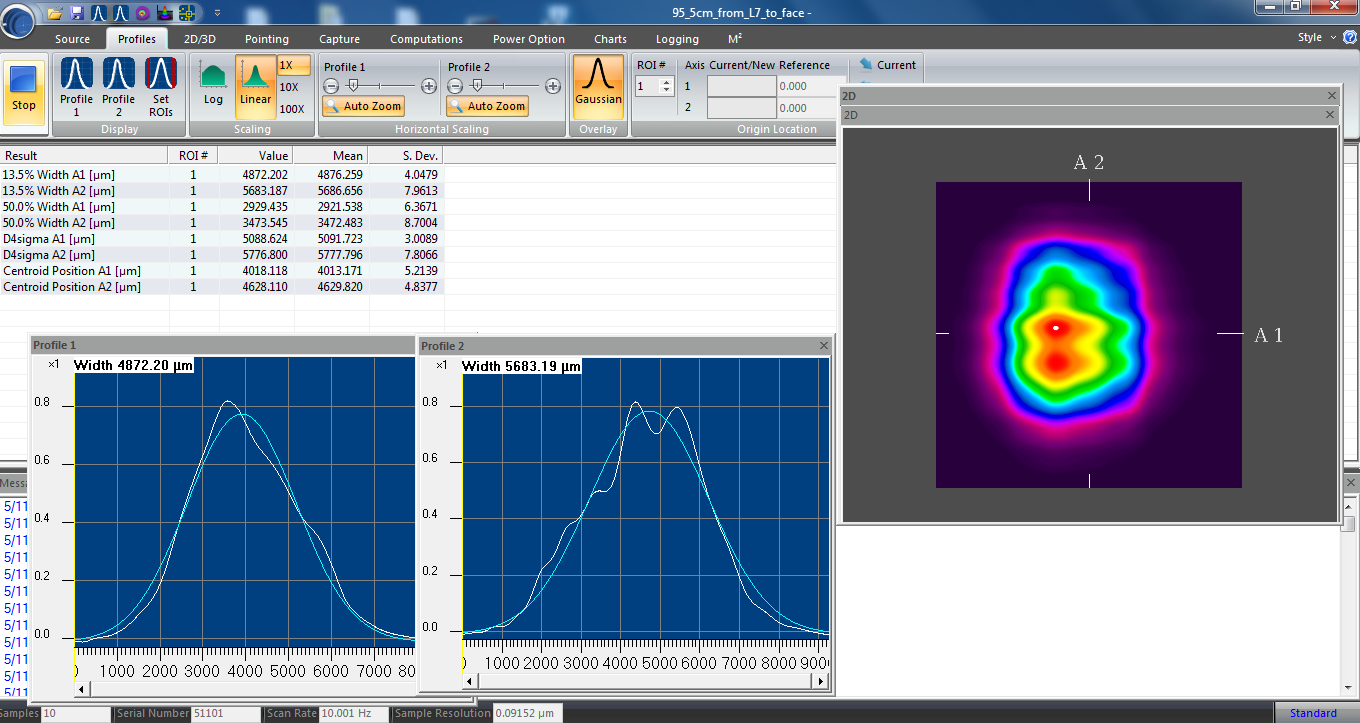
Tony, Ryan Short and I went back onto the floor the week of May 11th. We followed the alignment procedure for the M2MS profiler extension kit, which did result in different results. Because we have been confused about how to interpret the results from M2Ms, especially the "Original Waist position" Tony, Ryan and I took a scanning slit profiler out to the table and measured beam diameters at similar locations to where Leo, Camilla and Jennie measured in 85917. The scanning slit measurements are shown as dots in the attached comparison, each of them is fit by the finesse BeamParamFit shown by the solid line of the same color. Leo also did a fit to the 2025 data as reported in 86365, the finesse fits have overlaps of 98.7% and 97.5% with Leo's fits.
The M2Ms profiler reports Rayleigh length, and also "Original Waist position". From my conversations with tech support I believe that the "Original Waist position" is a distance from the reference plane as shown in this diagram, in mm (they say they will update the software to reflect that it is mm not um), where a positive number means that the waist is on the side of the reference plane closer to the source. From 90181 I believe that the reference plane is 5.678 meters from ZM5, and all these beams are converging as they leave ZM5, so the real part of q should be negative. So the real part of the q parameter is -1*(5.678-"Original beam waist position"*1e-3. ) The dashed lines in the comparison are qs from the M2Ms software, for the M2Ms overlaps with the scanning slit fit by 98.7% (vertical) and 98.9% (horizontal).
Although the different fitting and measurement types don't exactly agree with each other, the mode is clearly different after the OPO swap, the overlap of the beam width measurements now vs Summer 2025 is 87% for vertical and 85% for horizontal. In summer 2025 the overlap of the horiztonal mode with the verical mode was 98%, now it is 99.5%.
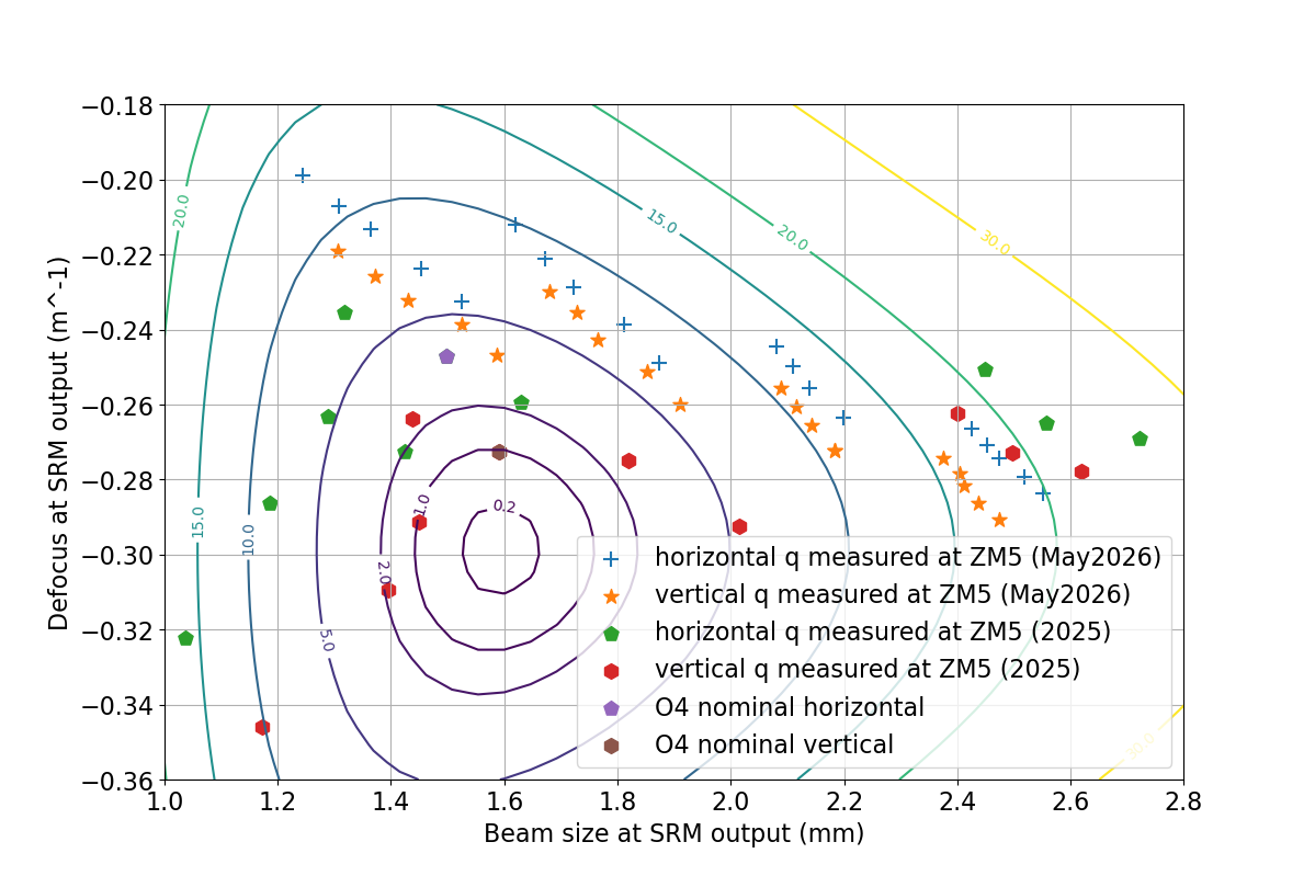
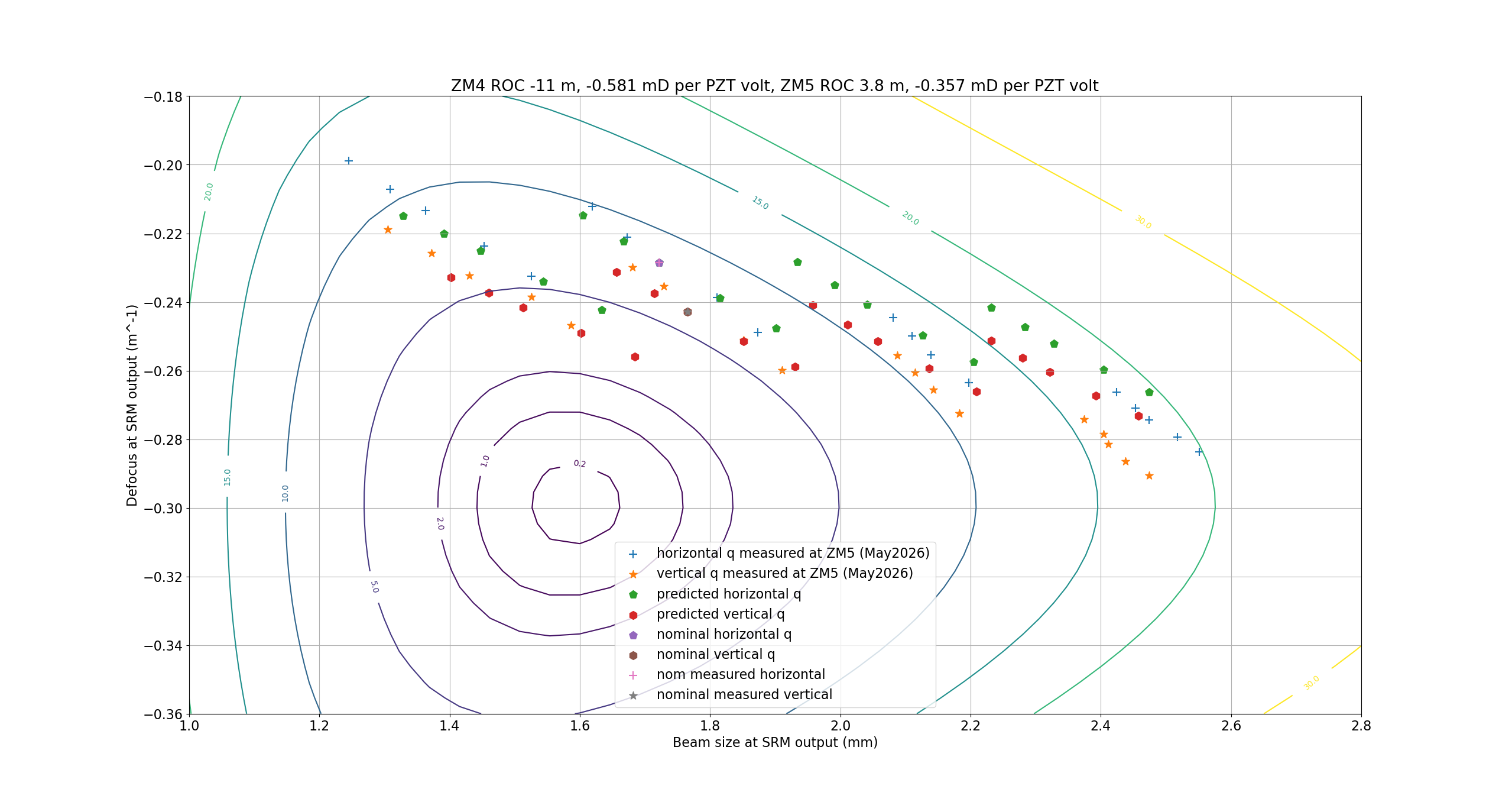
Sw plot for various psams settingsThis plot shows the measured beam parameters, both from this recent data set and from Leo's fits in 86365,propagated to SRM, with contours showing constant mode matching to the OMC for reference. This can be compared to plots that Evan Hall has made in G2600435. In O4, this confirms that we our choice for a nominal psams setting did bring us as close to good mode matching to the OMC with the psams that we had, but that we couldn't access the best mode matching parts of the space. This also confirms that the astimgatism of the squeezer beam would have limited our mode matching if we had been able to move the psams to bring the beam closer to the OMC mode.
Guess and check for psams actuation strength
Using this May 2026 set of q measurements, I've attempted to check the actuation strength of ZM4+ ZM5 psams. Since we don't have a measurement of the q before ZM4, we don't actually have information in this dataset about the curvature of ZM4 (we can't distinguish between the curvature of the beam incident on ZM4 with the curvature of ZM4). Alog 90218 summarizes what we expect for the ROC of the psams with 0V applied to the PZT based on the preload that was applied. I've taken a set of guesses for the ROCs at nominal psams settings, and mD/V for each psams, and used the measured horizontal and vertical q for the nominal psams settings to propagate back to a q incident on ZM4. Then I propagated that forward for each different psams voltage, to predict the qs and compare to the measured qs in the attached plot. We have no information about the ZM4 ROC here, since we don't know the curvature of the beam incident on ZM4, so that parameter doesn't matter. There is also a degeneracy between the nominal ZM5 ROC and the actuation strength of ZM4, they both change the spacing between the group of 5 measurements taken at different ZM4 voltages.
We can find the nominal psams actuation strengths from E2100288,(we have ZM4 SN1 and ZM5 SN4 at H1), although those measurements were from before the pre-load was changed Camille tells me they should be about the same. I cannot get a reasonable match to the measured data without reducing the actuation strength of ZM5 to about half of what it should be. For ZM5 ROC, we can make an estimate based on 90186 and the nominal -0.58mD/V pzt reponse that the nominal ROC should be around 3meters, this doesn't seem to give us a good match to the measured q parameters.
This is a follow up on 90181.
Confirming that we understand the profiler data for nominal psams setting, and that the mode has changed
Tony, Ryan Short and I went back onto the floor the week of May 11th. We followed the alignment procedure for the M2MS profiler extension kit, which did result in different results. Because we have been confused about how to interpret the results from M2Ms, especially the "Original Waist position" Tony, Ryan and I took a scanning slit profiler out to the table and measured beam diameters at similar locations to where Leo, Camilla and Jennie measured in 85917. The scanning slit measurements are shown as dots in the attached comparison, each of them is fit by the finesse BeamParamFit shown by the solid line of the same color. Leo also did a fit to the 2025 data as reported in 86365, the finesse fits have overlaps of 98.7% and 97.5% with Leo's fits.
The M2Ms profiler reports Rayleigh length, and also "Original Waist position". From my conversations with tech support I believe that the "Original Waist position" is a distance from the reference plane as shown in this diagram, in mm (they say they will update the software to reflect that it is mm not um), where a positive number means that the waist is on the side of the reference plane closer to the source. From 90181 I believe that the reference plane is 5.678 meters from ZM5, and all these beams are converging as they leave ZM5, so the real part of q should be negative. So the real part of the q parameter is -1*(5.678-"Original beam waist position"*1e-3. ) The dashed lines in the comparison are qs from the M2Ms software, for the M2Ms overlaps with the scanning slit fit by 98.7% (vertical) and 98.9% (horizontal).
Although the different fitting and measurement types don't exactly agree with each other, the mode is clearly different after the OPO swap, the overlap of the beam width measurements now vs Summer 2025 is 87% for vertical and 85% for horizontal. In summer 2025 the overlap of the horiztonal mode with the verical mode was 98%, now it is 99.5%.
Sw plot for various psams settingsThis plot shows the measured beam parameters, both from this recent data set and from Leo's fits in 86365,propagated to SRM, with contours showing constant mode matching to the OMC for reference. This can be compared to plots that Evan Hall has made in G2600435. In O4, this confirms that we our choice for a nominal psams setting did bring us as close to good mode matching to the OMC with the psams that we had, but that we couldn't access the best mode matching parts of the space. This also confirms that the astimgatism of the squeezer beam would have limited our mode matching if we had been able to move the psams to bring the beam closer to the OMC mode.
Guess and check for psams actuation strength
Using this May 2026 set of q measurements, I've attempted to check the actuation strength of ZM4+ ZM5 psams. Since we don't have a measurement of the q before ZM4, we don't actually have information in this dataset about the curvature of ZM4 (we can't distinguish between the curvature of the beam incident on ZM4 with the curvature of ZM4). Alog 90218 summarizes what we expect for the ROC of the psams with 0V applied to the PZT based on the preload that was applied. I've taken a set of guesses for the ROCs at nominal psams settings, and mD/V for each psams, and used the measured horizontal and vertical q for the nominal psams settings to propagate back to a q incident on ZM4. Then I propagated that forward for each different psams voltage, to predict the qs and compare to the measured qs in the attached plot. We have no information about the ZM4 ROC here, since we don't know the curvature of the beam incident on ZM4, so that parameter doesn't matter. There is also a degeneracy between the nominal ZM5 ROC and the actuation strength of ZM4, they both change the spacing between the group of 5 measurements taken at different ZM4 voltages.
We can find the nominal psams actuation strengths from E2100288,(we have ZM4 SN1 and ZM5 SN4 at H1), although those measurements were from before the pre-load was changed Camille tells me they should be about the same. I cannot get a reasonable match to the measured data without reducing the actuation strength of ZM5 to about half of what it should be. For ZM5 ROC, we can make an estimate based on 90186 and the nominal -0.58mD/V pzt reponse that the nominal ROC should be around 3 meters, this doesn't seem to give us a good match to the measured q parameters.
The scripts used to make these plots are available here: plot_dataset_May2026.py and compare_summer_2025_to_may2026.py I've also uploaded the conversation with Thorlabs tech support T2600231