Topped off crystal chiller with 275mL of water (last fill was 3-weeks ago on 6/12/19). Diode chiller and filters were OK.
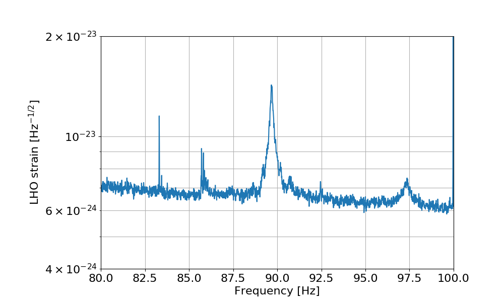
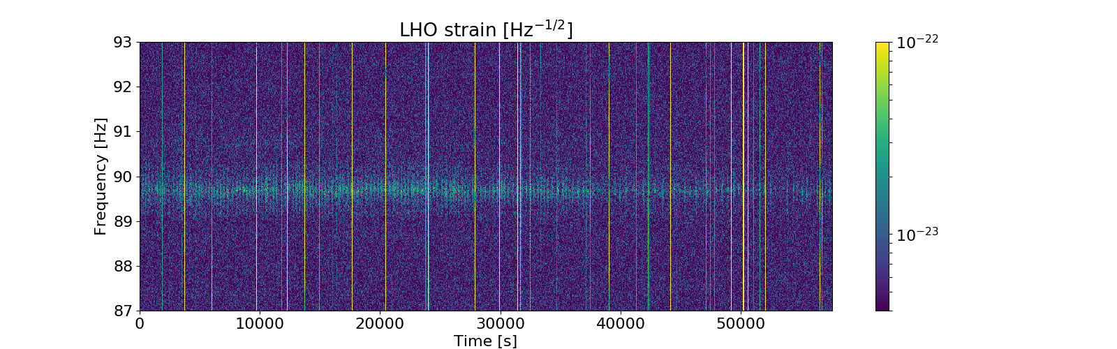
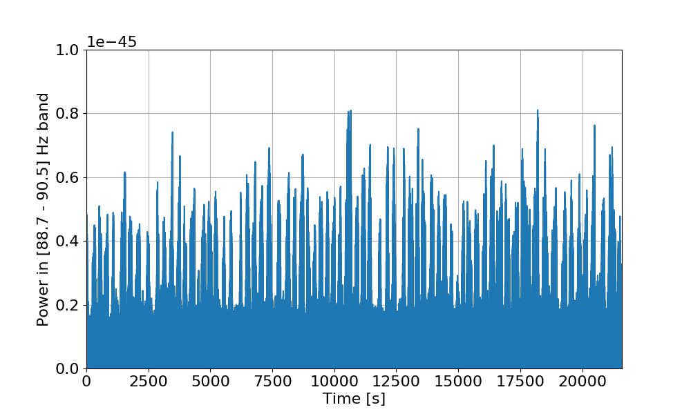
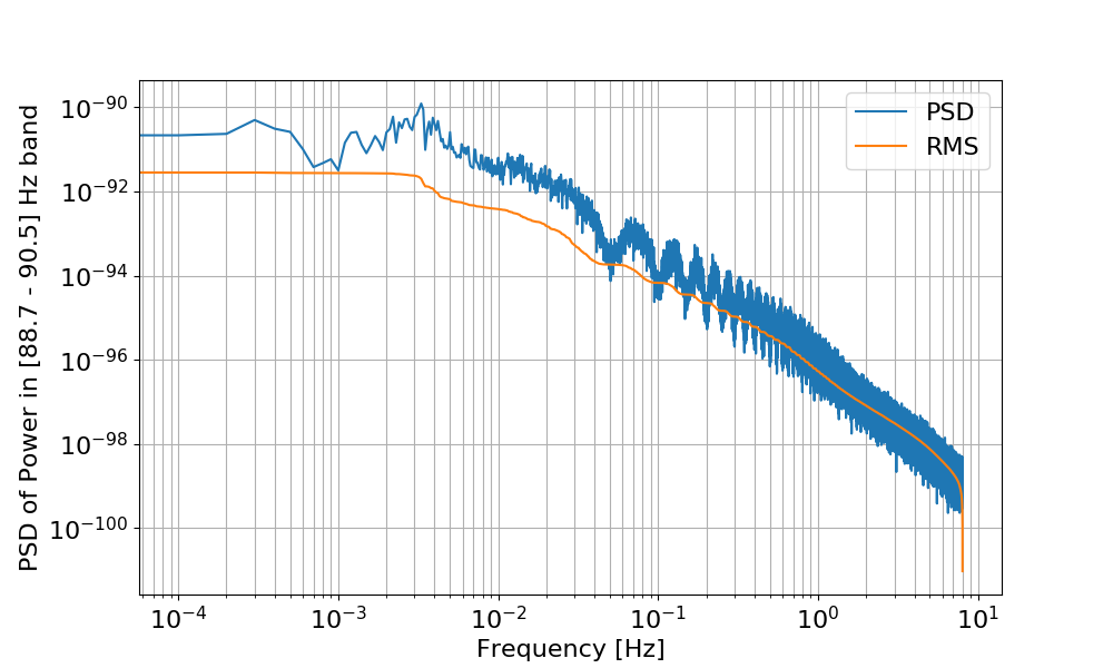
The bump at ~90 Hz is breathing with a very prominent periodicity of about 3 mHz. Any idea where this oscillation could come from?
The first plot shows a zoom around 90 Hz, where the bump is quite clear.
The second plot is a spectrogram of the same 16 hours of data (from 1245974418), showing the non-stationarity of the bump.
The third plot shows the band-limited RMS computed on the bump (between 88.7 and 90.5 Hz), with large glitches removed. The periodic "on and off" behavior is quite evident.
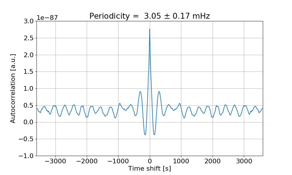
The fourth plot shows the PSD of the time series of the BLRMS, and the integrated RMS. There is a peak at 3 mHz. This is even more visible if one computes the autocorrelation of the BLRMS series: the fifth plot shows that the autocorrelation has a clear signature of a 3 mHz periodicity.
I decided to run an initial alignment because I could not keep the green arms locked, despite flashes > 1. I requested INITIAL_ALIGNMENT from ISC_LOCK and the entire process finished without me having to intervene. Yesterday, I had to touch green arms slightly, but this was the first time I didn't have to do anything.
The entire alignment took 22 min. (1523 - 1545 UTC)
TITLE: 07/03 Day Shift: 15:00-23:00 UTC (08:00-16:00 PST), all times posted in UTC
STATE of H1: Lock Acquisition
OUTGOING OPERATOR: Travis
CURRENT ENVIRONMENT:
Wind: 10mph Gusts, 7mph 5min avg
Primary useism: 0.03 μm/s
Secondary useism: 0.09 μm/s
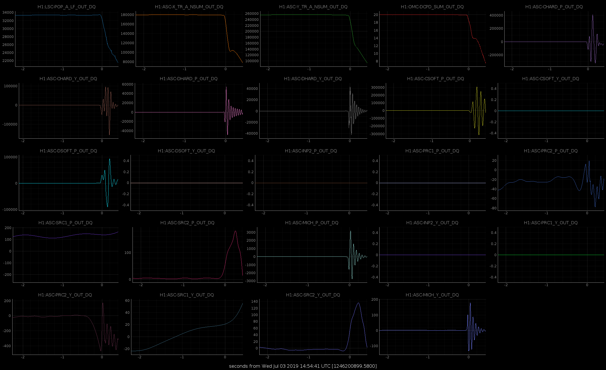
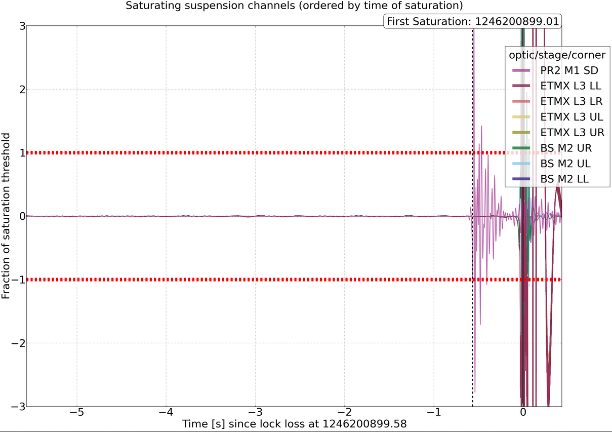
QUICK SUMMARY: Lock loss just as I arrived. No obvious reasons found yet.
TITLE: 07/03 Owl Shift: 07:00-15:00 UTC (00:00-08:00 PST), all times posted in UTC
STATE of H1: Observing at 116Mpc
INCOMING OPERATOR: TJ
SHIFT SUMMARY: Another quiet shift. One GRB alert. Lockloss at the very end of shift.
LOG: Previous aLogs.
Seemingly spontaneous lockloss. Environment is calm. No indication of cause. Sorry TJ!
GraceDB UID E337636.
Fermi alert trigger num 583854113.
Trigger duration of 0.016 second.
Beginning stand down time.
I just realized that the Observatory Mode had not been changed since Jim relocked before the start of my shift. I changed it to Observing at 8:48 UTC, but it should have been changed closer to 6:22 UTC. Can this be retroactively changed for time reporting?
Thanks for noting, Travis. I am not sure we can change this (or if we can, it is not trivial). So the times you note will be helpful for analysis/notes later.
TITLE: 07/03 Owl Shift: 07:00-15:00 UTC (00:00-08:00 PST), all times posted in UTC
STATE of H1: Lock Acquisition
OUTGOING OPERATOR: Jim
CURRENT ENVIRONMENT:
Wind: 8mph Gusts, 7mph 5min avg
Primary useism: 0.02 μm/s
Secondary useism: 0.07 μm/s
QUICK SUMMARY: Lock is ~1 hour old. Range is 116 MPc. Nothing out of the ordinary to report.
Can't include the normal header because Chrome isn't playing with the HTML editor for the alog. Travis is taking over, we're observing, range is normal. 2:30 Observing after struggling with wind and doing an initial alignment 4:53 A 5.3 eq in north Alaska breaks the lock I didn't get a chance to change SEI states 6:30 I noticed asc and a couple other signals were doing decidedly earthquake like things, so I switch to the EQ state. This was a 4.3 in Mexico that was barely off the board on the sei eq plot, and ended up not a big deal, but hard to know beforehand. 6:41 SEI back to windy
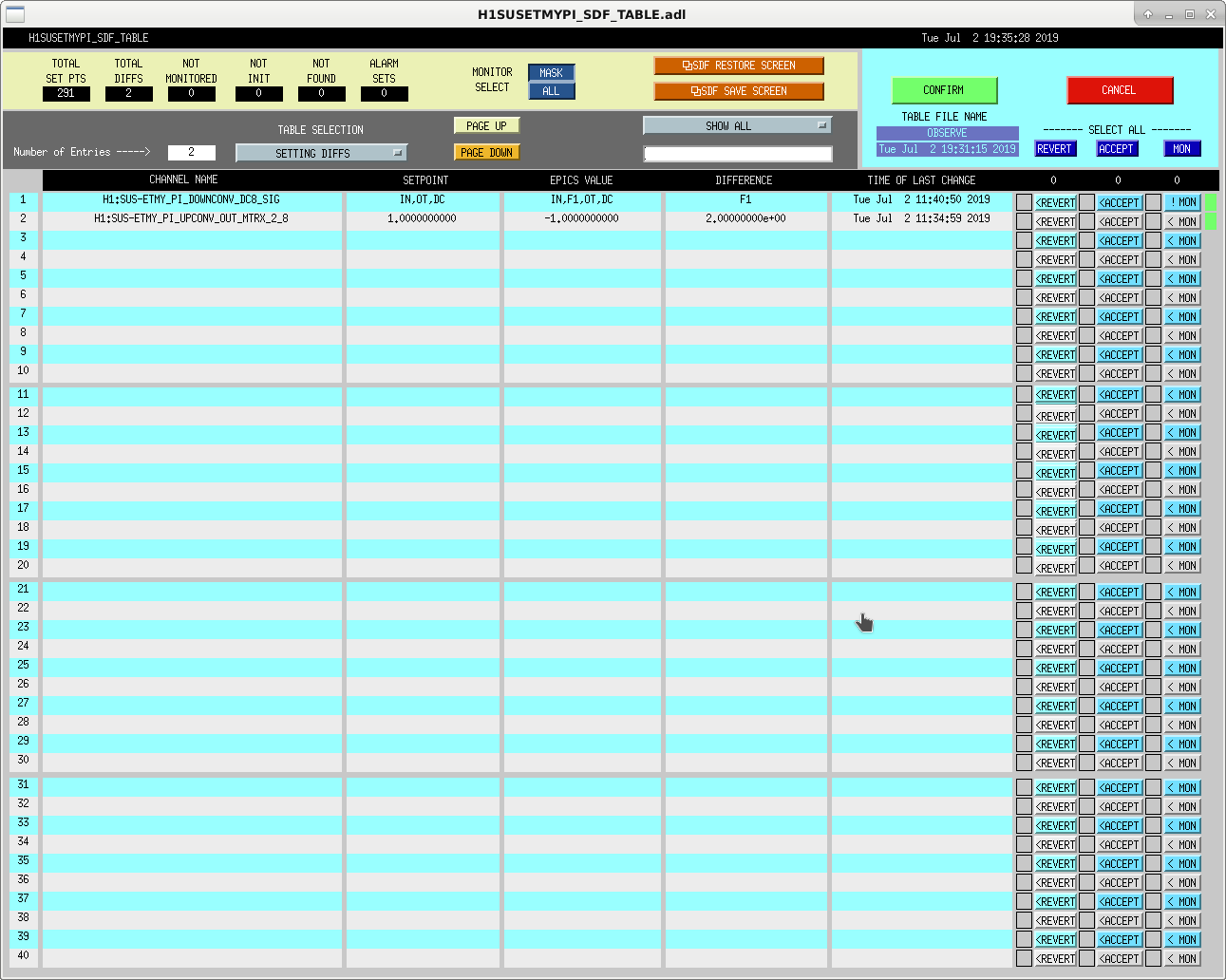
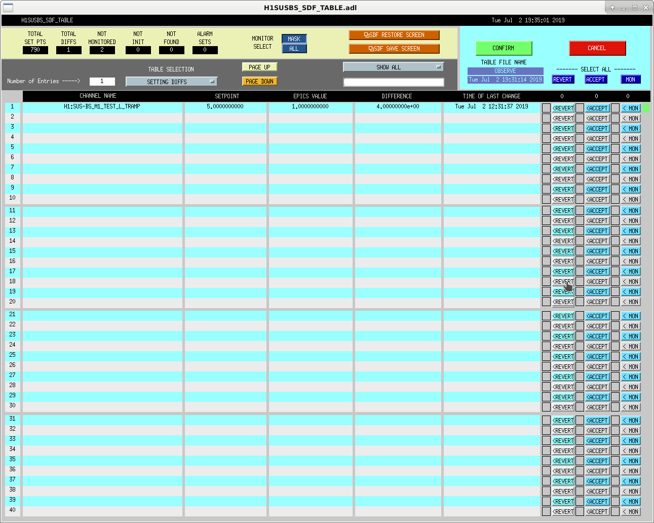
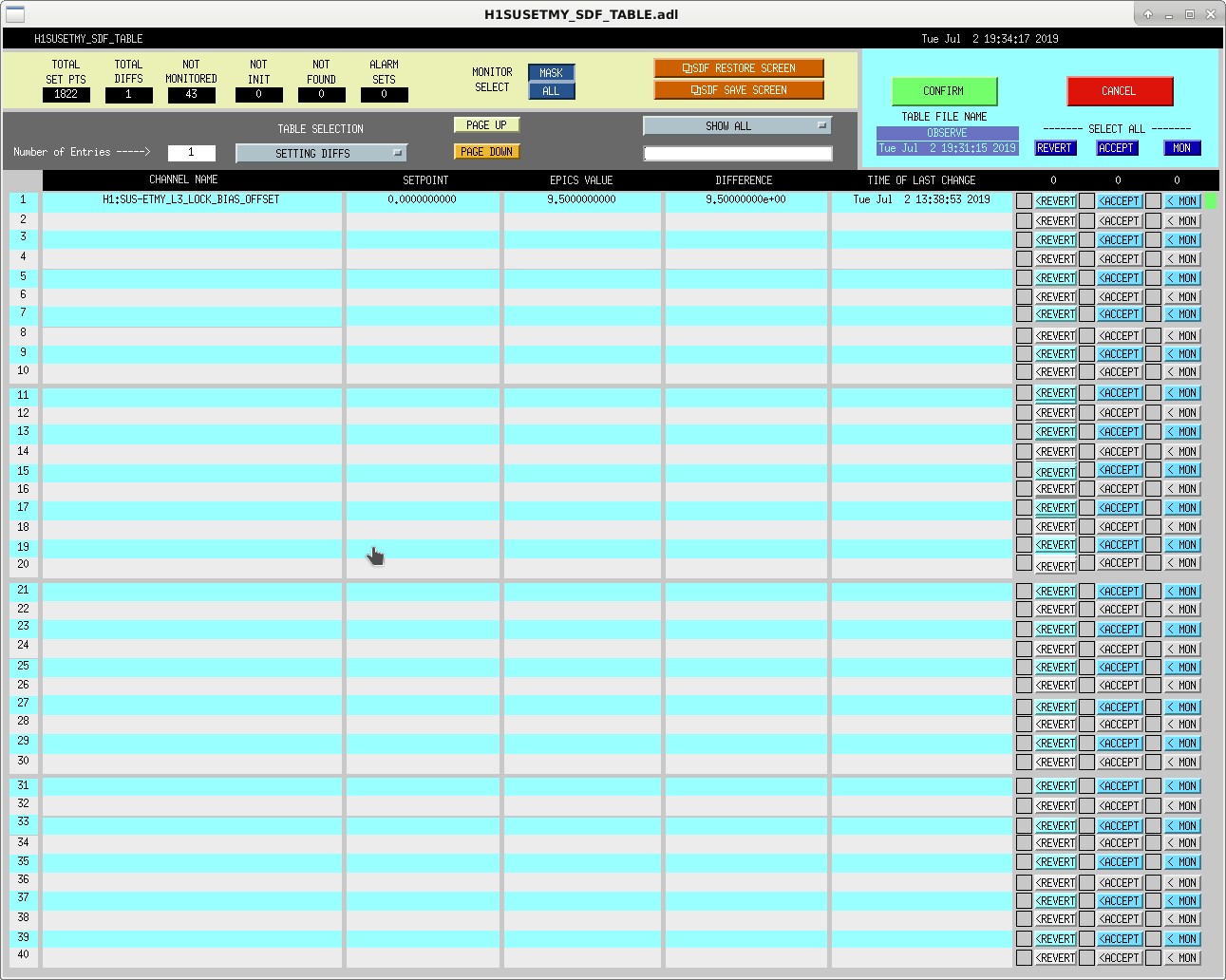
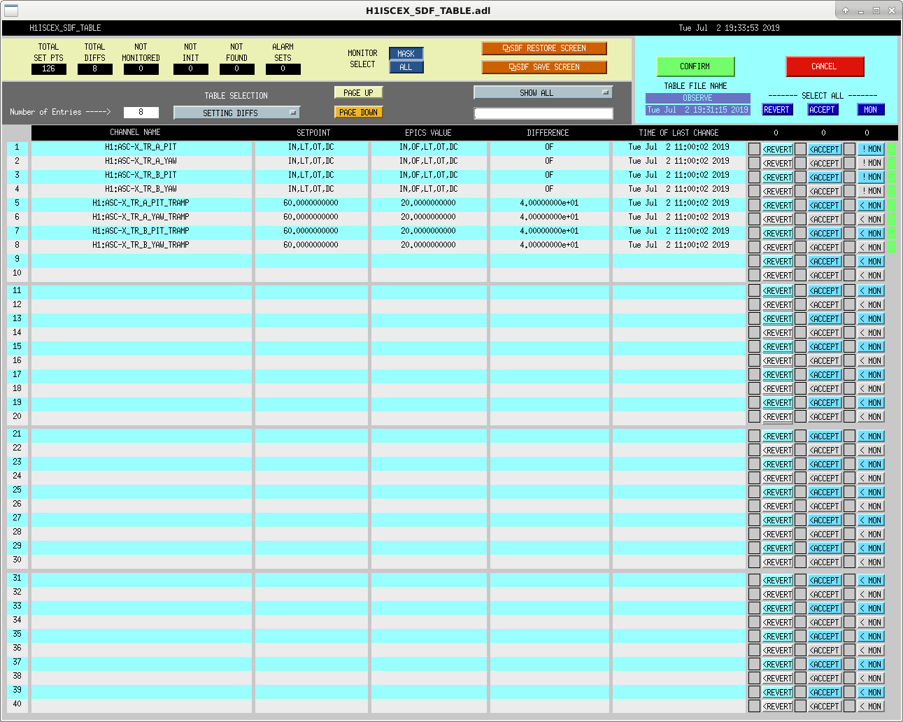
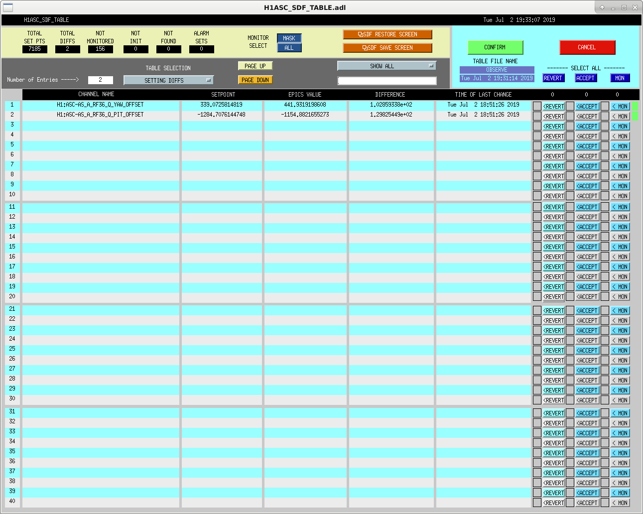
Finally back to low noise after struggles with wind, ALS and ASC. Bunch of SDF diffs, some of which I think are left over from the commissioning work earlier?
Shoot, sorry.
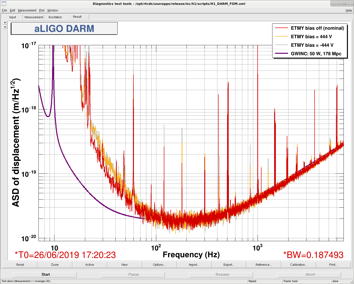
I was wrong on the ETMY ESD bias - Jim checked and found that there was no value in the offset, just the button was on. So, no impact at all on DARM.
Mostly a note to self for tomorrow:
The green WFS offloading during the main lock acquisition sequence seems to be happening too soon, before the DOF outputs have converged. Need to ensure both error and control signals have converged before starting the offload sequence, if we want the mirrors to be at the best position for next acquisition.
7/1/2019
Richard M., Filiberto C., Kyle R.
Richard M. and Filiberto C. lifted the 208VAC 3ph wiring that had supplied the iLIGO MTP Turbo Pump. This alllowed me to fully remove the conduit stub+unistrut and Hubble connector from the VEA floor. Additionally, I removed the MTP - QDP80 signal cable junction box+conduit+unistrut support which was mounted on the VEA floor in the same facinity. These items had intruded into the footprint of the pending installation of the new Turbo Pump Station.
7/2/2019
Gerardo M., Kyle R.
Today we cored the holes and installed the adhered threaded inserts into 3 of the 4 anchor locations which will be used to anchor the new Turbo Pump Station. The existing MTP Turbo support stand interferred with the location of the 4th new anchor (we can do this one on the day of the Turbo Pump Station installation.
TITLE: 07/02 Day Shift: 15:00-23:00 UTC (08:00-16:00 PST), all times posted in UTC
STATE of H1: Lock Acquisition
INCOMING OPERATOR: Jim
SHIFT SUMMARY: After the lock loss during commissioning, it has been a struggle to keep the green arms locked. I figured out that ALSX WFS DOF1 P seemed to be the culprit. If I let guardian lock green normally, clear the history of DOF1 P, engage DOF1 P after the other DOFs had settled a bit, then I was able to keep it locked and move on. I lost lock just after DRMI and ran into the same thing, but it was solved the same way. The wind has picked up a bit, so this doesn't help. Just lost lock again at DHARD_WFS. Handing off to JIm he can decide how to proceed.
LOG:
[Aidan, Georgia, Jeff K]
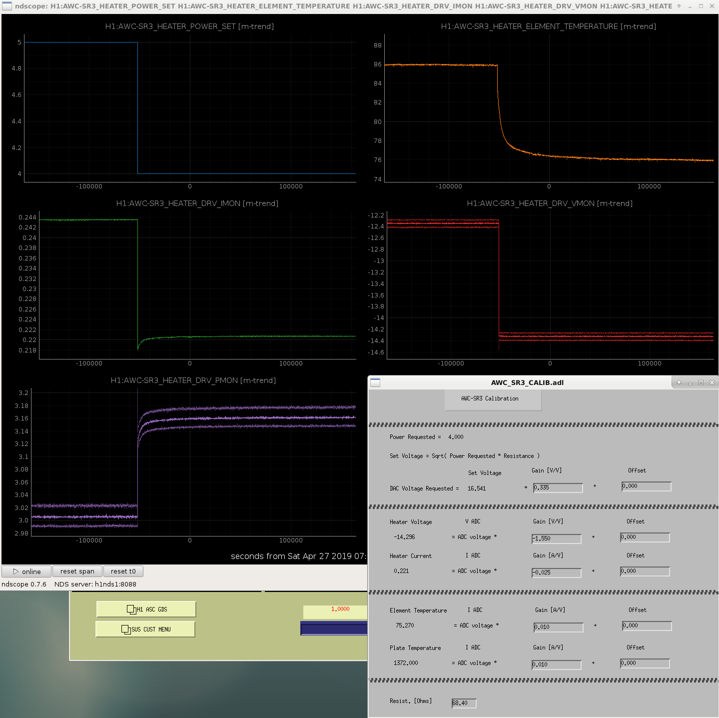
Georgia and Jeff alerted me to some strange behaviour in the SR3 heater. The power monitor channel (PMON = product of IMON and VMON) is not reporting anything like the same power as the requested power (although it is correctly reporting the product of IMON and VMON).
The attached image shows that when PSET is changed from 5W to 4W, the voltage monitor channel changes from -12.2V to -14.4V. Even accounting for a possible error in the sign, the magnitude of this change makes no sense: a 20% reduction in power should correspond to a 10% reduction in voltage but we see an 18% increase in the magnitude of the voltage monitor. The VMON calibration shows that the OFFSET is set to zero.
I've asked TJ to look into the Beckhoff code that is calculating these monitor channels to try to determine if this is a software or hardware issue.
Maintenance activites ended just before noon, and then locking commenced. (times in UTC)
1855: Started initial alignment.
1907: Inital alignment complete, starting locking.
2038: Reached DC Readout.
Swept EndX
Swept EndY
[Georgia, Jenne]
Terra called the control room and helped me excite the mode by increasing the gain in the dampining filter for mode 24 (no excitation required). We excited the mode until the PI_ESD_DRIVER_OUT monitors were several thousand counts. Though as we increased the gain we saw some broadband noise around our mechanical modes.
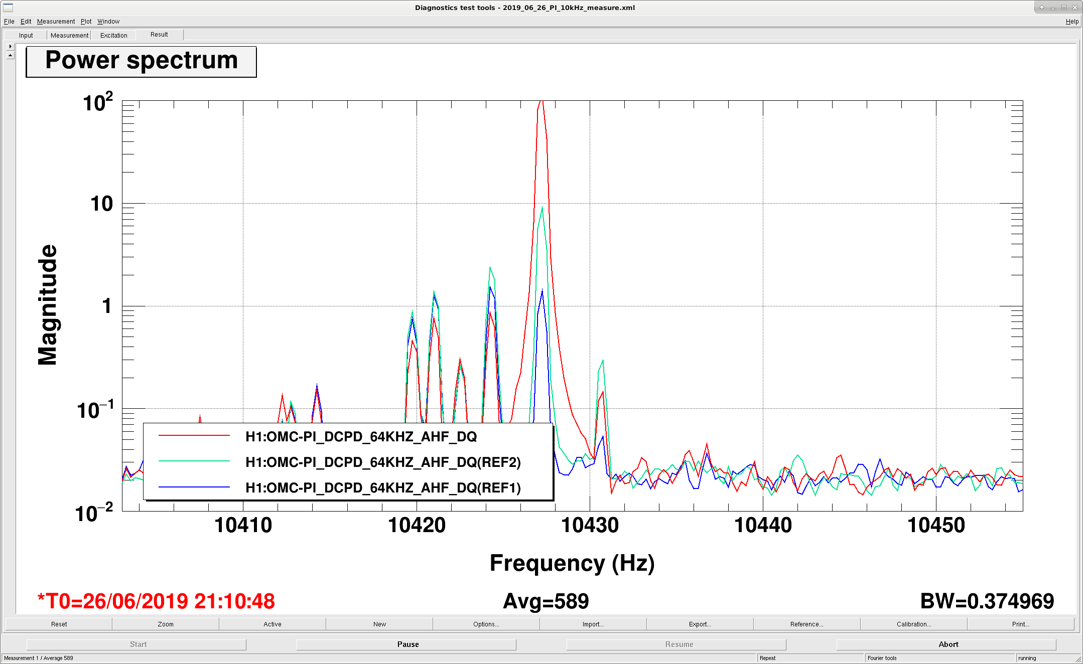
We set the ESD output matrix in the butterfly configuration (diagonal quadrants out of phase) and managed to ring up the slightly-lower-frequency 10.428 kHz mode (see first attachment, red is with the mode rung up). We then switched to the drumhead configuration (diagonal quadrants in phase), and managed to ring up the same mode again. So as yet we have not distingushed which mode this really is.
They saw something similar at LLO, and looked at the downconverted transmon QPD signal to distinguish between the two modes. During the first round of excitations I had the TR_Y QPD input matrix in the drumhead configuration (all quadrants added together). For the second round of excitations we switched the matrix to a pringle-mode. I will need to look back at the data and see if we saw our down-converted excited mode in the QPD.
Second attachment is the broadband noise with the ETMY ESD bias on, as noted by Jenne above.
The beams on the TransMon QPDs are so off-center that it might be hard or not possible to identify the modes using them. On each QPD (A & B) the lowest light segment has about 20x less light on it than the highest light segment. I think you'll need to center the beams on the QPDs to use them as a diagnostic.
I had a look anyway, and only see the downconverted mode when the Transmon QPD input matrix is in the pringle configuration, suggesting that the 10.427 kHz mode is a flower mode of ETMY. (I'm not sure if this is using only one QPD or some combination of both, it's not obvious to me from the PI screen.)
We didn't manage to ring up the 10.4305 kHz mode with our ETMY excitations, perhaps it is on a different test mass?
The last plots in this thread could be misleading. Slawek has pointed out that the QPDs should see the second order optical mode, but the linewidth we saw was too narrow for this... Maybe some electronic cross-talk?