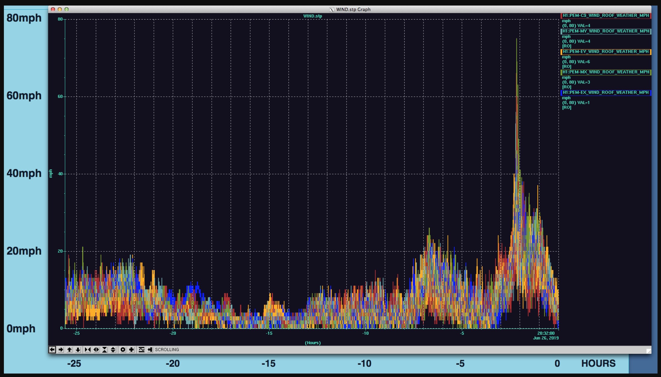
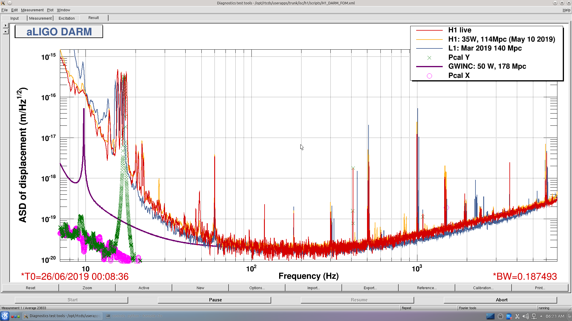
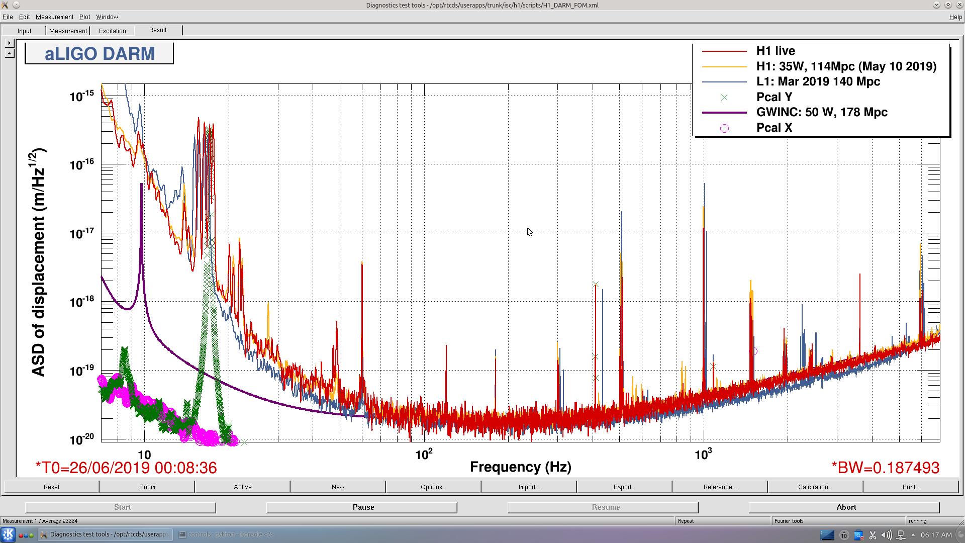
Calibration work was followed by a big storm which passed through. (see attached screenshot with a gust over 70mph!)
Then I had issues with a CLOSED shutter on ALSx (took me a while to figure that out while I steered optics around). :(
Now I'm going through an alignment to undo the steering I did.
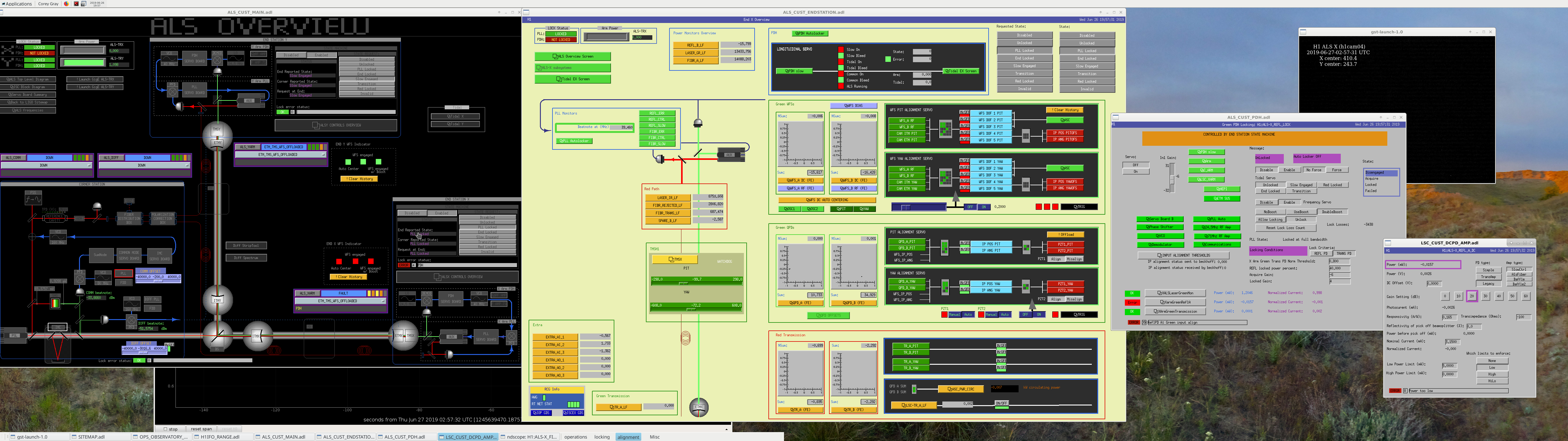
After the storm was passing through, ALS x & y were obviously flashing all over the place. Unfortunately, within a few minutes the green spot for ALSx disappeared (and we had the error: "ReflPD A; Green input align").
1) Looking at ETMx, TMSx, & ITMx
Saw shifts for all of these guys, so I returned them to where they were during the lock, but no change for the spot on video.
2) ENDx Overview: No spot for Green WFS (& offcenter spots for Green QPDs)
3) PDH Locking screen:
Attached is a screenshot of the issue. Since the power is low I'm wondering if this is still an alignment issue & I just need to sweep optics to get something on the camera. But I don't really know where to start and where to go. This is something I can try next.
For the GREEN WFS, I'd prefer to not touch picomotors to get a spot on them, but I'm wondering if ETMX/ITMx/TMSx alignment sweeps could help this?
...........Oh Darn........
As I was going through the Troubleshooting wiki, there is mention of: If one has symptoms as above (i.e. no power for XARM Green ReflA), one should check the shutters. I just saw that the ISCTEX green shutter was CLOSED. I opened it and I atleast now see light (ugly light, but light). Why would this shutter close on me???
OK, now that I'm not blind, going to try and find the spot for Green X-arm!
5 Min Later:
Ugh. That did the trick. Unlocked ALSx & tweaked ETMx & (mostly) TMSx to get flashing from 0.1 up to 1.0. Now will move on...hopefully an alignment is not needed for the touching I did to the ITMx.
PRMI Flashes look like garbage (no flashing at all with PRM tweaks after BS tweaks from CHECK MICH FRINGES). Going for an alignment.
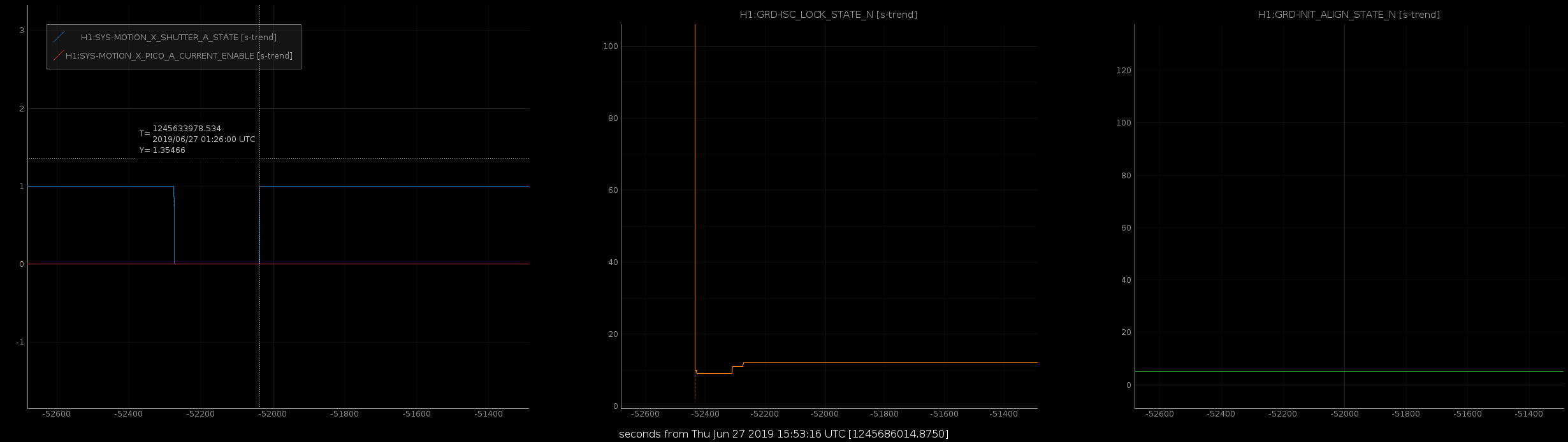
The ALSX shutter closing does not seem to be caused by the enabling of the picomotors, as seen with FRS 11354.
It was closed when the ALS_XARM node set H1:SYS-MOTION_X_SHUTTER_A_OPEN => 1 when it was starting to lock. I'm not sure why asking it to open actually closed it. Filed FRS 13154
2019-06-27_01:26:00.954991Z ALS_XARM executing state: LOCKING (-20)
2019-06-27_01:26:00.960283Z ALS_XARM [LOCKING.main] ezca: H1:SYS-MOTION_X_SHUTTER_A_OPEN => 1
2019-06-27_01:26:00.962242Z ALS_XARM [LOCKING.main] ezca: H1:ALS-C_LOCK_REQUESTX => End Locked
2019-06-27_01:26:00.963586Z ALS_XARM [LOCKING.main] ezca: H1:ALS-X_WFS_SWITCH => OFF
2019-06-27_01:26:00.964060Z ALS_XARM [LOCKING.main] ezca: H1:ALS-X_WFS_DOF_1_P_RSET => 2
2019-06-27_01:26:00.964461Z ALS_XARM [LOCKING.main] ezca: H1:ALS-X_WFS_DOF_2_P_RSET => 2
2019-06-27_01:26:00.964862Z ALS_XARM [LOCKING.main] ezca: H1:ALS-X_WFS_DOF_3_P_RSET => 2
2019-06-27_01:26:00.965275Z ALS_XARM [LOCKING.main] ezca: H1:ALS-X_WFS_DOF_1_Y_RSET => 2
2019-06-27_01:26:00.965644Z ALS_XARM [LOCKING.main] ezca: H1:ALS-X_WFS_DOF_2_Y_RSET => 2
2019-06-27_01:26:00.966066Z ALS_XARM [LOCKING.main] ezca: H1:ALS-X_WFS_DOF_3_Y_RSET => 2
(Changed tag to CDS, FRS)
We have been watching a storm (w/ lightning, loud thunder, and high winds) approach LHO from Rattlesnake and it is currently over the LVEA (or still approaching). Have seen gusts over 70mph!!! (H1 was steadily degrading in range & finally dropped lock.)
I transitioned SEI_CONF to MORE_WINDY, but may switch back to the normal WINDY since we don't appear to have sustained winds over 40mph.
NOTE: 1:25 Robert & crew taking down time to move laser vibrometer at BSC2.
J. Kissel I gathered the following regular calibration measurements today; in summary -- the full suite. I was also able, during the sensing function portion of the measurements, to grab complementary PCALX sweeps and broadband measurements as well to further facilitate studies of the apparent a-causality of the detuned SRC spring. Total measurement time was 3.1 hours. /ligo/svncommon/CalSVN/aligocalibration/trunk/Runs/O3/H1/Measurements/FullIFOSensingTFs/ 2019-06-26_H1_DARM_OLGTF_LF_SS_5to1100Hz_15min.xml # 1/(1+G) 2019-06-26_H1_PCALX2DARMTF_LF_SS_5t1100Hz_10min.xml # C_x/(1+G) 2019-06-26_H1_PCALY2DARMTF_LF_SS_5t1100Hz_10min.xml # C_y/(1+G) 2019-06-26_H1_PCALX2DARMTF_BB.xml # from 2019-06-27 00:52:26 - 00:54:09 2019-06-26_H1_PCALY2DARMTF_BB.xml # from 2019-06-27 00:49:25 - 00:51:09 2019-06-26_H1_OMCDCPDSUM_to_DARMIN1.xml # TF to roughly convert units from DARMIN1 ct to OMC DCPD current /ligo/svncommon/CalSVN/aligocalibration/trunk/Runs/O3/H1/Measurements/FullIFOActuationTFs/ 2019-06-26_H1SUSETMX_L1_iEXC2DARM_10min.xml # A_L1*C_y / (1+G) 2019-06-26_H1SUSETMX_L1_PCAL2DARM_8min.xml # C_y / (1+G) for L1 2019-06-26_H1SUSETMX_L2_iEXC2DARM_22min.xml # A_L2*C_y / (1+G) 2019-06-26_H1SUSETMX_L2_PCAL2DARM_8min.xml # C_y / (1+G) for L2 2019-06-26_H1SUSETMX_L3_iEXC2DARM_8min.xml # A_L3*C_y / (1+G) 2019-06-26_H1SUSETMX_L3_PCAL2DARM_8min.xml # C_y / (1+G) for L3 Analysis to come.
[Rick, Sundae, Niko]
On Tuesday we investigated a loss of power range for the laser in the EX pcal transmitter module. Rick adjusted the pitch and yaw of the AOM alignment, as well as varying the distance from the transducer to try and optimize the diffraction efficiency. We were able to increase our offset voltage maximum from 6.2 V to 8 V.
We then did Tx module maintenance with the new AOM alignment (EX_06/25_tx_maintenance.pdf, EX_06/25_transfer_func.jpeg).
We finished off the long maintenance day with an end station calibration (EX_06/25_calibration.pdf, EX_06/25_beam_spots.jpeg). The beam spots are still centered (even after adjusting the AOM). Will comment later with data quality analysis.
TITLE: 06/26 Eve Shift: 23:00-07:00 UTC (16:00-00:00 PST), all times posted in UTC
STATE of H1: Calibration
OUTGOING OPERATOR: Patrick
CURRENT ENVIRONMENT:
Wind: 7mph Gusts, 4mph 5min avg
Primary useism: 0.03 μm/s
Secondary useism: 0.05 μm/s
QUICK SUMMARY:
H1 locked, and it is currently out for ongoing calibration work by Jeff K.
TITLE: 06/26 Day Shift: 15:00-23:00 UTC (08:00-16:00 PST), all times posted in UTC STATE of H1: Calibration INCOMING OPERATOR: Corey SHIFT SUMMARY: Georgia and Jenne worked on commissioning. Robert worked on PEM. Jeff currently taking calibration measurements. LOG: 15:22 UTC Heard plane flying over site 16:16 UTC Sundae to optics lab 16:17 UTC Ken to communication room 16:29 UTC S&K electric, replacing emergency light fixtures (WP 8262) 17:58 UTC Karen to mid Y 18:06 UTC Observatory mode to commissioning 18:16 UTC Ken to change room to add a light 18:17 UTC Robert, Matthew, and Adrian to LVEA to start PEM work 18:19 UTC Vanessa to mid X 18:24 UTC Ken to air handler room 18:41 UTC Karen leaving mid Y 18:43 UTC Set SEI_CONF to EARTH_QUAKE 19:25 UTC Lock loss 19:30 UTC GRB E337158. Confirmed with LLO. Unlocked, ignoring. 19:34 UTC Set SEI_CONF to WINDY 20:27 UTC Dave to end Y 20:55 UTC Dave back 21:03 UTC Kyle to mid Y 21:48 UTC Observatory mode to calibration 22:58 UTC Chandra to mid Y
Jeff K, Dave:
For each IOP model:
1) if safe.snap and OBSERVE.snap were links to separate but equal files, changed OBSERVE link to point to safe.snap file
2) if safe.snap and OBSERVE.snap were links to separate and different files, made safe.snap = OBSERVE.snap and changes OBSERVE link to point to safe.snap file
only h1iopoaf1 needed no changes. 13 IOP models matched 1) and 16 IOP models matched 2) making 30 total IOPs.
Following my discovery that h1iopiscey was not setting its DACDT to On until last week, today Jeff and I turned on h1iopiscex's DACDT.
So far its looking promising following the replacement of sw-ex-h1daq Netgear by Brocade. 24+ hours and no further CRC errors. We should know more definitely by the end of the week.
BTW: we were able to see corresponding switch port errors on the Netgear using LibreNMS plots, details in the CRC wiki page This gives us confidence that replacing the switch will fix this error.
[Georgia, Jenne]
Terra called the control room and helped me excite the mode by increasing the gain in the dampining filter for mode 24 (no excitation required). We excited the mode until the PI_ESD_DRIVER_OUT monitors were several thousand counts. Though as we increased the gain we saw some broadband noise around our mechanical modes.
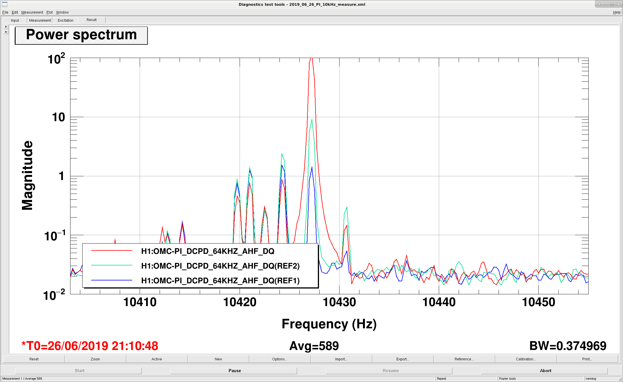
We set the ESD output matrix in the butterfly configuration (diagonal quadrants out of phase) and managed to ring up the slightly-lower-frequency 10.428 kHz mode (see first attachment, red is with the mode rung up). We then switched to the drumhead configuration (diagonal quadrants in phase), and managed to ring up the same mode again. So as yet we have not distingushed which mode this really is.
They saw something similar at LLO, and looked at the downconverted transmon QPD signal to distinguish between the two modes. During the first round of excitations I had the TR_Y QPD input matrix in the drumhead configuration (all quadrants added together). For the second round of excitations we switched the matrix to a pringle-mode. I will need to look back at the data and see if we saw our down-converted excited mode in the QPD.
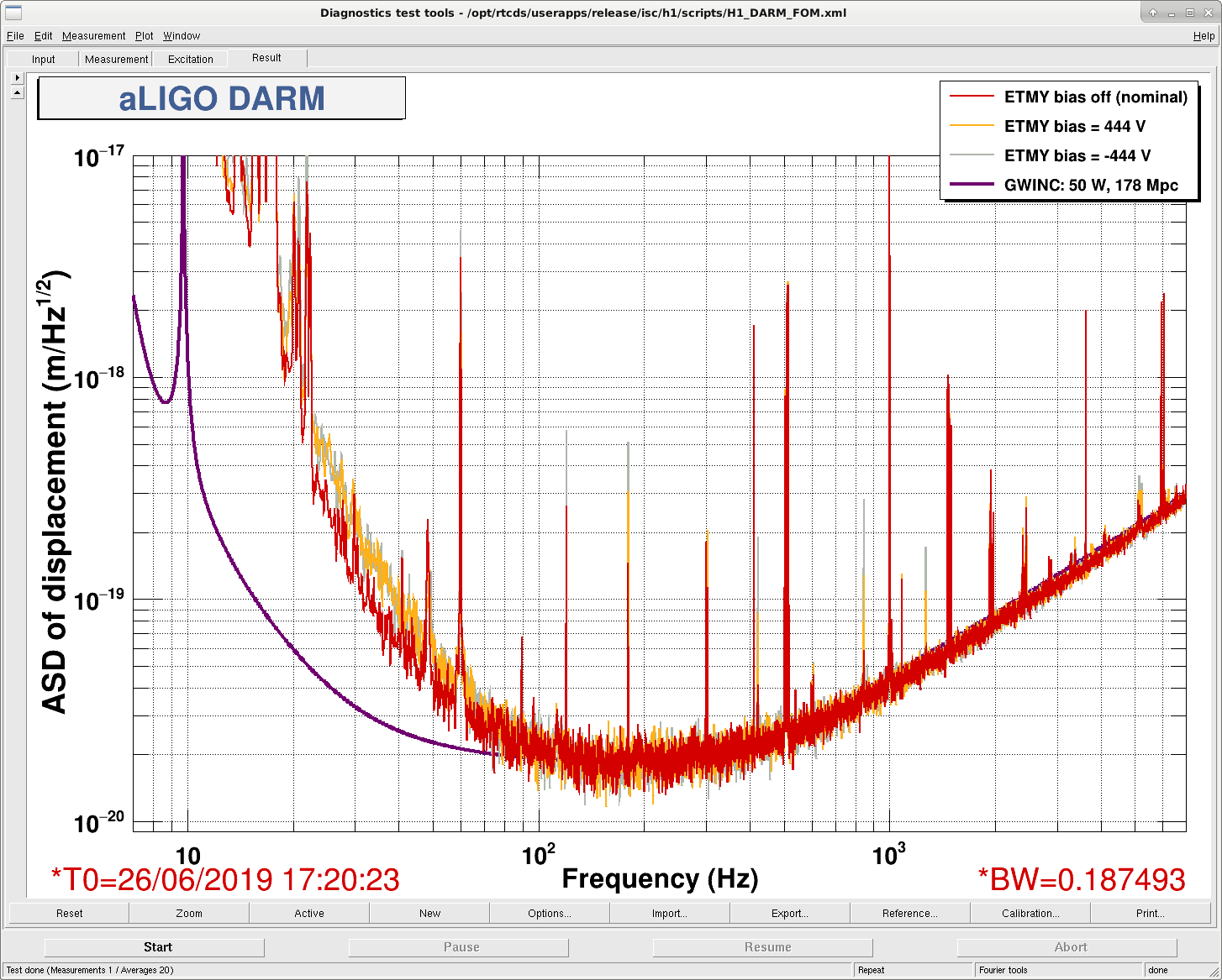
Second attachment is the broadband noise with the ETMY ESD bias on, as noted by Jenne above.
The beams on the TransMon QPDs are so off-center that it might be hard or not possible to identify the modes using them. On each QPD (A & B) the lowest light segment has about 20x less light on it than the highest light segment. I think you'll need to center the beams on the QPDs to use them as a diagnostic.
I had a look anyway, and only see the downconverted mode when the Transmon QPD input matrix is in the pringle configuration, suggesting that the 10.427 kHz mode is a flower mode of ETMY. (I'm not sure if this is using only one QPD or some combination of both, it's not obvious to me from the PI screen.)
We didn't manage to ring up the 10.4305 kHz mode with our ETMY excitations, perhaps it is on a different test mass?
The last plots in this thread could be misleading. Slawek has pointed out that the QPDs should see the second order optical mode, but the linewidth we saw was too narrow for this... Maybe some electronic cross-talk?
Per WP 8256, took SEI systems down at the Corner and independently at Endy, to check the fluid accumulators' gas charge. Not one accumulator needed charging in the corner station nor at EndY. Did not attempt EndX as Pcal work was going on.
Then EndX will not take very long, maybe 1 hour and we'll do that as soon as tolerable. I'll venture that the 7 accumlators at EndX will be fine but that venture will likely be all it takes to insure that at least one will need charging so better plan on checking.
Did EndX Accumulators today. Were it not for the gas loss when I got the gauge stuck on the valve on one unit on the Pump Station, no accumulator on the site needed charging this quarter.
Closing WP 8256
TITLE: 06/26 Day Shift: 15:00-23:00 UTC (08:00-16:00 PST), all times posted in UTC
STATE of H1: Observing at 115Mpc
OUTGOING OPERATOR: Ed
CURRENT ENVIRONMENT:
Wind: 10mph Gusts, 6mph 5min avg
Primary useism: 0.02 μm/s
Secondary useism: 0.06 μm/s
QUICK SUMMARY: No immediate issues.
TITLE: 06/26 Owl Shift: 07:00-15:00 UTC (00:00-08:00 PST), all times posted in UTC
STATE of H1: Observing at 117Mpc
INCOMING OPERATOR: Patrick
SHIFT SUMMARY:
LOG:
THe 48Hz peak is "breathing" rather prominently in DARM.
WP8247 upgrade EX DAQ network switch to Brocade (Ruckus ICX-7150-24)
Dave:
The upgrade of the switch itself went as planned. Problems arose when I activated a port on sw-ex-h1fe to connect the new switch to the ADMINLAN.
After having previously done this upgrade at EY in March of this year, the switch swap-out went smoothly. With the proper tools (e.g. right-angled screwdriver), removing the obscured rack screws went well. Removing the side of the rack (with key) and the left 'ear' on the outgoing Netgear and the incoming Brocade allowed the switches to be retracted into the rack and removed though the side.
Powering down the Netgear sw-ex-h1daq did not cause any other systems' DAQ data to go bad. Once the Brocade sw-ex-h1daq was started, all the EX front ends and the pem at MX recovered their DAQ data.
To connect the new switch to the ADMIN LAN we are currently running an ADMIN ethernet cable over from the local h1fe switch (the tagging of this VLAN from the MSR is not currently working). I converted a slow controls port to an ADMIN port (0/7) on sw-ex-h1fe for this purpose. Unfortunately this was a tagged ADMIN port (from when we used to pair front end FE-LAN and IPMI on a single port) which caused some network issues mentioned in other alogs.
I'll keep this workpermit open to cover fixing the tagging of the ADMIN LAN from the MSR to the end station switches.
Beckhoff code changes:
Daniel, Patrick, Hugh:
As reported elsewhere, corner and end station Beckhoff restarts for new code were made. The Beckhoff SDF faux-models required restarts.
Due to time constraints and other activities requiring the DAQ, these two items were postponed.
Note that this means the new slow controls channels created today are not in the DAQ.
Some more details on the switch swap:
The original single mode SFPs were moved over to the new switch. I was careful to not mix them up, so the one communicating to the corner station is in 1/3/2 and the one communicating to Mid-X is in 1/3/4. Basically the switch itself was changed, but all fibers and SFP were not.
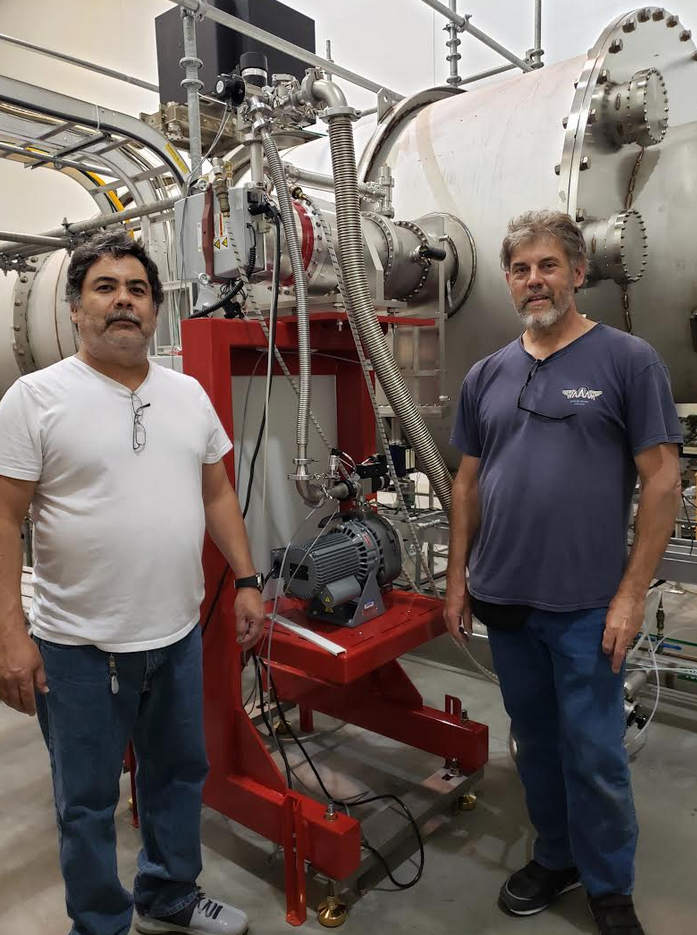
{Kyle, Gerardo, Chandra}
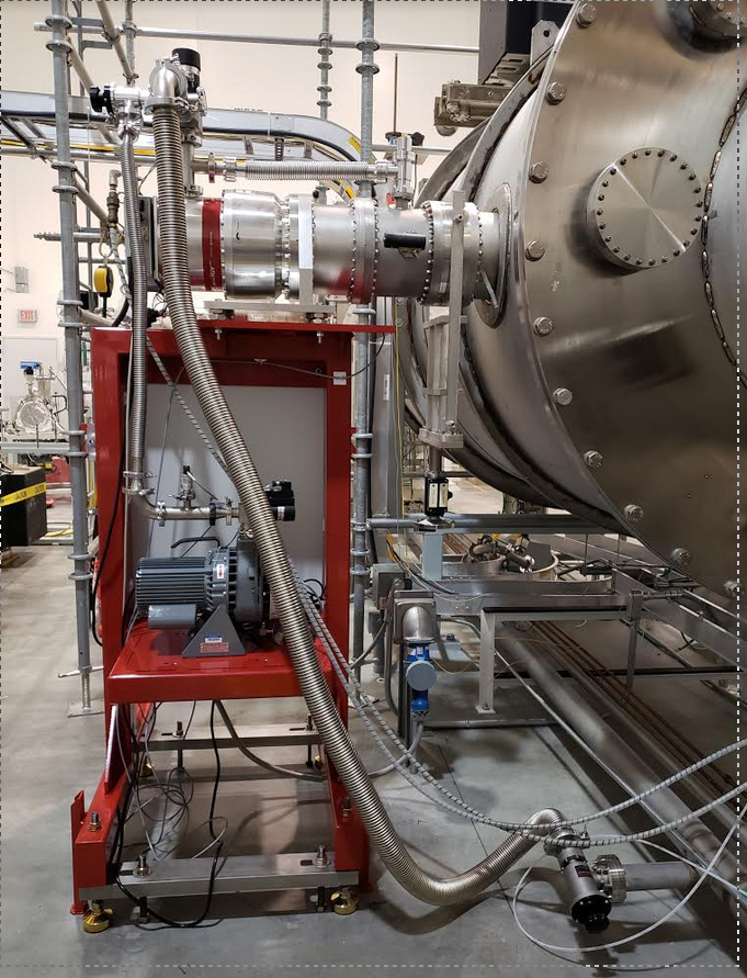
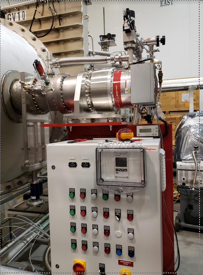
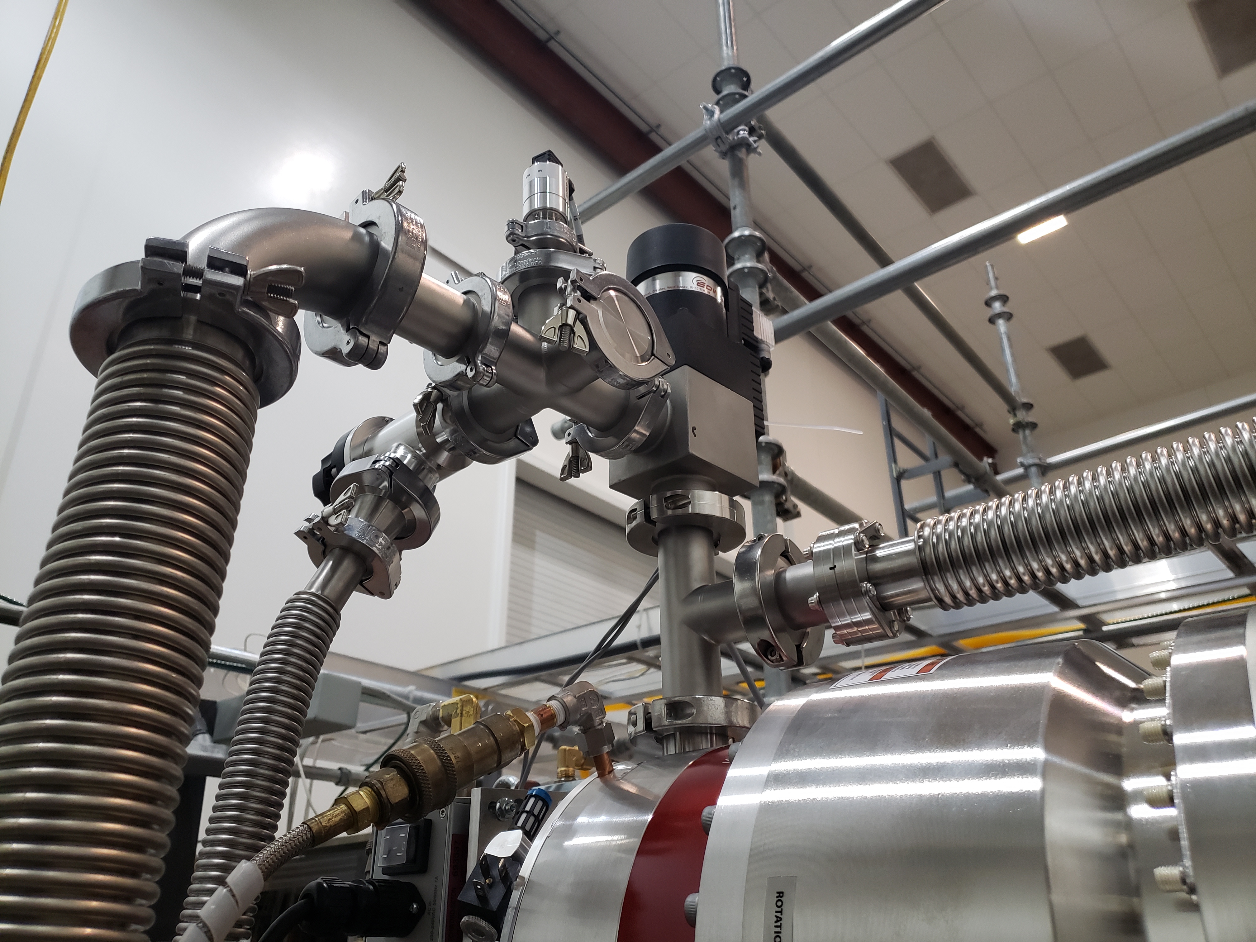
Installed the first new main turbo pump station on main volume today at mid-y station. All went smoothly. We hard closed GV10 and GV11 and performed a full visual inspection on the actuator per Q1800019 and will make notes in the google sheet.
All vacuum seals are leak tight with the leak checker bottomed out at 1e-10 Torr-L/s of He, except for the manufacturer turbo vent valve which leaked in mid -9 range. We plan to replace those components with blanks and added an after market vent valve on 6-way cross.
We spun up the turbo and tested a few controls functions. The new three-position switch mod works as intended. The pressure fell to 1e-7 Torr.
This task took most of the day and GVs were closed from about 8:30 am to 4:30 pm. Gerardo and Kyle bumped them open to slowly peel away the o-rings.
The new safety valve is a spring closed, electro-magnetic style, so no more need for instrument air. We found a small air leak in the instrument air line in mechanical room and notified Bubba.
Good work, team!
Work permit 8250 closed.
Here are some MC_F spectra.
Modal analysis of the reference cavity can be found at the 40m wiki.
Here is the same spectrum with updated calibration. I neglected the 2 poles around 15kHz (Change 3 in E1900103).
The calibration for MC_F is:
In transmission of the IMC the cavity pole at 8.8kHz needs to be added.