Closes FAMIS 28420, last checked in alog 86471.
IX did not run with the following error popping (only error lines copied):
Coherence for bias_drive_bias_off is 0.015409917227075794, which is below the threshold of 0.1. Skipping this measurement
Cannot calculate beta/beta2 because some measurements failed or have insufficient coherence!
Cannot calculate alpha/gamma because some measurements failed or have insufficient coherence!
Something went wrong with analysis, skipping ITMX_13_Hz_1440255043"
Coherence for bias_drive_bias_off is 0.0825334918693312, which is below the threshold of 0.1. Skipping this measurement
Cannot calculate beta/beta2 because some measurements failed or have insufficient coherence!
Cannot calculate alpha/gamma because some measurements failed or have insufficient coherence!
Something went wrong with analysis, skipping ITMX_13_Hz_1438440647
Previously analyzed ETMY_12_Hz_1439650262 - skipping
Analyzing data in ITMX_13_Hz_1437835843...
Reading time series for bias_drive_bias_on
Reading time series for L_drive_bias_on
Reading time series for bias_drive_bias_off
Reading time series for L_drive_bias_off
Coherence for bias_drive_bias_off is 0.07205627679480447, which is below the threshold of 0.1. Skipping this measurement
Cannot calculate beta/beta2 because some measurements failed or have insufficient coherence!
Cannot calculate alpha/gamma because some measurements failed or have insufficient coherence!
Something went wrong with analysis, skipping ITMX_13_Hz_1437835843


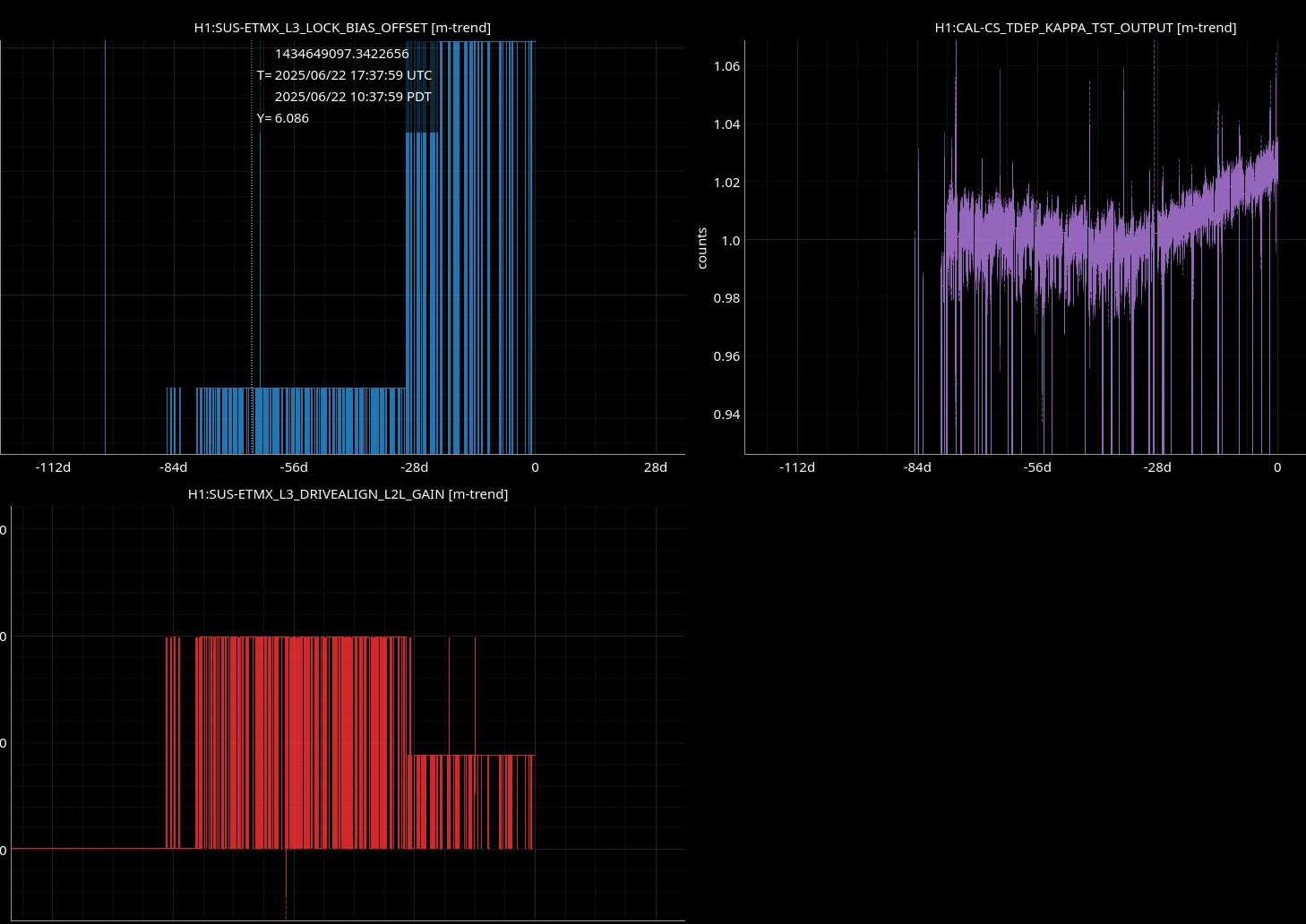
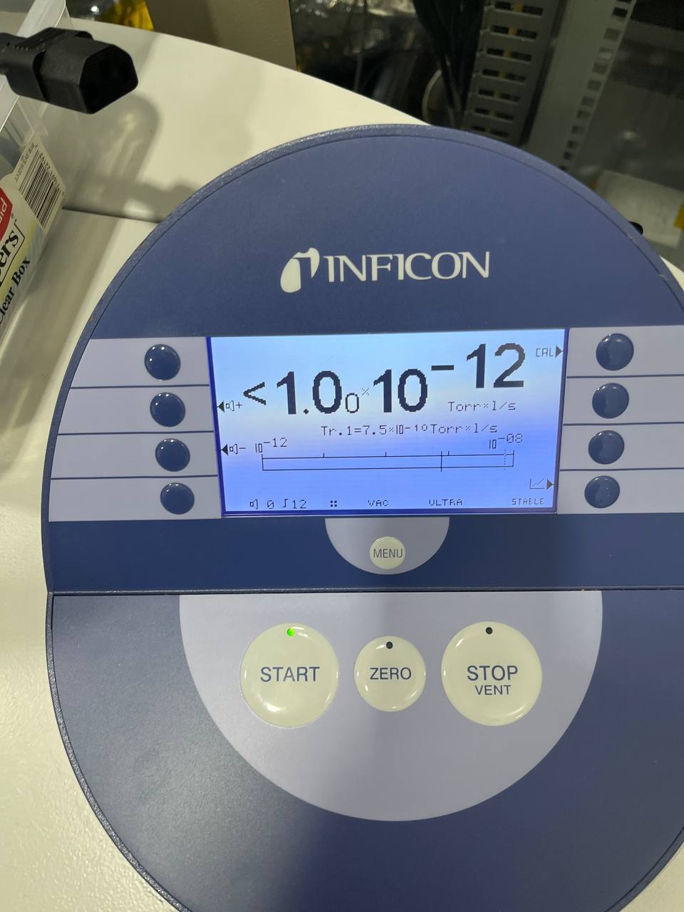
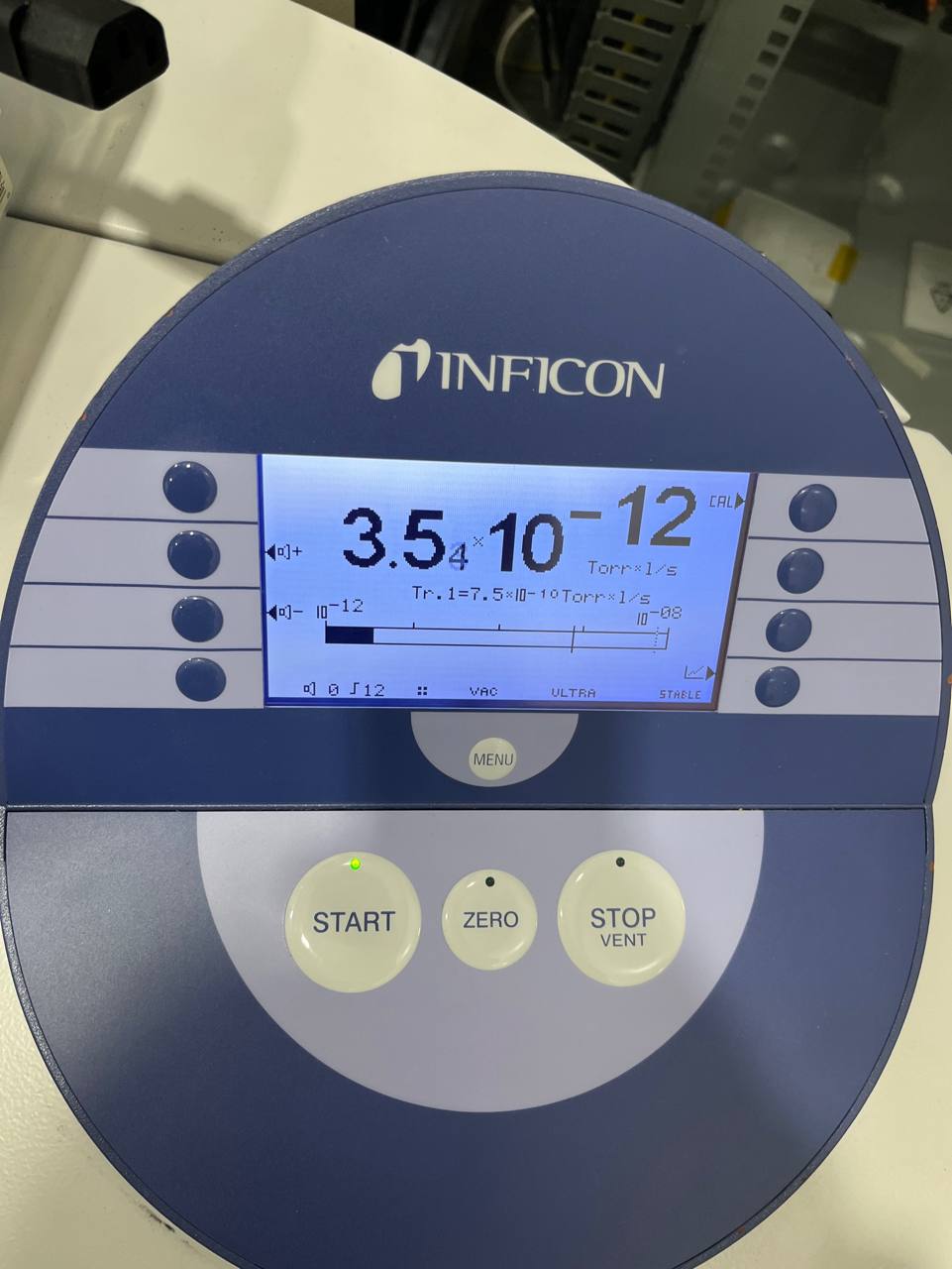
Thanks Ibrahim! In the past we've concluded that this is a good sign and means the charge build up on ITMX is low: 81858


