DQ Shifter: Sharan Banagiri
DQ Shift mentor: Pat Meyers
Summary for the week
Daily summaries:
Prevalent issues:
Some relevant alogs:
Ops Shift Transition: 05/29/2019, Day Shift 15:00 – 23:00 (08:00-16:00) - UTC (PT)
State of H1: Locked
Intent Bit: Observing
Weather: Low wind, clear sky
Primary 0.03 – 0.1Hz: 0.01 um/s
Secondary 0.1 – 0.3Hz: 0.08 um/s
Outgoing Operator: Jeff
Quick Summary: Little seismic activity or wind throughout the last shift. Locked for 18.5 hours, Observing for 16.5 hours.
Observing for the first half of the shift. Wind and microseism are low. DIAG_MAIN is reporting the seismon system is not updating. No other issues or problems.
TITLE: 05/28 Eve Shift: 23:00-07:00 UTC (16:00-00:00 PST), all times posted in UTC STATE of H1: Observing at 110Mpc INCOMING OPERATOR: Jeff SHIFT SUMMARY: Remained locked and in observing entire shift. GRB alert ~ 30 min ago. LOG: 00:08 UTC Kyle back from mid Y 00:14 UTC Mike taking film crew along arm to mid X 01:26 UTC Film crew finished on arm ~ 45 min ago, then went to overpass. Done on site, packing up. 06:30 UTC GRB alert (E334488). Confirmed with LLO. Found INJ_TRANS guardian set to INJECT_KILL, left it as is.
Have remained locked and in observing. No issues.
Philippe Nguyen, Corey Austin, Sharan Banagiri, Kara Merfeld, Anamaria Effler, Robert Schofield
O3 initial PEM injections took place mainly the weeks of March 25 at LLO and March 18 and April 15 at LHO. Hundreds of injections were made at tens of locations including acoustic, magnetic, shaking, impulse and RF injections (DTT files: https://lhocds.ligo-wa.caltech.edu/exports/pem/19aMarPEMinjections/LHO). A preliminary report was prepared, https://alog.ligo-wa.caltech.edu/aLOG/index.php?callRep=47881, we reference it below when it contains more detail then presented here.
A. Vibration coupling
1) Worst site: LLO EX transmission monitor
The large drops visible in LLO’s range as anthropogenic vibration levels increase, are associated with the EX transmission monitor. The noise has a higher SNR in the pitch and yaw signals from the quad diodes than it does in DARM. Thus, the diodes witness the noise before it is combined with other noise in DARM. Candidates include scattering and servo noise. https://alog.ligo-la.caltech.edu/aLOG/index.php?callRep=46147
2) Next worst sites: at LLO are EY and HAM5/6 and, at LHO, HAM5/6 and the PSL followed by EY
Figure 1 indicates the sites at LHO and LLO where the ambient vibration level is estimated to make the greatest roughly linear contribution to DARM for each frequency. A rough summary of the LHO plot is that, the greatest ambient vibration contribution to DARM is in the HAM5/6 area below 100 Hz, and in the PSL area above 100 Hz. The rough summary for LLO is that the worst sites are HAM5/6 and EY, and both are a significant contribution to DARM below 100 Hz.
The plots are made by first calculating a coupling function (meters of DARM per meter of motion at sensor) for each sensor for each of multiple injections, and then producing a single coupling function for each sensor, using an algorithm to select the best of the multiple injections, usually the loudest relative to other sensors. The coupling function is multiplied by the ambient vibration level to produce an estimate of the ambient contribution to DARM. At each frequency in the plot, the sensor or sensor region with the highest estimated contribution to DARM is indicated by color, and the estimated contribution plotted.
These estimates are for banded linear coupling. When we notice upconversion, we study it separately, injecting in narrow bands to find the motion frequencies responsible for the upconversion. The estimates in Figure 1, however, may be somewhat distorted by upconversion: if the upconverted noise is within the injection band, that noise is assumed to be produced by the injection at the frequency that the upconverted noise appears at in DARM. This tends to be more of a problem for scattering, since it is so non-linear, than for beam jitter. We did not find cases of upconversion, other than at the ETMX transmission monitor, that would alter these estimates of the worst coupling.
These plots, other summary plots, and coupling functions for every relevant PEM sensor are located at PEM.LIGO.ORG, press the “coupling functions” button.
3) At both sites, HAM5/6 coupling is likely at the septum
The coupling at HAM5/6 was narrowed down to the septum at both LHO and LLO, using impulse injections. https://alog.ligo-wa.caltech.edu/aLOG/index.php?callRep=48886
4) EY coupling at LLO is likely in the manifold, at LHO, it may in the ETMY chamber. More evidence is needed to be confident that baffling the rest of the periscope and the Pcal beam nozzles will fix the LLO EY coupling problem.
Impulse injections suggest that the vibration coupling site at LLO EY is in the manifold (near the Pcal periscope) and, with less certainty, that the coupling site at LHO EY is in BSC 10. Resonance structure of the signals suggest that we don’t have accelerometers on the coupling sites. There are some glints visible from the un-baffled part of the LLO EY periscope, but other sites have similar glints. There is the possibility of scattering from the Pcal beam nozzle, but shaking was inconclusive. More evidence is needed in order to be confident that baffling the rest of the periscope and the Pcal beam nozzles will fix the EY coupling problem. https://alog.ligo-la.caltech.edu/aLOG/index.php?callRep=46208
5) HAM5/6 coupling at the septum window?
The coupling at the septum may be at the window: a bright scattered light spot is visible on the septum window at LHO, at a viewpoint 3 degrees from the beam. https://alog.ligo-wa.caltech.edu/aLOG/index.php?callRep=48965
However, no spot was observed at LLO at 28 degrees (the 3 degree view was not available), https://alog.ligo-la.caltech.edu/aLOG/index.php?callRep=45980 , and updated scattering estimates from Peter F. suggest that the window could not account for the scattering unless there is some imperfection https://alog.ligo-la.caltech.edu/aLOG/index.php?callRep=46272 .
One mitigation possibility would be to remove or angle the window and hedge our bets by also baffling the light-accessible regions of the septum.
Other beam spots on LLO HAM6: https://alog.ligo-la.caltech.edu/aLOG/index.php?callRep=45378, https://alog.ligo-la.caltech.edu/aLOG/index.php?callRep=44985
OMC REFL beam not the cause of the main HAM5/6 scattering: https://alog.ligo-la.caltech.edu/aLOG/index.php?callRep=46010 .
6) IO jitter coupling at both sites
Figure 2 shows jitter coupling for both sites.
7) Comparison of LLO EY and EX in-lock photos
Relevant to the source of coupling at both the TMSX and EY, are photos taken at the LLO end stations: https://alog.ligo-la.caltech.edu/aLOG/index.php?callRep=45469
The photos show a beam spot on the mirror that sends the red beam to the ALS table, M13.
8) Shaker injections at EY produce noise similar to some anthropogenic noise https://alog.ligo-la.caltech.edu/aLOG/index.php?callRep=46089
9) Other vibration coupling
Beamtube shaking https://alog.ligo-la.caltech.edu/aLOG/index.php?callRep=45710
Coupling at LHO BS chamber, LLO BSC1, and at the reduction flanges by the ITM optical levers at both sites is shown in Figure 3.
48 Hz peak at LHO The 48Hz peak at LHO appears to be driven acoustically (though modulated by alignment or other source). See the consistently lower amplitude when the HVAC is off https://alog.ligo-wa.caltech.edu/aLOG/index.php?callRep=48919 . Acoustic and impulse injections suggest that the source is in the vertex area, possibly in BSC2, but more work is needed.
Reduction of 58 Hz chiller peak at LHO: https://alog.ligo-wa.caltech.edu/aLOG/index.php?callRep=47881
10) Vibration coupling not seen (at least 10 below DARM)
|
Site |
Location |
Injection Type |
Relevant to |
|
LHO, LLO |
mids |
Acoustic/shaker 10-100 Hz |
Beamtube scatter |
|
LHO, LLO |
IOT2L (IMC table) |
Acoustic/shaker 10-100 Hz |
Local coupling |
|
LHO, LLO |
IMC tube (HAM2-3) |
Shaker 5-100 Hz |
Local coupling |
|
LHO |
HEPI EX, EY, BS, IX, IY |
HEPI Inj 1-100 Hz, beam dof |
ACB, BS baffles, scatter |
|
LLO |
ISI all BSC and HAM |
ISI Inj 1-5 Hz, beam and r dofs |
Daytime scatter |
|
LLO |
Arm beamtube |
Shaker ~58 Hz |
Beamtube scatter |
|
LHO, LLO |
SRC tube (HAM4-5) |
Shaker 5-100 Hz |
Local coupling |
11) Vibration coupling estimates from PEM injections correctly predict environmental coupling
We usually expect the coupling functions to be good to within a factor of about 2. For the known vibration features in DARM, the 48 Hz and 90 Hz peaks, as well as several of the jitter peaks at LHO, the estimate in Figure 1 is good to within a factor of 2. In addition to this comparison to stationary features, the coupling predictions have been tested against several transients, mentioned below.
LLO DARM glitch near S190510g is correctly predicted from PEM injection coupling functions. It was produced by thunder-driven vibration at EY https://alog.ligo-la.caltech.edu/aLOG/index.php?callRep=46025
Range reduction from LHO HVAC is roughly predicted from estimates for HAM5/6. https://alog.ligo-wa.caltech.edu/aLOG/index.php?callRep=48912
Range reduction from rain at LHO is roughly consistent with PEM coupling functions https://alog.ligo-wa.caltech.edu/aLOG/index.php?callRep=49495
Range reduction from wind at LHO is roughly consistent with PEM coupling functions.
B. Magnetic Coupling
Figure 4 shows that magnetic coupling is at least a factor of 10 below DARM at both sites. The coupling function for the stochastic group estimates of inter-site correlation from the LEMIs is here:
We only have one large coil working so these estimates of magnetic coupling are made using comb injections instead of broad- band injections (because of limitations in the field amplitude we can produce with the current system). Resonances observed in magnetic field coupling from the large-coil, broad-band injections (https://alog.ligo-wa.caltech.edu/aLOG/index.php?callRep=47881 ), justify the ongoing installation of large coils so that we don’t miss similar resonances between combs. We are now dominated by electronic and cable coupling, so the coupling functions are more complex than when the coupling was dominated by permanent magnets on optics.
Weekly injections. Because cable and electronics coupling can vary with electronics work, magnetic coupling is expected to vary during the run. In O2 the coupling varied at LHO by a factor of several between the beginning and end of the run. To better understand and identify changes in coupling, we have set up weekly automatic injections for each Tuesday before maintenance. The results are here: https://lhocds.ligo-wa.caltech.edu/exports/pem/WeeklyMagneticInjection/output/
Weekly injections have also begun at LLO: https://alog.ligo-la.caltech.edu/aLOG/index.php?callRep=45731
C. RF Coupling
Figure 5 shows that we can detect 9 and 45 MHz injections at both sites with at least two orders of magnitude greater SNR on our radio receivers than with DARM.
D. Site activities
Figure 6 shows several activities in the control room that show in DARM, an animated crowd walking, rolling a chair with a person in it across the control room, and dropping a large super ball from 4 ft. I suggest that we be a little more careful with site activities in this high-detection rate era. There is a chance that new or rare noise sources, that are not well accounted for in background estimates, may result in wasted telescope time before we get a chance to retract alerts based on PEM.
Update to B. Magnetic Coupling
The results from weekly magnetic injections have now been moved to
https://ldas-jobs.ligo-wa.caltech.edu/~philippe.nguyen/weekly-magnetic-injections/output/summary/ for LHO
https://ldas-jobs.ligo-la.caltech.edu/~philippe.nguyen/weekly-magnetic-injections/output/summary/ for LLO
When we got to NLN today Jenne noticed that the beamsplitter M1 LOCK_L gain was zero (nominally 0.1), she turned off the integrator and slowly ramped the gain back on, and all was well. I looked into why this was turned off.
In the PREP_FOR_MICH state of initial alignment the BS_M1_LOCK_L_GAIN is set to zero. The gain only gets turned back on when the ISC_DRMI guardian runs through its down state from the top. In initial alignment ISC_DRMI is already in its down state, so this gain wasn't getting reset until after we lose lock and reacquire again.
To fix this we added a line to the INITIAL_ALIGNMENT state of ISC_LOCK, which will request that ISC_DRMI be in IDLE instead of DOWN. That way, straight after initial alignment, the beamsplitter will be back to nominal configuration.
This change caused several locklosses from DRMI_TO_POP today. The new edge case from DOWN to IDLE, allowed a shorter path from DRMI_3F_LOCKED to IDLE (through DOWN, not a thing we wanted to do). I've removed this edge, and instead moved the beam splitter top mass gain setting to the PREP_DRMI state.
And the reason that the guardian thought that it would be shorter to go through DOWN to IDLE is that we weren't actually sitting in the state right before IDLE, DRMI_3F_W_ASC_READY. This is because the counter in ISC_LOCK's OFFLOAD_DRMI_ASC wasn't quite right. There were two "if self.counter == 5" statements, and so only one of them was being run, and it happens that the one that *wasn't* being run is the one that requested ISC_DRMI guardian to go to that DRMI_3F_W_ASC_READY state. So, I have fixed the counter statements in ISC_LOCK's OFFLOAD_DRMI_ASC state, so now we should normally have the ISC_DRMI guardian sitting in what was supposed to be the final state. So, I think that if we needed to, we could reimplement Georgia's edges. But, the new version of just putting things in the PREP state is also fine, so for now we will leave ISC_DRMI guardian as-is.
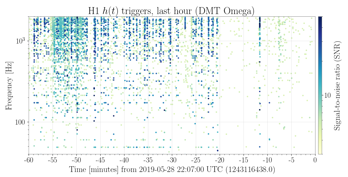
~23:43 UTC Control room noticed a series of small peaks in DARM between 20 and 60 Hz. Subsided in around less than a minute.
TITLE: 05/28 Eve Shift: 23:00-07:00 UTC (16:00-00:00 PST), all times posted in UTC
STATE of H1: Observing at 111Mpc
OUTGOING OPERATOR: Niko
CURRENT ENVIRONMENT:
Wind: 11mph Gusts, 8mph 5min avg
Primary useism: 0.02 μm/s
Secondary useism: 0.06 μm/s
QUICK SUMMARY:
No immediate issues.
TITLE: 05/28 Day Shift 15:00 – 23:00 (08:00-16:00), all times posted in UTC
STATE of H1: Observing
INCOMING OPERATOR: Patrick
SHIFT SUMMARY: Significant maintenance day activities performed today include retuning the FSS AOM, SQZ work by Sheila, and balun replacements at the end stations. Maintenance ended at noon, followed by initial alignment and then locking. Glitches in DARM were investigated and then solved after about 1.25 hours. In Observing now for 40 minutes.
LOG:
15:00 (08:00) Start of shift
15:06 (08:06) Mike, Physics Girl film crew to roof
15:08 (08:08) Karen to LVEA
15:09 (08:09) Jeff to LVEA -- reset dust monitor #6
15:16 (08:16) Mike, Physics Girl film crew to LVEA
15:19 (08:19) Jeff back from LVEA
15:38 (08:38) Bubba to LVEA -- forklift equipment
15:44 (08:44) Sheila to LVEA -- SQZ work
15:45 (08:45) Jim to EY, EX -- center BRS
15:45 (08:45) Fil, Richard to EX -- illuminator work
15:45 (08:45) Vanessa to LVEA
15:51 (08:51) Betsy to LVEA -- assisting Bubba
15:55 (08:55) Marc to EX -- balun swap
15:56 (08:56) Rick, Jason to PSL enclosure -- FSS tune-up
16:07 (09:07) Dick to LVEA -- RF measurements
16:07 (09:07) UniFirst through main gate
16:13 (09:13) TJ to LVEA -- Investigate TCSY chiller leak
16:23 (09:23) Fil, Richard back from EX
16:26 (09:26) Sheila out of LVEA
16:30 (09:30) Sheila to LVEA -- caution tape overpass
16:36 (09:36) Amber, Physics Girl film crew to LVEA
16:39 (09:39) Sheila out of LVEA
16:40 (09:40) Bubba, Betsy out of LVEA
16:51 (09:51) Karen done with MY
17:05 (10:05) Jim back from EX,EY
17:16 (10:16) Sheila to LVEA -- SQZ work
17:18 (10:18) Vanessa to EX
17:19 (10:19) EY SUS charge measurements starting
17:20 (10:20) Pep, Sharan to EBAY, LVEA -- place magnetometer, walkthrough
17:25 (10:25) TJ back from LVEA
17:37 (10:37) Marc to LVEA -- RF measurements
17:42 (10:42) Pep back from EBAY
17:48 (10:48) TJ to LVEA -- power cycle chiller
18:08 (11:08) TJ out of LVEA
18:11 (11:11) Christina to EX, EY -- collect Norco receipts
18:22 (11:22) Sheila back from LVEA
18:23 (11:23) Kyle to LVEA -- return part
18:27 (11:27) Richard to roof -- check weather system
18:28 (11:28) Kyle out of LVEA
18:41 (11:41) Dick, Marc out of LVEA
18:43 (11:43) Chris done with tractor at End Stations
18:53 (11:53) Rick, Jason out of PSL enclosure
19:06 (12:06) Film crew out of LVEA
19:06 (12:06) Starting initial alignment
19:08 (12:08) Pepsi through main gate
19:15 (12:15) Sheila to LVEA -- SQZ work
19:31 (12:31) Sheila taking SQZ area to laser hazard for alignment
19:42 (12:42) Dick to CER -- check instruments are turned off
19:46 (12:46) Jim to EY -- turn off wifi
20:02 (13:02) Sheila out of LVEA
20:05 (13:05) Finished with initial alignment, re-locking
20:06 (13:06) Jim back from EY
20:42 (13:42) At NLN, investigating frequent glitches seen in DARM
21:49 (14:49) Jim to EY -- look for sunglasses
22:18 (15:18) Going into Observation mode
22:58 (15:58) Kyle to MY -- take picture
23:00 (16:00) End of shift
FRS 9765
New Davis Weather Station was installed next to our current weather station. Unit is currently communicating with console in MSR.
F. Clara, R. McCarthy
J. Kissel, J. Oberling, J. Driggers, G. Mansell, N. Lecoeuche, S. Dwyer Once we hit Nominal Low Noise (relatively painless process, no troubles like we've been having for the past ~week), we found that DELTA L EXTERNAL was severely glitch-y, obvious both on wall ASD and in the DMT OMEGA glich-spectrogram on the wall. In the DELTAL spectrum, glitching was occuring at high frequency, so we zeroed in on the major activity of the the day that may involve that part of the spectrum -- FSS work, Balun Replacement, and Squeezer changes. - We ruled out the squeezer quickly by closing the SQZ beam diverter. - We played around with the FSS common gain, and found that gliching got much worse with the common gain (H1:PSL-FSS_COMMON_GAIN) at 16 dB, vs. what the PSL crew had set it at; 19 dB. - Sheila realized the glitching looked like what happens when the IMC VCO is in a bad place for RF whistles. - We yanked around the IMC VCO frequency (unintentionally) to some quite different place, and found that all glitching disappeared. The above process took us about 1.5 hours to figure out. We're not *really* sure what has happened, but the message is now that -- in order to have no RF whistles -- the IMC VCO requires a quite different absolute frequency (78.5 vs. 78.8 MHz). The suspicion is that -- after the FSS touch-ups today, the RefCav is now locked on a 00 mode at a different FSR. We are now running the sweep through the IMC VCO's frequency (while in observe) to find the best region, and will report more this later.
Adding spectrograms of the OMC_PI channel before (top) and after (bottom) the IMC_VCO frequency was changed. This shows the whistles very clearly.
We went to Observing for a few minutes while the IMC VCO frequency was slowly sweeping. This is something that we've done in the past to try to find better whistle-free zones (ex. alog 47987).
After talking to Keita, since this sweep would definitely take us through some whistle regions, while trying to find a nice wide whistle-free space, I have stopped the sweep and am leaving the VCO TuneOffset at the -4.95 V place that we see is pretty quiet.
Since the IMC frequency hadn't changed, and the TuneOfs hadn't changed from the previous nominal of -2.10 V, something else must have changed to make our previously nominal IMC frequency be very whistle-y. So, we should figure out what else might have changed, or we should do a full IMC VCO sweep to see if we can find a quiet region that is nice and wide, but also a little farther from the edge of the VCO's range (we're quite far from the actual edge, but the VCO becomes less-than-linear as you approach the edge).
So, for the first few minutes of this Observe segment the IMC frequency was changing slowly a small amount.
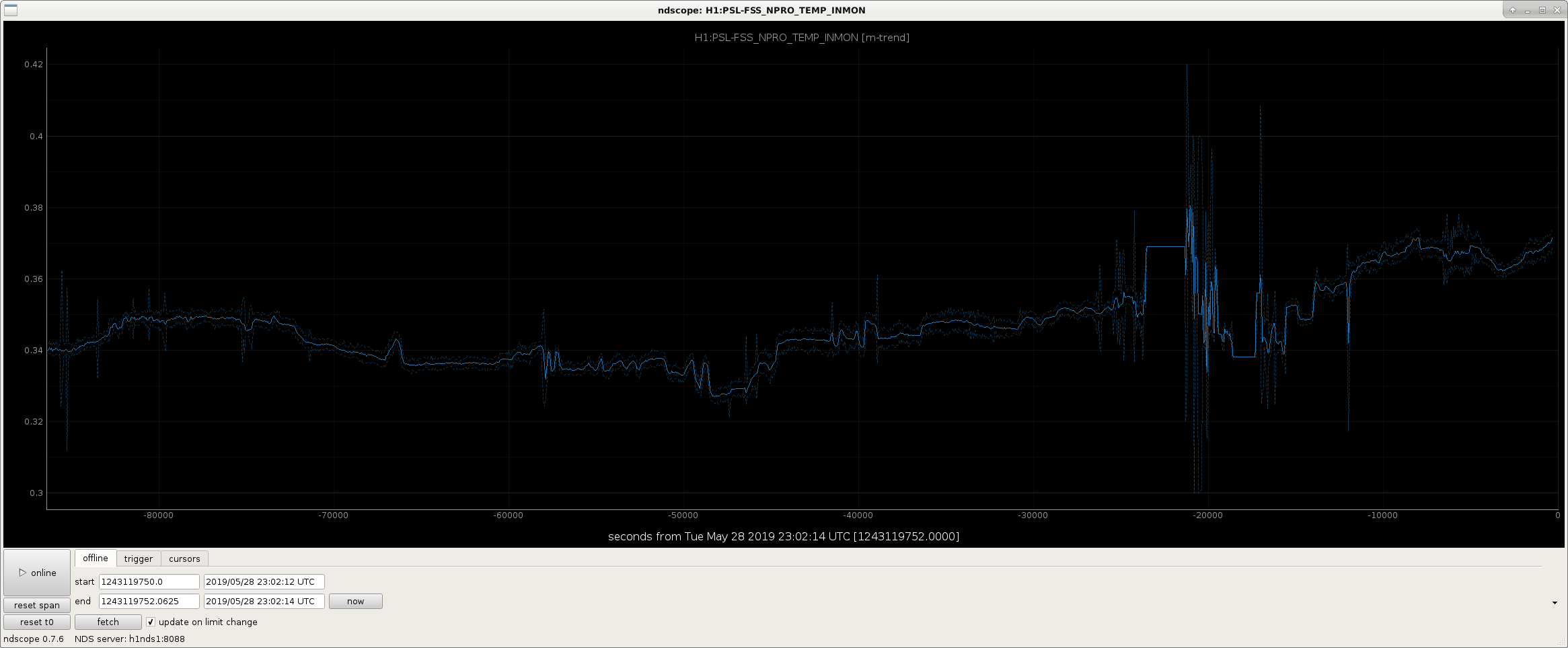
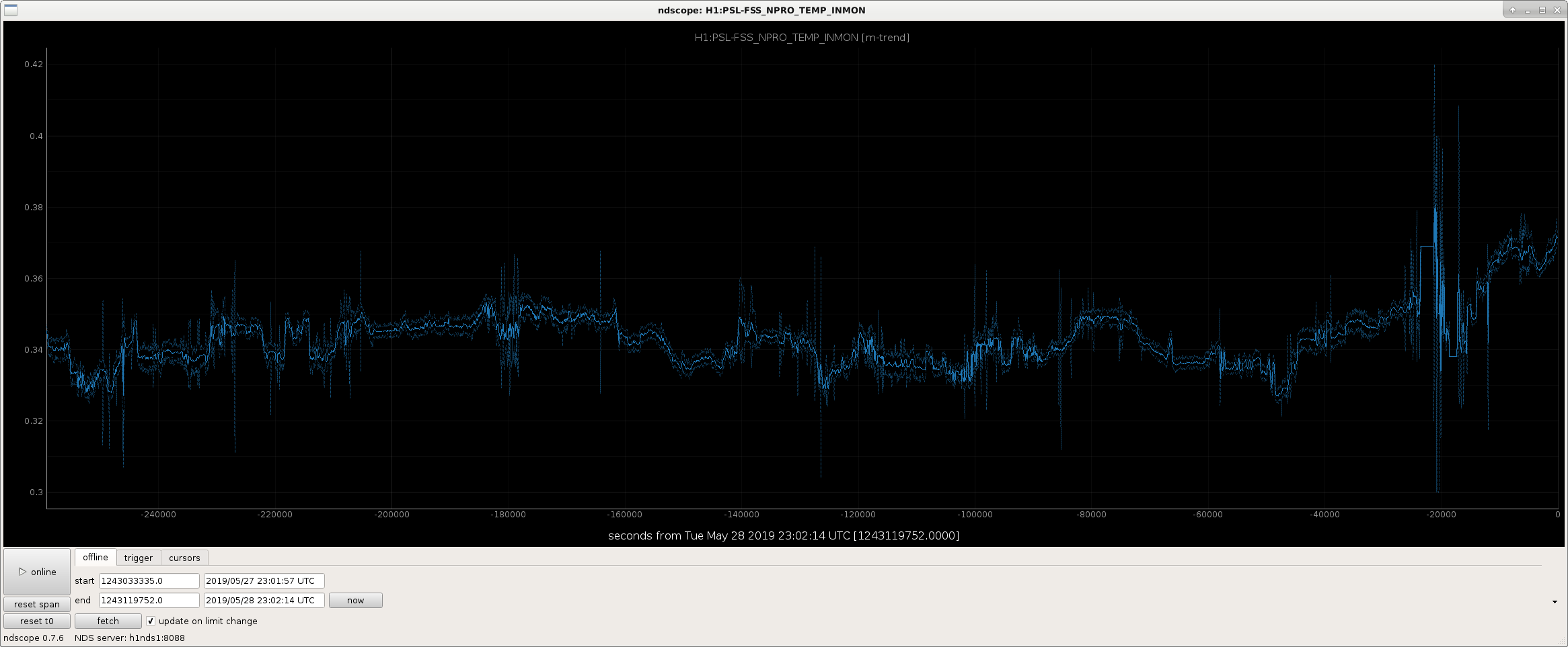
Looking at things that might have changed today, I've attached a 1-day and a 3-day trend of the PSL NPRO crystal temperature; for those not familiar, this temperature is the slow control for the FSS and is what we change if we need to lock the RefCav on a different FSR. As can be seen, we're still locking the FSS RefCav in the same region as before this morning's FSS tune-up, but it does appear to be making a move higher over the last ~4 hours (the "flat-line followed by fast changes followed by another flat-line" on the rights side of each plot are our adjustments from this morning).
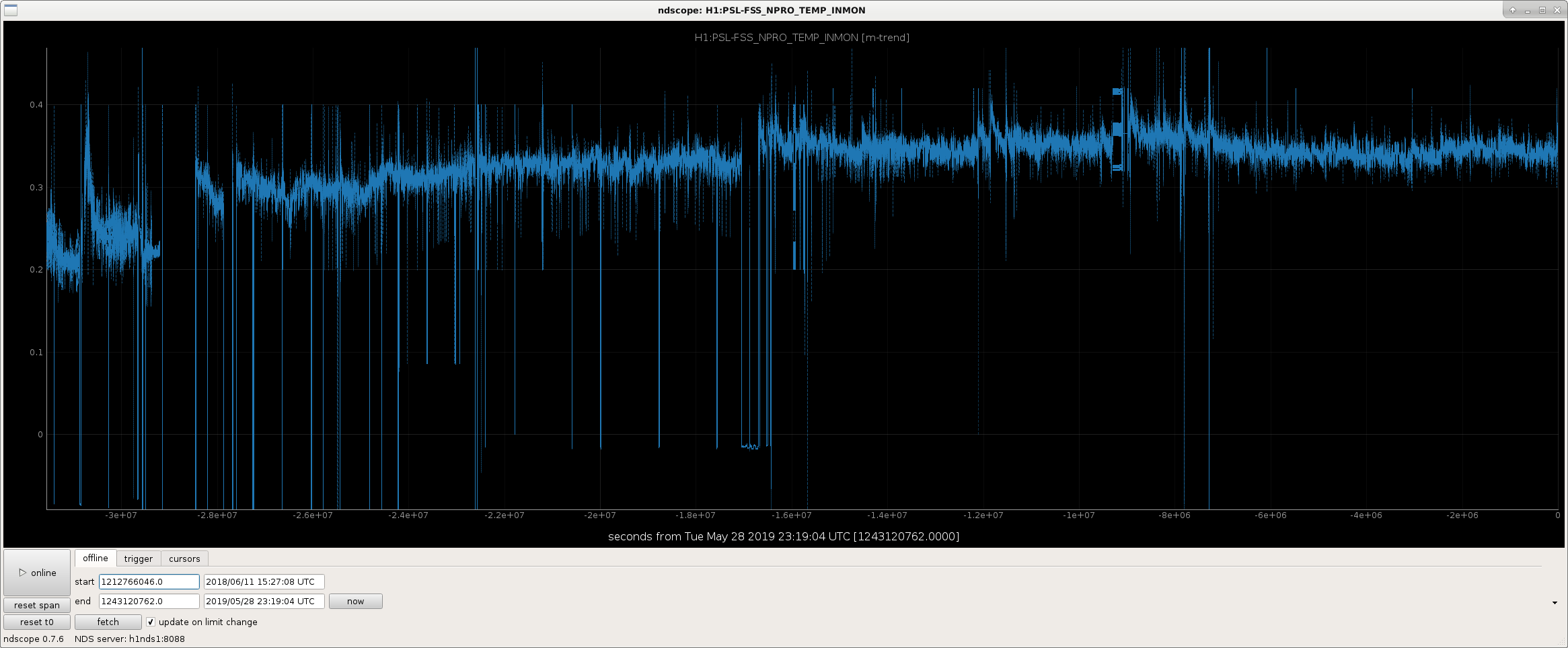
Taking the trend out to June 2018 (3rd attachment, the farthest back I can get ndscope to go at the moment), it is seen that we used to lock the RefCav with an NPRO temp of around 0.22 (we had moved up by one FSR to lock in the mid-0.3 area to make ALS happier after the 70W amp installation). It is also apparent that the FSS has run with a NPRO temp in the upper 0.3 area in the past, so the slightly higher move after we locked the RefCav this morning isn't entirely unusual.
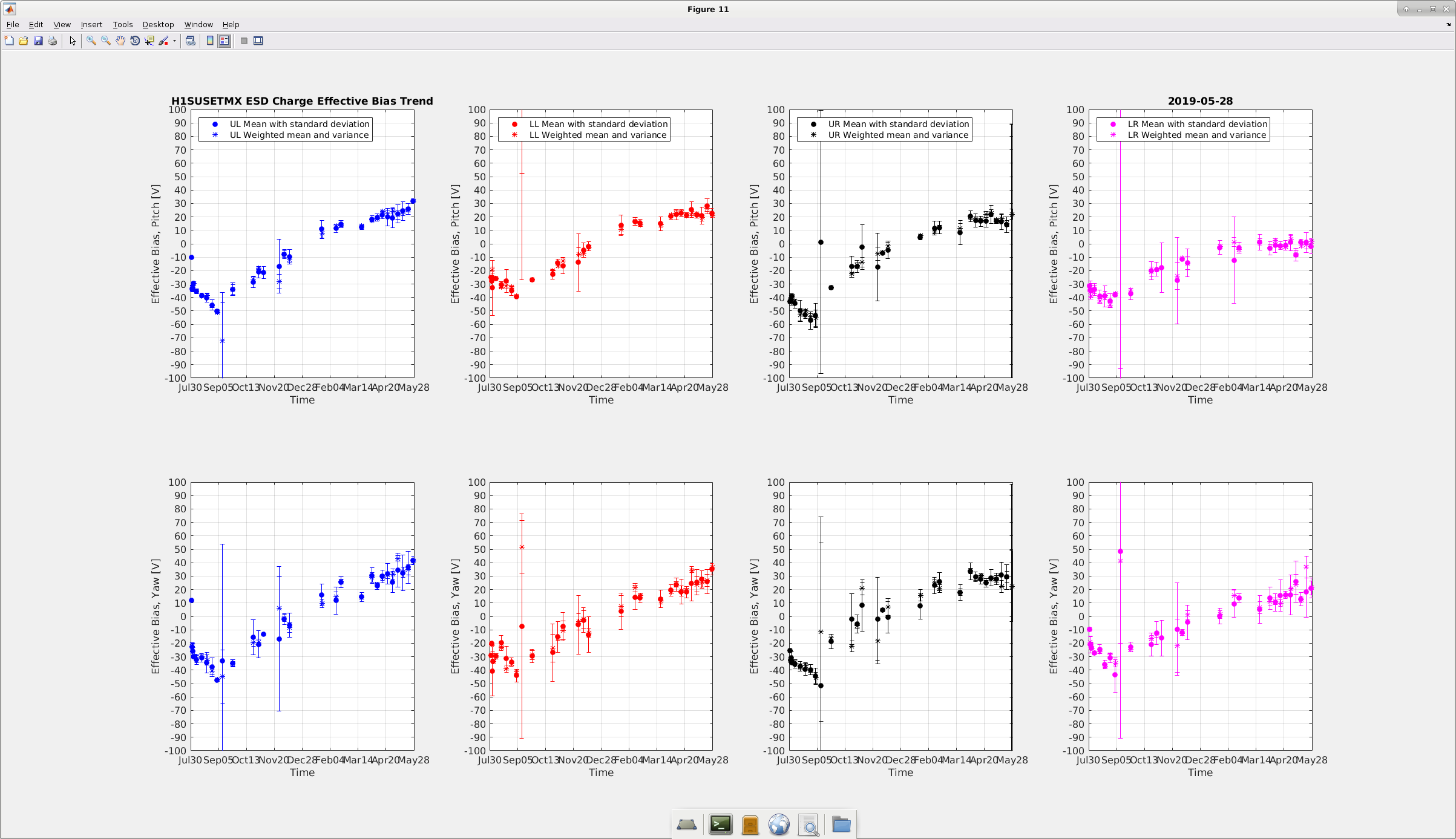
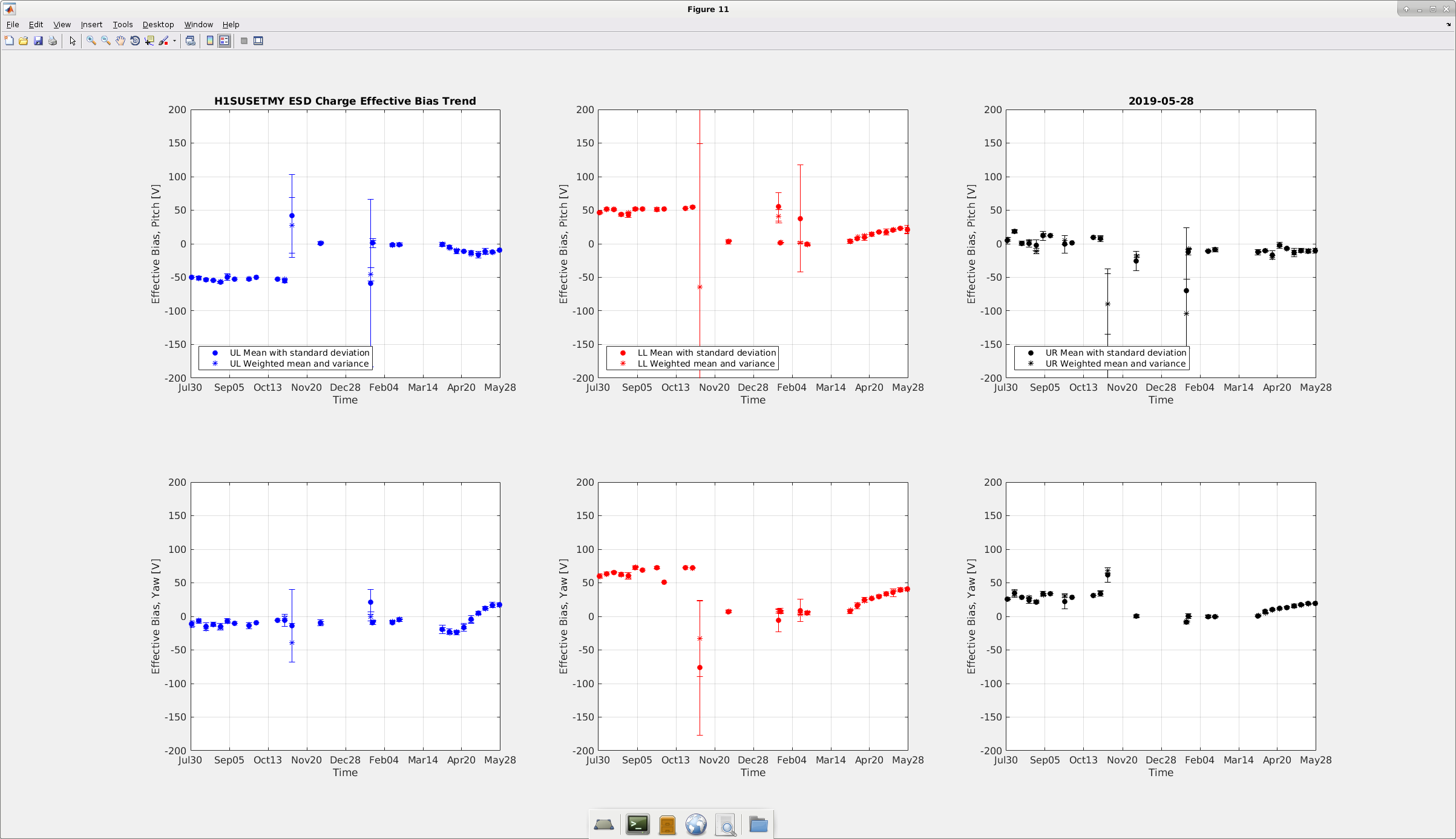
The OPLEV charge measurements were truncated today after the EX and EY tripped. We managed to take only 3 measurements for both EX/EY, attached below are the results.
ETMX: The effective bias is within the permissible limits, however for the 3rd quadrant (for both pitch and yaw) the standard deviation looks to be huge.
ETMY: once again the long term trend of the effective bias looks ok, i.e. within 30V.
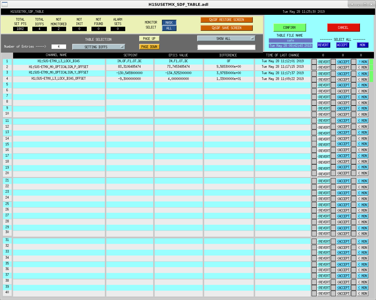
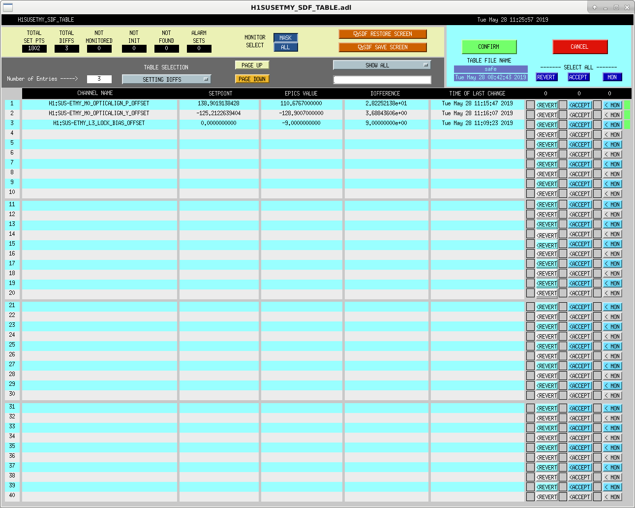
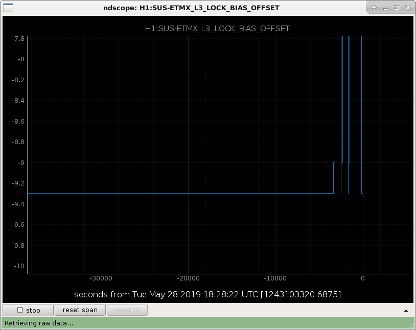
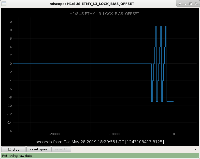
Since charge measurements were aborted midway, this lead to a few SDF difference (screenshot attached). The Lock_bias_offset for the ETMX was showing to be +4.00 instead of -9.30. I used ndscope to look for the default values during IFO Lock (pic attached). This turned out to be -9.30 V. Similarly, for the ETMY, it wa showing up as -9.0V and the default value is zero.
I made the necessary changes to remove the SDF.
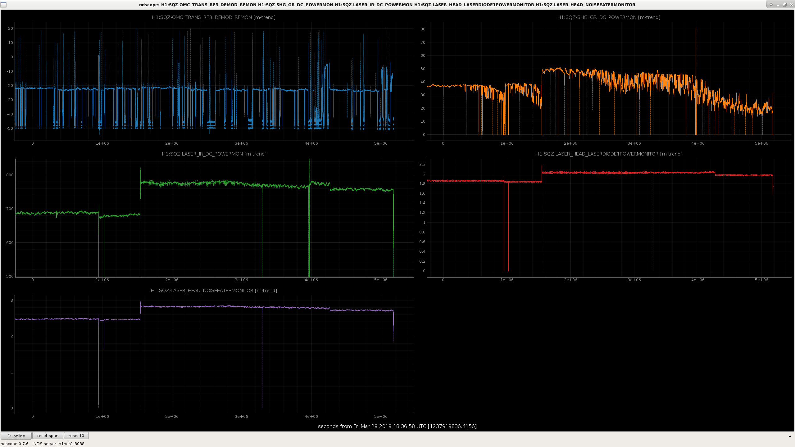
Main message: I've made another change to the squeezer laser current, which will hopefully give us a week or two without mode hopping, but it seems that we need to start planning on changing out the squeezer laser.
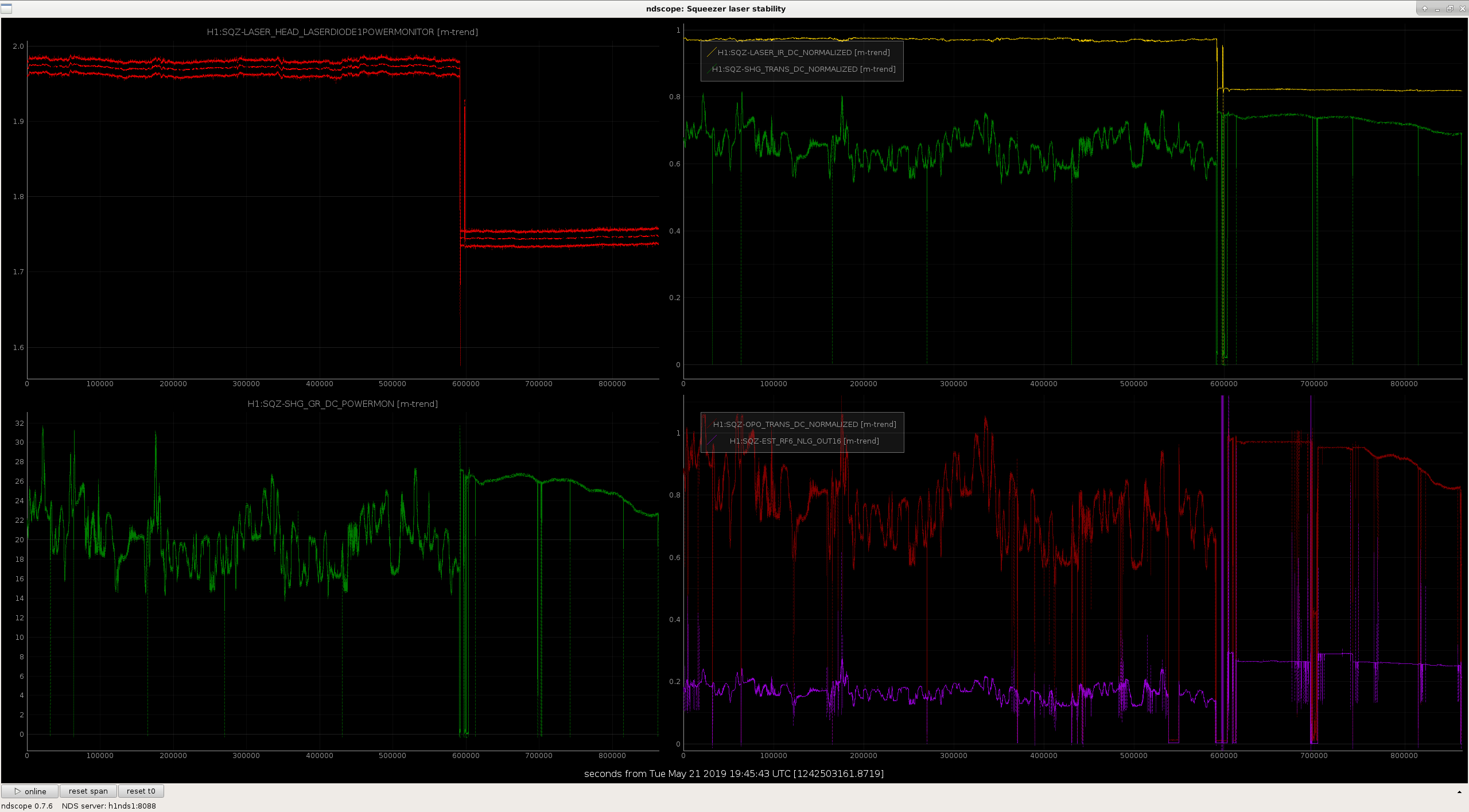
The first attachment shows a 60 day trend of the squeezer laser power, and the green power produced by the SHG degrading as the laser mode hopping becomes worse. Jeff B and I had made a small adjustment to the laser current last Friday, 49327 but this step was not large enough to fix the problem.
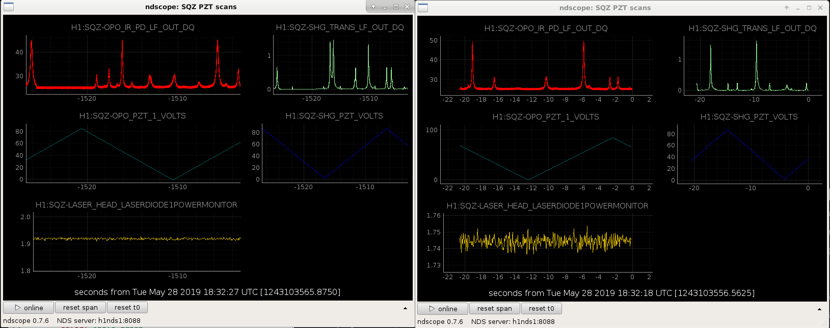
We have potentially three ways to quickly see that the laser is multi-mode, SHG scan, OPO scan, and by looking at the beatnote. Today it seemed like the OPO and SHG scans are both useful, but I could not tell the difference between the two current settings by looking at the beatnote. The second attached screenshots shows the SHG and OPO scans before and after lowering the laser current from 2A according to the laser controller to 1.857A on the laser controller. The readbacks for the laser current are consistently lower (shown in yellow in the screenshot) than the front panel readbacks. While watching both of these scans with the laser current set to the multi-mode value, I tried blocking the two main paths to see if that would change the behavoir. (While watching the SHG scan, I blocked the path which goes to the seed, clf and beatnote, saw not change in mode hopping in SHG scan. Then I blocked the SHG while watching seed scan of OPO, no change). So if the problem is due to laser feedback it is from a problem upstream of the split between the two paths, I looked through this path two weeks ago during Tuesday maintenance and again today.
This new current setting is low, which may mean that we cannot engage the noise eater with this setting. I changed the diode current nominal level to reflect the change.
A few more comments on the squeezer today:
Because the ref cav transmission was increased, there is now much more light coming to the squeezer fiber from the PSL, so I've increased H1:SQZ-FIBR_TRANS_DC_HIGH. I increased the limits on this PD, I do not think that we are in danger of saturating the beatnote diode which was why Daniel had enforced the limits in the first place (right now we have -3dBm of RF and half a mW of DC power).
The beatnote strength was initially decreased to -20dBm after I changed the laser current despite the increase in power from the PSL. I went back to the table and adjusted the alignment of the beam onto the beatnote diode, which brought the beatnote back up to -3dBm. Nutsinee had once before made a comment that changing the current on the squeezer laser seemed to change the downstream alignment, this could be consistent with that happening.
It seems that the SHG power servo has mostly been sitting at its rails for more than a week. For today I have reset the set point, so it is running. I also added a notification to the squeezer guardian that would at least tell the operators that it is railed. I think that this power stabilization would work more reliably if the laser were not running multi-mode.
The first attachment shows that the SHG power fluctuations which have been characteristic of the squeezer laser mode hopping have not returned (yet) after Tuesday's current change. The green power produced by the SHG has been dropping, along with the IR power transmitted by the SHG, but more slowly.
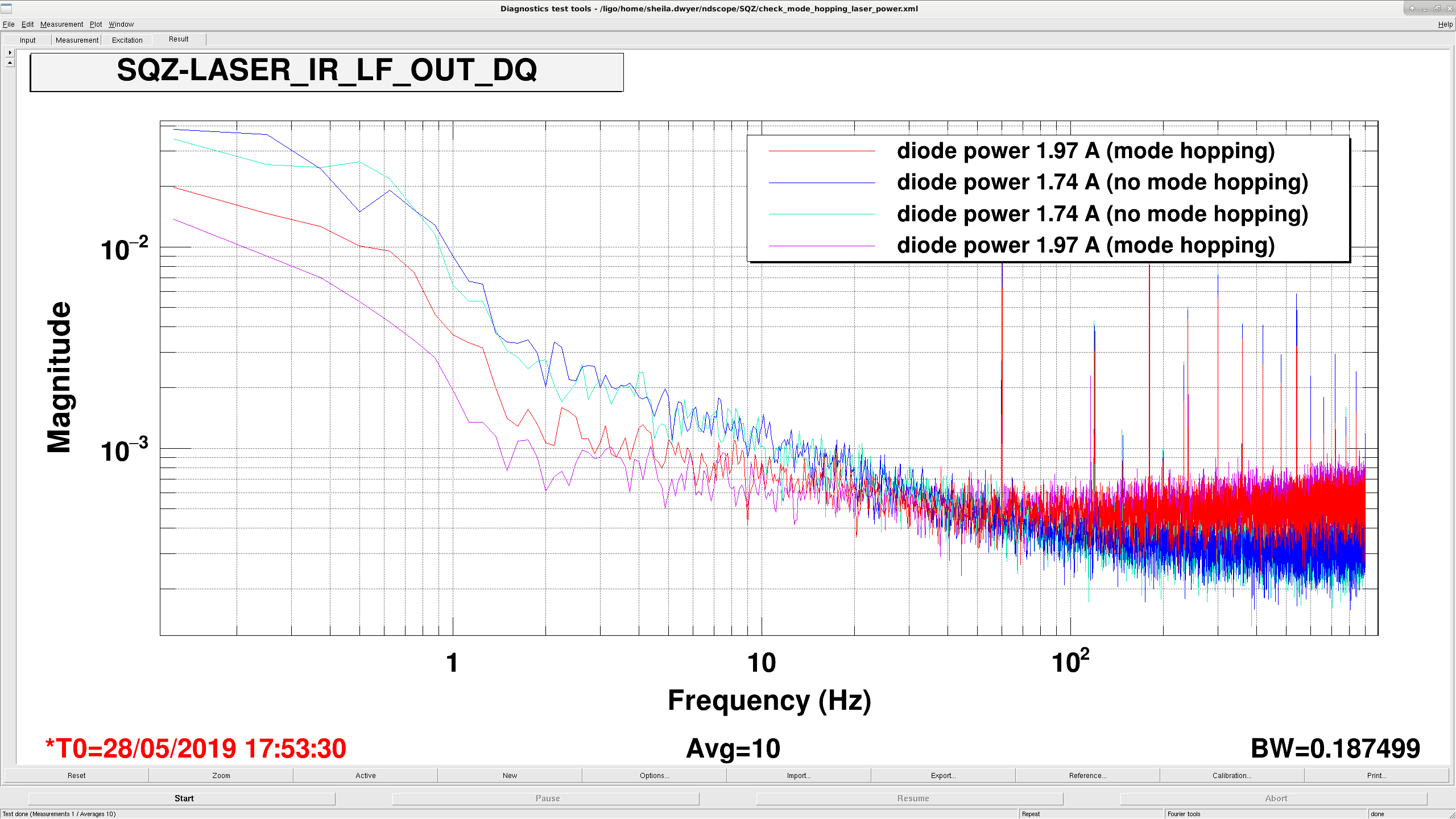
Keita suggested looking at the intensity noise out of the laser might be a usefull way to diagnose mode hopping while the cavities are blocked. The second attachment shows a spectrum from the laser power monitor diode, which is after the EOM. It does have a change in the spectrum for the low and high current times.