TITLE: 05/14 Day Shift: 15:00-23:00 UTC (08:00-16:00 PST), all times posted in UTC
STATE of H1: Earthquake
INCOMING OPERATOR: Niko
SHIFT SUMMARY:
Somewhat light Maintenance with activities finishing a little after noon.
This afternoon's issue with Initial Alignment stemmed around Input Align and having issues locking X in IR. Sadly not really sure what the issue is here.
Then there was time devoted to PRC_ALIGN in Initial Alignment to fix any issues we have been having lately (related to changes to address the ASC Yaw oscillations we've noticed the last few weeks.)
Handing off an H1 which is still trying to get locked up.
LOG:
Ops Shift Transition: 05/14/2019, Eve Shift 23:00 – 7:00 (16:00-00:00) - UTC (PT)
State of H1: Locking
Intent Bit: Commissioning
Weather: ~20 mph wind, cloudy
Primary 0.03 – 0.1Hz: 0.03 um/s
Secondary 0.1 – 0.3Hz: 0.15 um/s
Outgoing Operator: Corey
Quick Summary: Relocking after Tuesday maintenance, lost lock twice from ENGAGE_DC_VIOLINS. Commissioners on the case
As a different way of looking to see how our green Xarm and Yarms are behaving, I looked at the locked/unlocked power on the ALS refl PDs that are used for their length locking. In summary, the Xarm has a slightly deeper refl dip, but only by about 5%.
Looking at refl data from when the ALS arms were shuttered, I get a (very small) dark offset number for each arm. I then look at the value of the power on each refl diode when the green arm is flashing, versus when it is locked and well aligned.
I then look at the ratio (Locked_power + dark_offset) / (unlocked_power + dark_offset). For Yarm this value comes out to be 0.753, while for Xarm it is 0.697, indicating that the Xarm is slightly better aligned and mode matched than the Yarm, but not by so much that I'd expect such a large difference in the ease of locking the 2 arms.
Sheila, help from Marc Pirello
This morning I went to ISCT6 to look for potential laser feedback which might explain the laser difficulties we've had over the last few months (repeated mode hopping). Cleaning up a few non-dumped beams and adding a second Faraday in the SHG path doesn't seem to have fixed the power fluctations we've had.
There were some things on the table that look like potential problems (drawing here: D1201210)
Right at the output of the laser, the quarter wave plate labeled QW1A is upstream of the lens L1, which is mounted on the same base plate as HW1. The reflection off of HW1 is brighter than the other reflections (I didn't get a power measurement), and was hitting the barrel of MR1. Since this is mounted on the same base plate as the lens which I didn't want to move, I wasn't able to adjust this alignment much, but did slightly change it. This reflection was landing on a PDA100A with an ND filter on it, I am not sure why but the PDA was not powered on, so I removed it and replaced it with a razor blade.
The two rejected beams from the Faraday which go down were not dumped but hitting the table, I mounted a dump for the one on the output side of the Faraday, but there isn't a way to actually mount one for the beam on the input side which goes directly down, so I placed a razor blade on the table catching that beam.
I check that most of the power rejected by the Faraday (beam going up on the input side) was a back reflection from the SHG by blocking the path downstream in different places. Peter King helped me find a Faraday yesterday in the optics lab, with polarizers attached. While there is room to mount this Faraday between BS1 and L2, but when I placed the Faraday there everything downstream (SHG and AOMs, fiber coupling) was mis-aligned. Because I wouldn't have had time to realign all of that in the maintence window, I instead installed the Faraday in the path to the SHG only, between M22 and DS1. I had to shim the Faraday to get the height right. This reduced the beam rejected by the first Faraday to something that is not a backreflection. I realgned the SHG, and adjusted the waveplate HW9 to get the power into the SHG to match what it was before adding the Faraday (around 70mW). We must be dumping a lot of power on the Faraday dumps, so we might want to replace it with a razor blade.
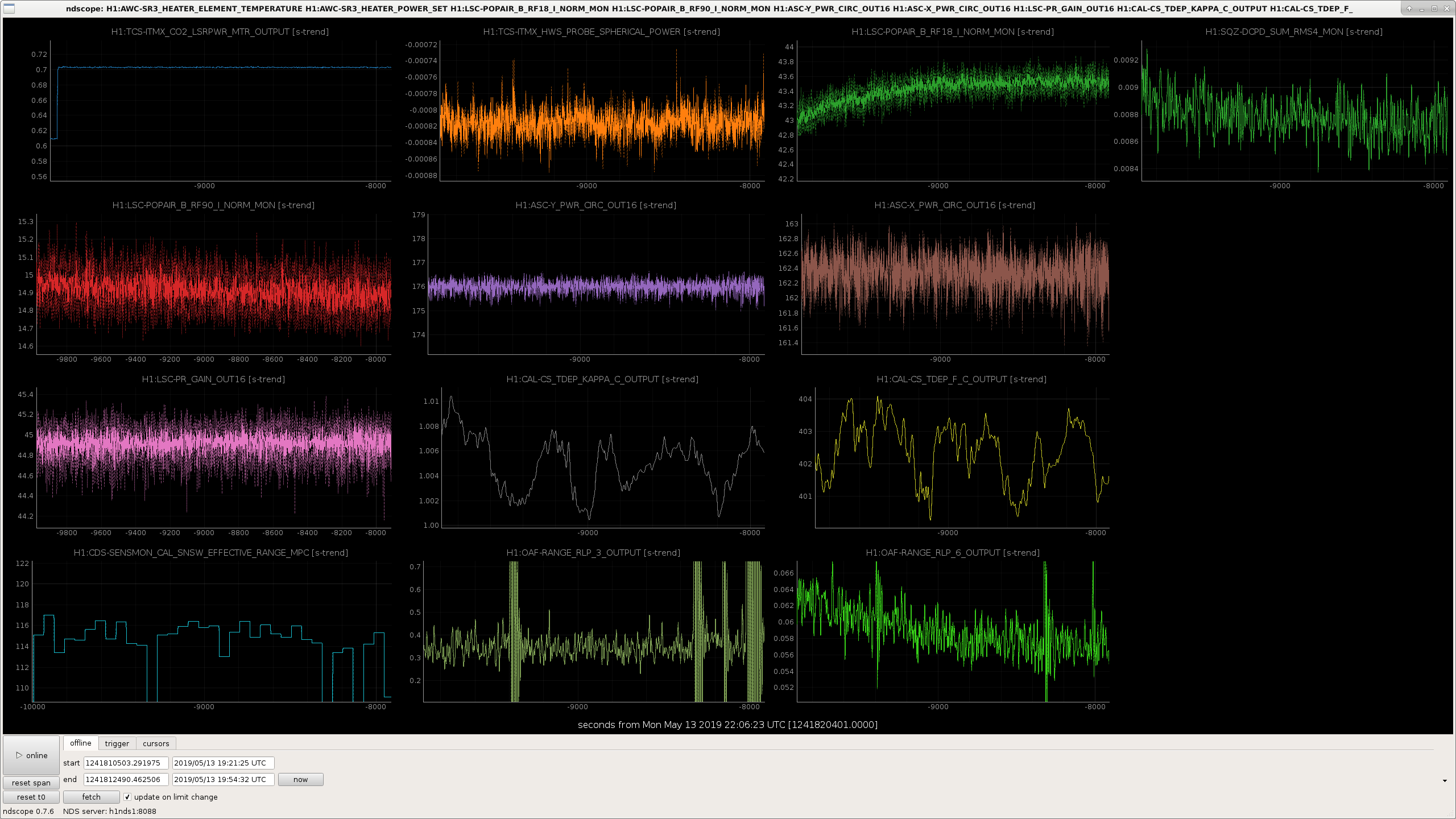
The attached screenshot shows the symptom that we are hopping to address by getting rid of possible laser feedback. At around -3e6 seconds in the attached screenshot and at around -2.6e6 seconds the laser current was adjusted to avoid mode hopping and each time the green power became more stable for a few days (weeks) before it became unstable again. When we have adjusted the laser current, we have been watching for mode hopping by scanning the SHG, where we can see the additional mode come and go as the current is changed. Today I didn't see evidence for mode hopping when scanning the SHG. It does not look like my work has resulted in a more stable green power, so as far as that is a reliable diagnostic of the laser problems, this hasn't fixed the problems.
Georgia, Sheila, Jenne
Operators have been noting that PRC align hasn't worked in the last few days. PRX was locking OK in length, but as soon as the alignment loops from REFL WFS to PRM came on the cavity would unlock. We were using REFLA9Q for the PRM sensor in this state, but we rephased these WFS on Friday (49172).
We looked at REFL, POP and AS WFS while moving PRM, and found that REFLB9 had less noisy signals than A for both pitch and yaw, however the zero crossing of REFL B Y was not maximizing the POP build up. We changed the pitch sensor to REFLB9I and the yaw sensor to REFLA9I, and reduced the gain for both pitch and yaw. This is in the ALIGN_IFO guardian now, and worked fine the one time that we ran through it.
During maintenance today, in an effort to center our green input pointing QPDs that sit on TMSY, I pico-ed the M3 mirror since it is the only one that controls a green beam only, and not any IR beams. However, it is not the beam that goes to the QPDs, but rather is the beam that goes to the ETM. I tried to undo my pico moves, but as always, it won't be perfect since they are hysteretic. So far we've been able to do initial alignment okay, so hopefully things will be smooth for the rest of acquisition.
After I put the picos back, Sheila and I ran the green arm with WFS feedback to ETMY and TMSY, and moved the digital offsets on the green QPDs, and didn't find that any of the offsets made a major change in the amount of light transmitted through the arm cavity or in the amount of light reflected to the length locking photodiode. Changing the QPD A offset in yaw made the biggest change, but it still only decreased our transmitted power by about 1%. We think that when the green Y arm is flashing, more than 20% of the power is in the non-00 mode, so if this was due to clipping we'd expect that we'd be able to change the QPD offsets and find a place where we had a significantly different amount of power transmitted. So, it seems that clipping is not the reason that we struggle to lock the Yarm in green more than the Xarm in green.
After we changed the SEI configuration Guardian nodes to work with the new Fader from B. Lantz (see my alog46297), Jim and I had waited to see how the fader would handle during a lock before automating SC changes in the case of an issue with the BRS. Changing the SC with the fader while in lock has proved to be very successful so I wrote up new code for ETMY_ST1 and ETMX_ST1 SC Guardian nodes.
These nodes watch the BRSX_STAT and BRSY_STAT nodes to see if they are are in the FAULT or DAMPING_HIGH_VEL states. If one of these monitor nodes goes into either of these states, then it will fade off the sensor correction for that cucumber chamber until the monitor node is okay again while it waits in the BRS_FAULT_SC_OFF state. Or, if the SC node is transitioning to a state that uses a BRS corrected SC and the stat node is not okay, then it will wait in the BRS_FAULT_SC_OFF state until it is resolved.
The circumstances for the BRS stat nodes to go to either fault state are very uncommon, so we should rarely see this. The reason to automate this process is because if the BRS is feeding a signal to the ISI that is not healthy, we will most likely lose lock.
I tested it out today and all seemed to work as expected. I created a new brs_states.py that will import the normal states.py that every other SC node uses. This allows the state creation to stay automated, while giving users freedom to change/add configurations easily. The brs_states.py adds a new state (BRS_FAULT_SC_OFF) and adds a decorator to the idle states that use a BRS sensor corrected signal. I attached the code if anyone is interested.
(Edited typo)
WP 8204
Continuing with work done last week (alog 49072) replaced Gige camera for ITMY Red. This corresponds to MEDM ITMY Cam23 which has been nonoperational for some time. Camera might need to be realigned.
CER
ITMY Green (camera 24) connects to network switch port 38
ITMY Red (camera 23) connects to network switch port 40
LVEA
ITMY Green (camera 24) connects to port 1 in LVEA junction box
ITMY Red (camera 23) connects to port 2 in LVEA junction box
We are mostly recovered from maintenance, and started alignment for the arms.
Remain with green arms locked for investigations into y-arm clipping (Jenne et. al).
Swept the LVEA. Unplugged phone and removed batteries from south bay phone behind storage racks.
Swept EXVEA earlier today as well. All good.
I reset both PSL power watchdogs at 17:48 UTC (10:48 PDT). This completes FAMIS 10710.
Peak power: 220 uW
I measured the output from the fiber launcher at EX. I placed a Thorlabs S302C power sensor head about 4in from the end of the launcher, after the lens translation stage. The power range for this head starts at 100uW, so it should be okay. I left the iris on the launcher as we nominally run it (6mm as read from the iris). With the iris fully open, it was too large to fit in the sensor head that I had with me, so I will have to revisit that another maintenance day.
It looks like my disk access speed testing is to blame for the jumps in the disk usage. The tests created a 1GB file every 5 minutes, and sometimes it came into sync with the hourly ZFS snapshots, resulting in jumps in the size of the ZFS snapshots over the past two weeks.
We have manually destroyed some early May snaps on h1fs0 (and h1fs1) which has freed 26GB immediately and will free up more space as the large snapshots roll off the look backup period.
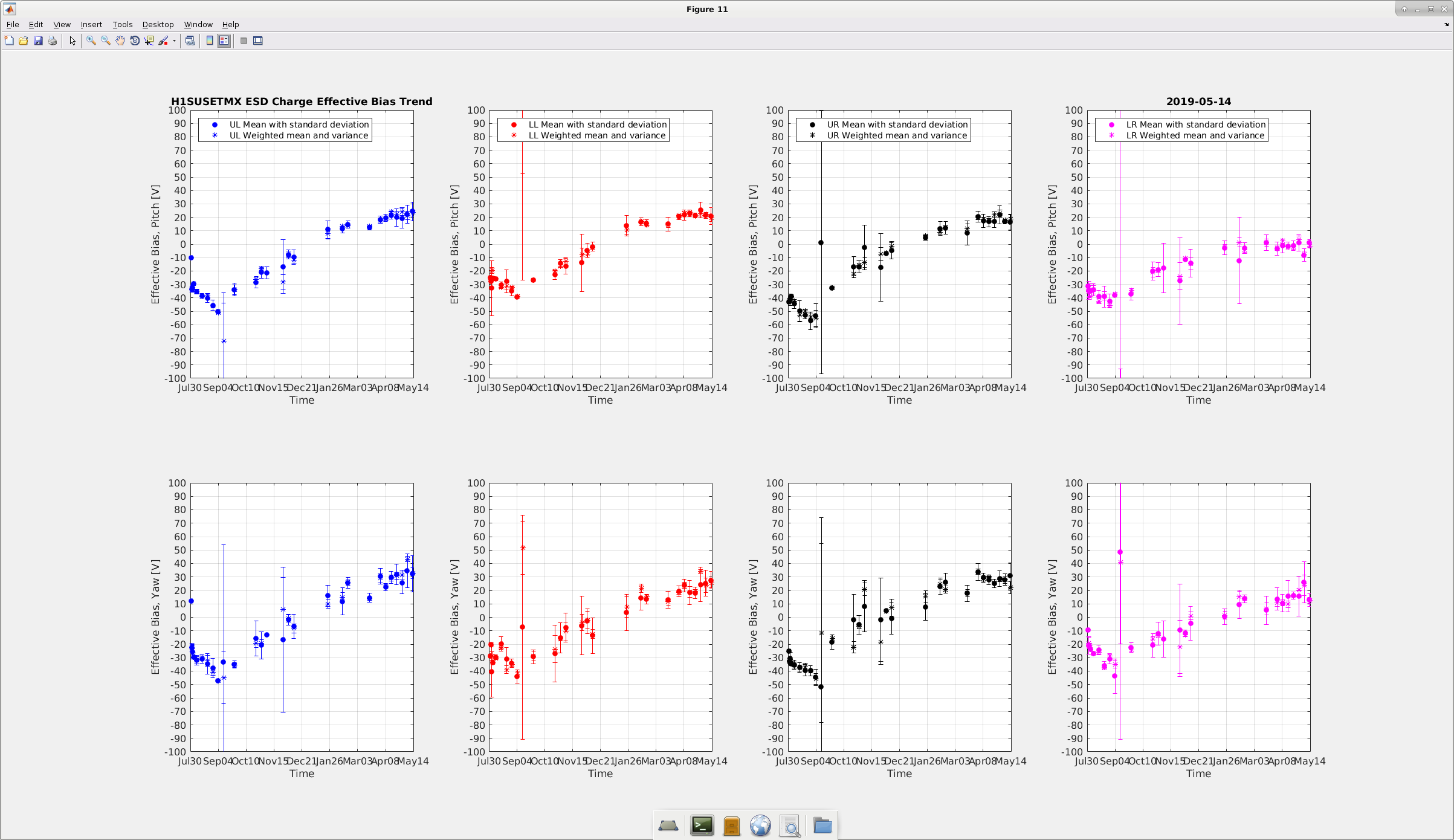
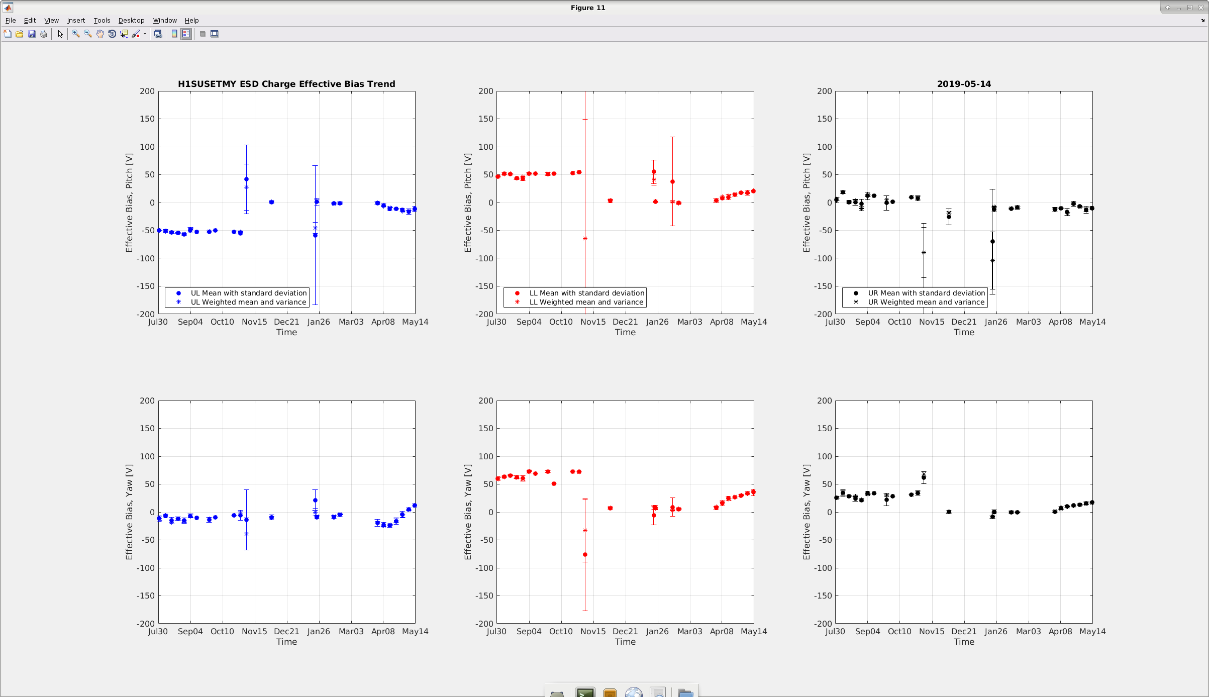
Results/plots for the OPLEV charge measurements for the ETMX and ETMX are attached below. At the ETMX the effective bias for all four quadrants is between 0-20V for the pitch and around 20-30V for the Yaw. At the ETMY it is around 10-20 V, except for the Yaw which is inching towards 40V.
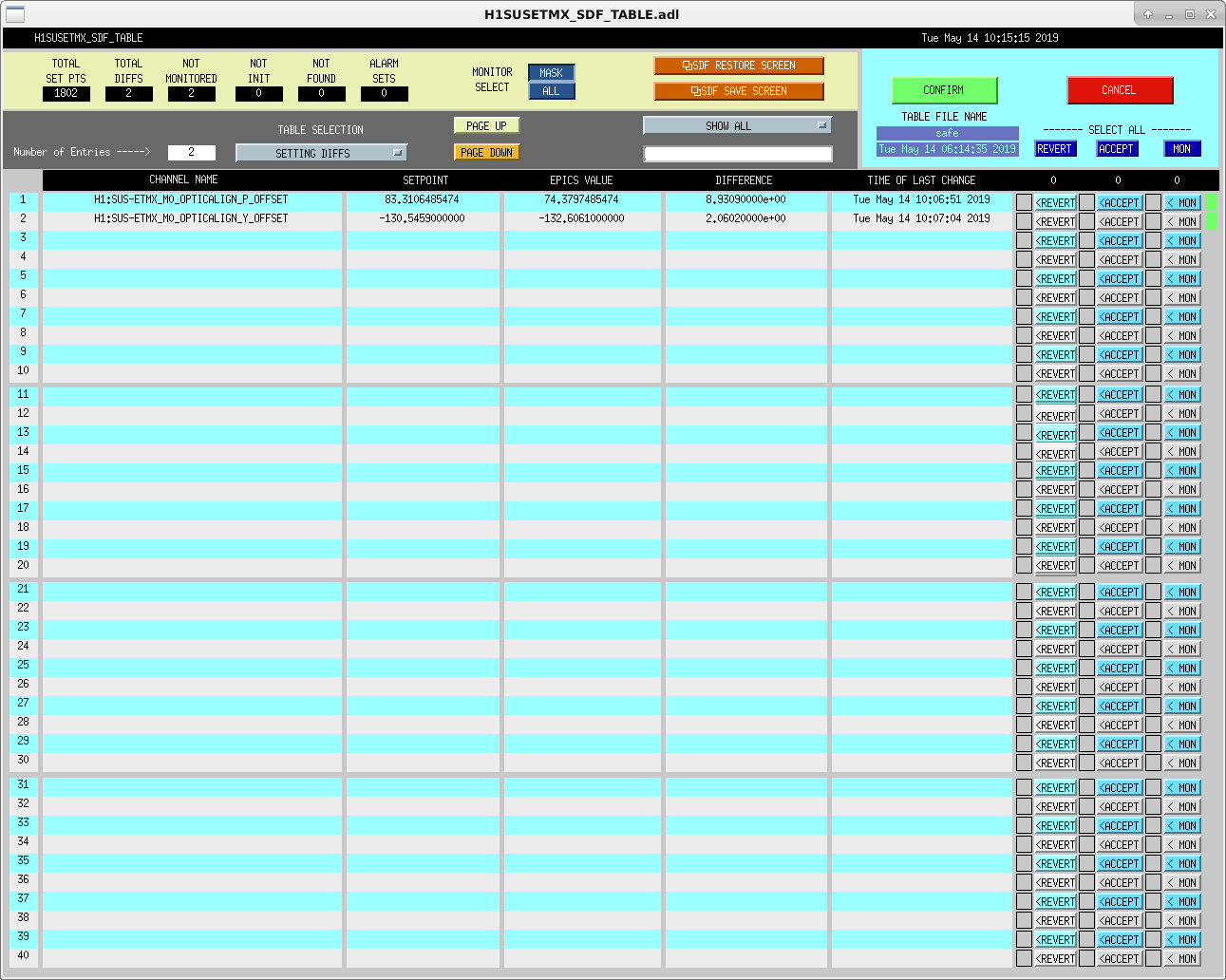
All the values were restored to its original after the measurements were completed. However, for optic align slider values, SDF differences (screenshot attached) are flagged up (for both ETMX and ETMY) which I am not sure why and this hasn't happened before. Having a look at the ndscope and going back in time, I see no difference in my restored values and the ones during the IFO lock.
Hugh & Jeff B., Checked the dust monitor vacuum pumps. Adjusted the vacuum pressure at End-Y; all others were within spec. All pump temperatures are within spec. There is a bit of carbon build up on the exhaust muffler on the End-Y pump. Will continue to monitor this pump for a future rebuild. Closing FAMIS #12987
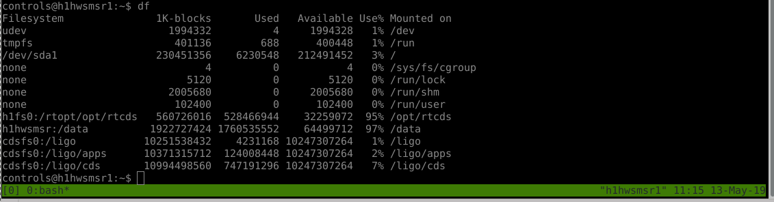
Since Saturday the /opt/rtcds file system usage shot up from 91% to 99%. I'm working on freeing up space and figuring out what is taking this space.
Please do not create any large files under /opt/rtcds until I have freed up space.
Sheila, Georgia
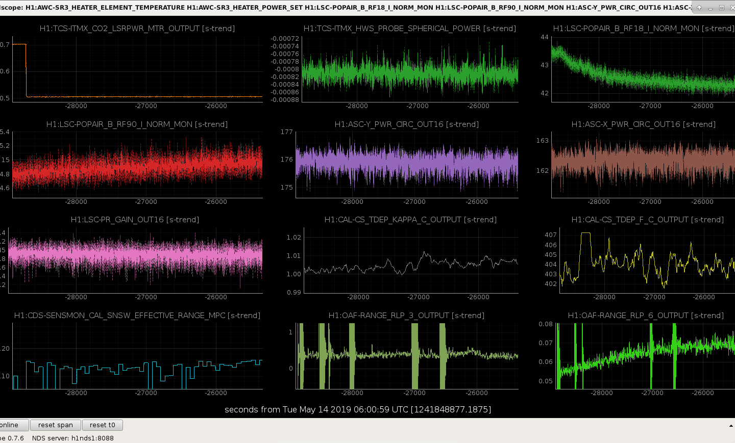
Today, in preparation for a possible input power increase later this week, we tried to optimise some of our TCS settings. Following on from previous CO2 steps, we took a small 100mW step up in CO2X power (to 700 mW), expecting the frequency noise coupling to improve like last time. What we saw was:
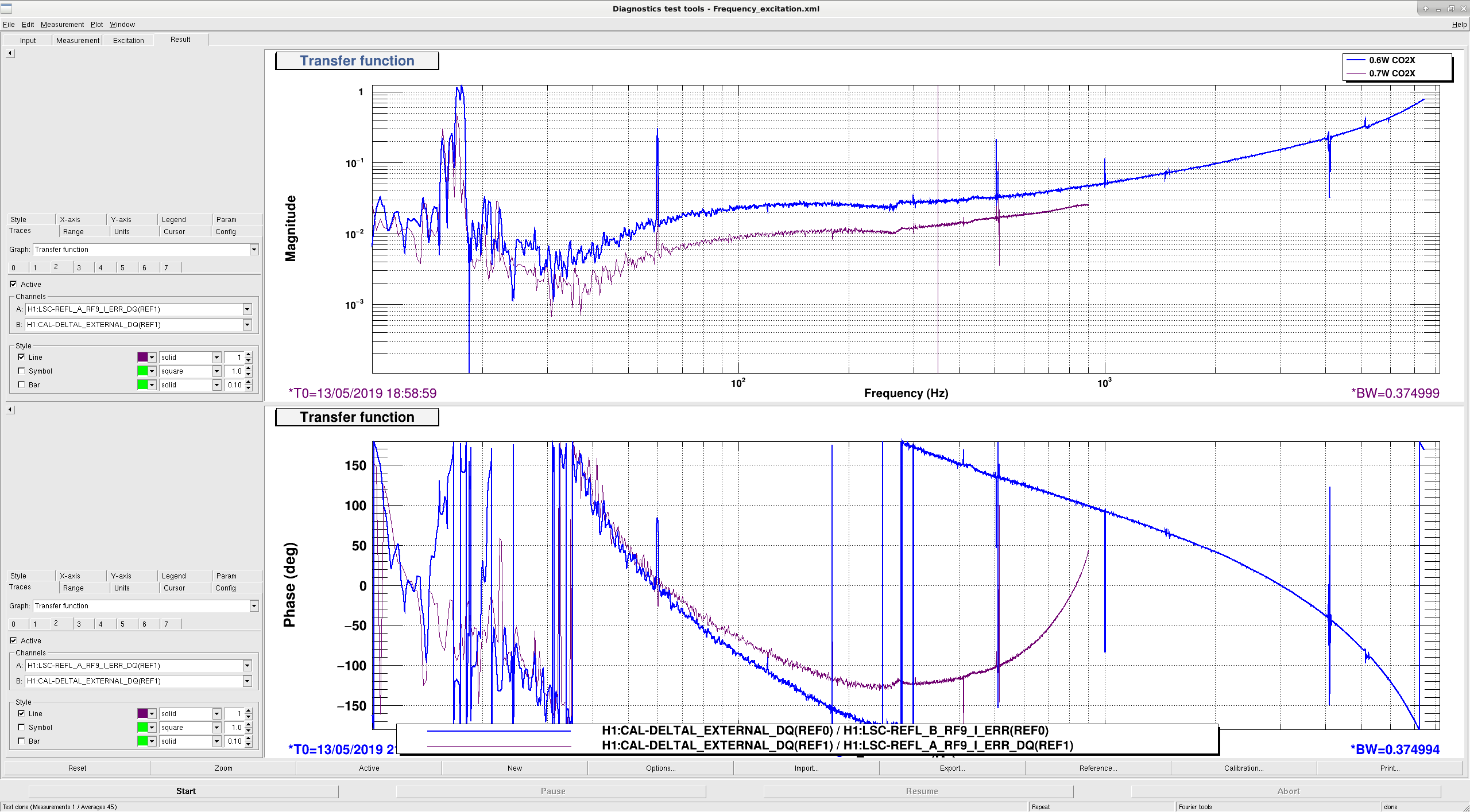
The time series of several diagnostics is shown in the first attachment. (Edit: removed comment about kappa_c and fc since we can't really tell if they are changing). Perplexingly, this is the opposite of what happened when CO2X was last increased. Since then we have change SR3 heater, and the spot positions. I'm also confused about how the frequnecy noise coupling (measured with the noise budget injections) got worse while the BLRMS improved. (edit: see sheila's comment)
Given the frequency noise coupling we decided to then decrease the CO2 power to 500 mW (100 mW less than nominal), and saw the opposite of the effect listed above (second attachment). I think we did not get a chance to remeasure the frequency and intensity noise coupling before losing lock though.
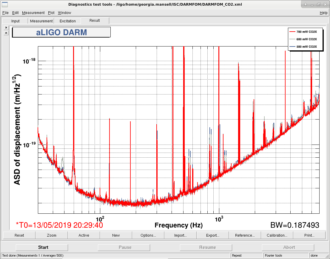
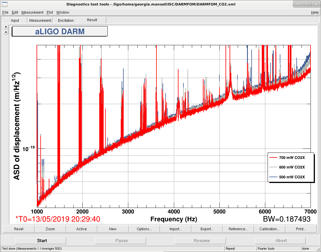
I had a look at some DARM spectra with 500 averages (third & fourth attachments), and it looks like the high frequency noise shows opposite behaviour to the frequency noise coupling we measured. Based on the DARM spectra and buildups I'd suggest we should increase the CO2X power. For now it is back to the nominal 600 mW.
Yesterday I plotted the measured noise coupling inverted, and gave Georgia wrong information about which way couplings changed.
It turns out that the Frequency noise and intensity noise couplings to DARM both decreased with increase CO2 power on CPX, which was the expected result. So it seems like we could change the set point for CO2X to be 0.7W.
TITLE: 05/13 Day Shift: 15:00-23:00 UTC (08:00-16:00 PST), all times posted in UTC
STATE of H1: Observing at 112Mpc
OUTGOING OPERATOR: Cheryl
CURRENT ENVIRONMENT:
Wind: 4mph Gusts, 3mph 5min avg
Primary useism: 0.03 μm/s
Secondary useism: 0.32 μm/s
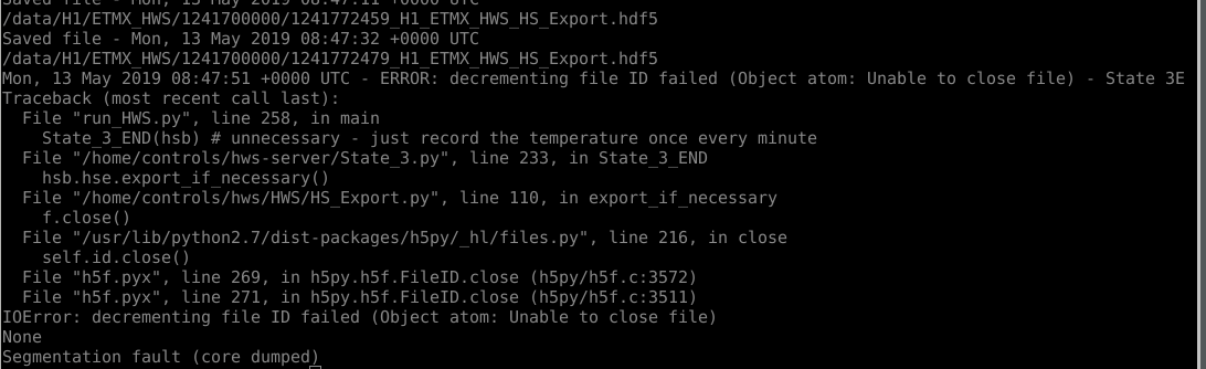
QUICK SUMMARY: Lock is 15+ hours old. HWS code for ITMy, ETMx, and ETMy has stopped according to DIAG_MAIN.
I have done the following:
h1hwsmsr, h1hwsmsr1, h1hwsex, h1hwsey),tmux attach)thin)
python run_HWS.py -c {0/1} where IY EX and EY are 0, and IX is 1)I'm not sure if this was the right thing to do; let's see if this keeps it alive during today's CO2 test.
I ran the thinning scripts for all 4 camera directories. ITMY seemed to remove the most by far. We are now at 82% capacity on /data
I am in the process of making a script to automate the thinning and checking that the files were backed up, but until then we will need to keep an eye on this.
M. Pirello, D. Gustafson
We installed new v3 Baluns on the following signals in the CER:
ISC-C3(37-1) 40Mhz TCS AOM Return exchanged v1-117 with v3-S002
ISC-C3(33-4) 158.8Mhz Fiber Beat Note Return exchanged v1-193 with v3-S003
ISC-C3(33-5) 79.4Mhz SQZ VCO Return exchanged v1-151 with v3-S004
ISC-C3(33-6) 203.125MHz SQZ VCXO Return exchanged v1-052 with v3-S005
ISC-C4(39-3) 79.4MHz PSL VCO Return exchanged v1-093 with v3-S010
These are all return signals, the impact should be minimal. Work was completed per WP8150
Balun status can be seen here E1900100.
Continuing the Balun exchange program:
We installed new v3 Baluns on the following signals in the CER:
ISC-C4(39-1) 79.4MHz "ALS DIFF VCO Return" exchanged v1-102 with v3-S006
ISC-C4(39-2) 79.4MHz "ALS COMM VCO Return" exchanged v1-094 with v3-S068
ISC-C4(26-2) 45.5MHz "PEM Readback for Antenna Demod" exchanged v1-055 with v3-S009
ISC-C4(19-8) 9.1MHz "PEM Readback for Antenna Demod" exchanged v1-147 with v3-S116
Work was completed per WP8190. WP was modified to reduce impact to the IFO during this weeks maintenance, we did not touch squeezer.
Continuing the Balun exchange Program:
We installed new V3 baluns on the following 45MHz signals in the LVEA:
ISC-R1 (41-6) 45MHz Auxiliary Modulation (EOM Driver) exchanged v2-DG146 with v3-S152
ISC-R2 (41-2) 45MHz Distribution exchanged v2-DG083 with v3-S094
ISC-R3 (41-3) 45MHz Distribution exchanged v1-145 with v3-S117
Work was completed per WP8200, balun status can be seen here E1900100.
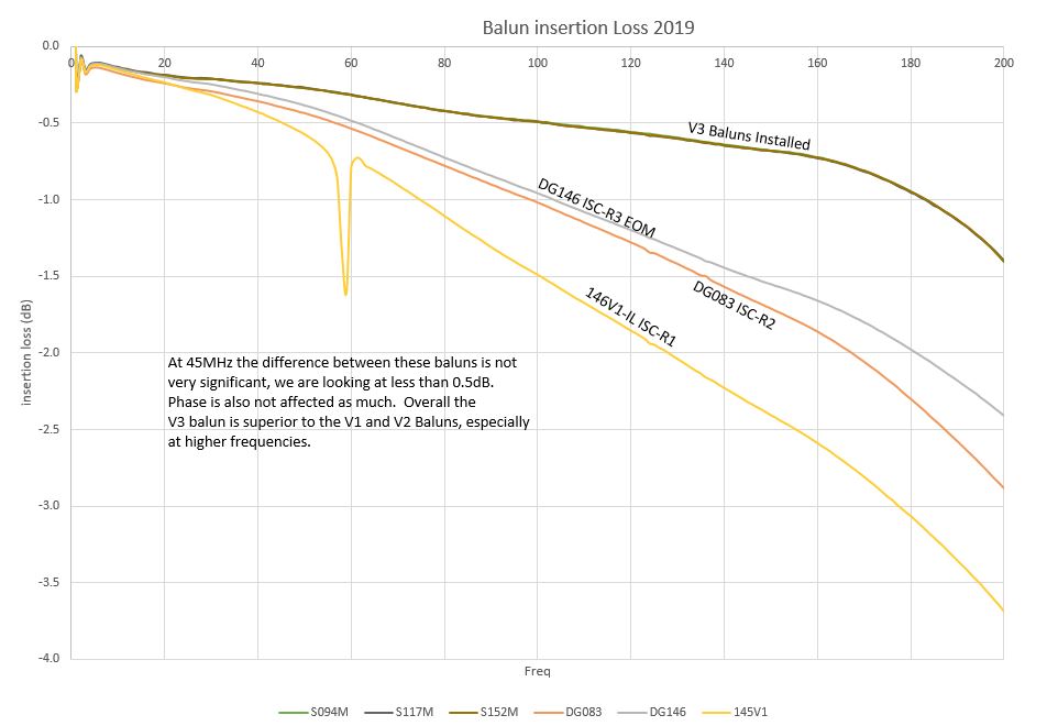
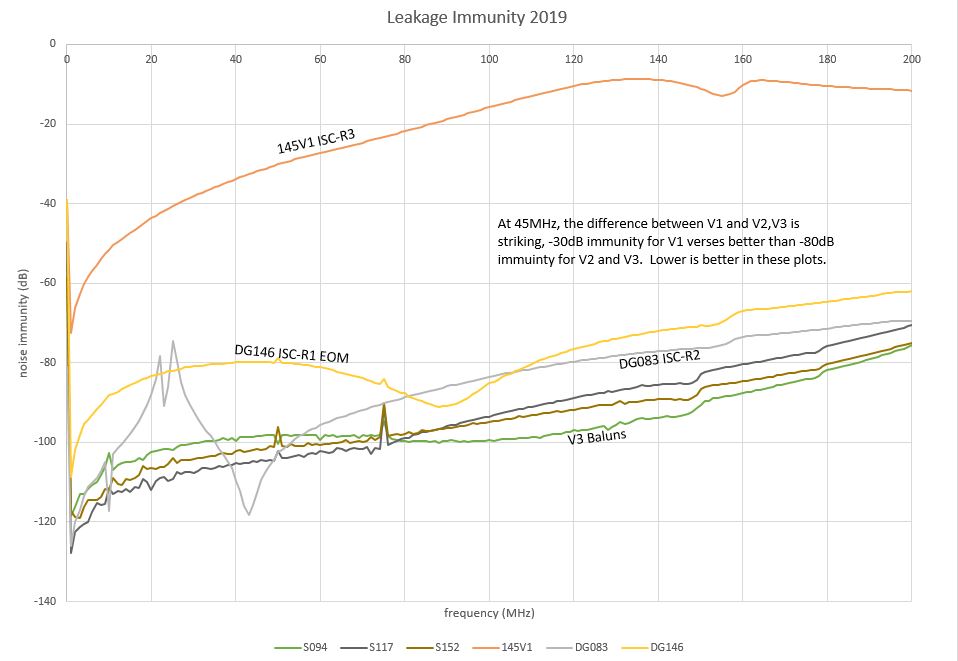
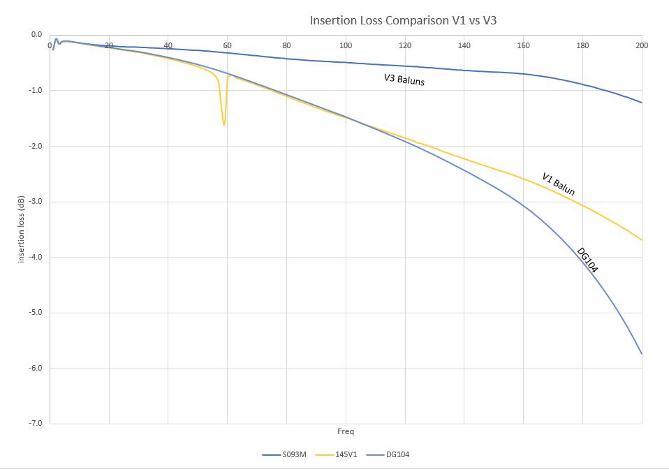
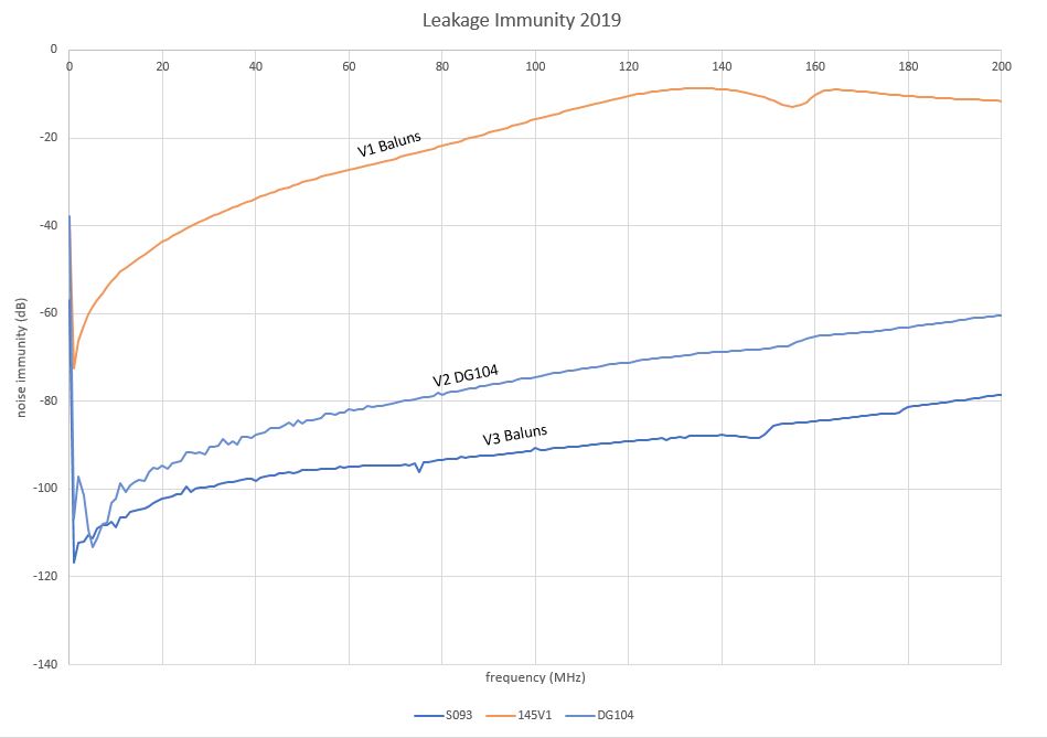
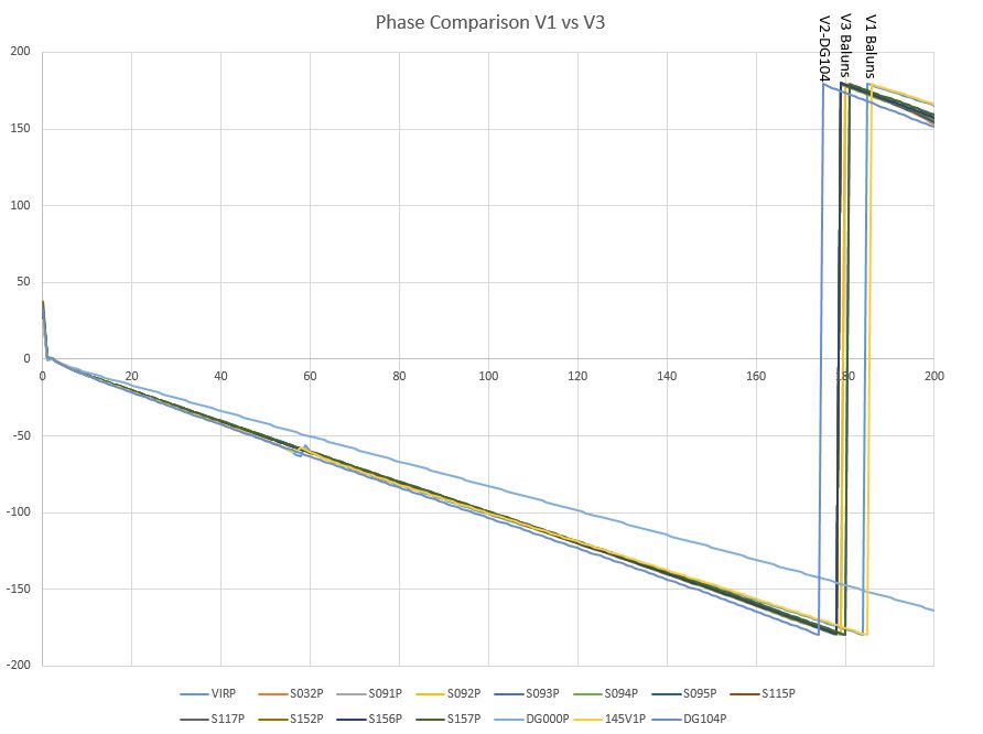
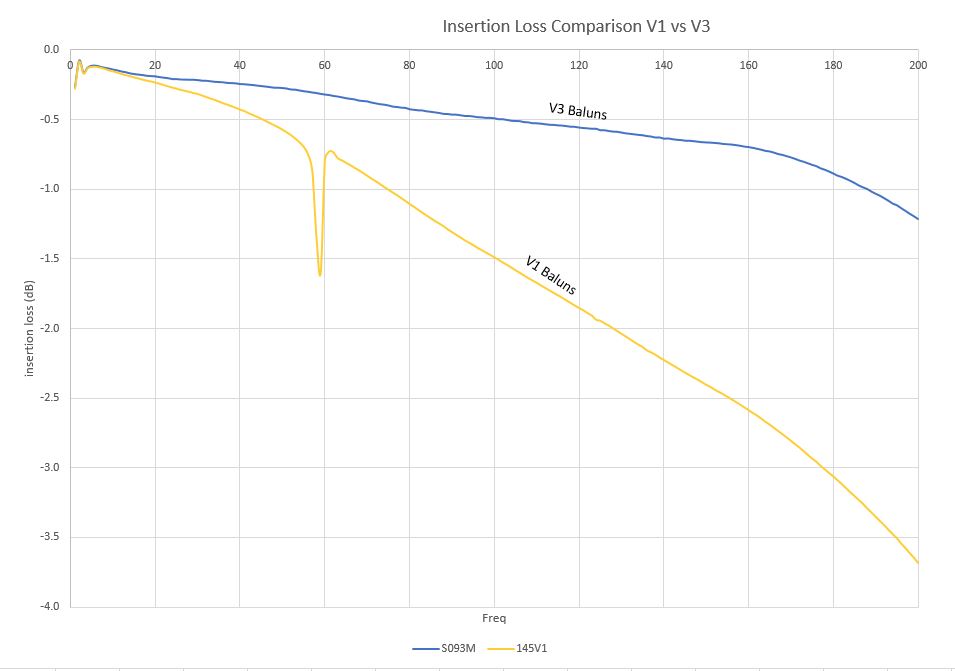
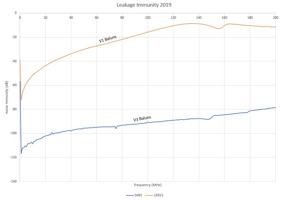
I have attached Insertion Loss and Leakage scans from the old baluns as well as the new ones.
M. Pirello, D. Gustafson
Continuing the Balun exchange Program:
We installed new v3 baluns on the following signals at the PSL racks and at HAM6:
PSL-R2 (18-2) ISS AOM 80MHz exchanged DG-104 with v3-S069
ISC-R3 (41-2) Distribution 4th Harmonic exchanged v1-053 with v3-S160
ISC-R3 (41-4) Distribution 8th Harmonic exchanged v1-091 with v3-S040
ISC-R3 (39-4) Distribution 42.2MHz exchanged v1-125 with v3-S060
Work was completed per WP8215, balun status is in the same place it was last week, E1900100.
Attached is a comparision between the balun modified by hand (DG-104), and the new v3 balun which replaced it.
M. Pirello, P. King, D. Gustafson
Continuing the Balun exchange Program:
We installed new v3 baluns on the following signals at the PSL racks:
PSL-R2(17-1) FSS Modulation exchanged v1-043 with v3-S157
PSL-R2(17-2) FSS exchanged v1-014 with v3-S093
PSL-R2(17-4) PMC Modulation exchanged v1-021 with v3-S115
PSL-R2(17-5) PMC exchanged v1-050 with v3-S156
PSL-R2(17-6) Injection Locking exchanged v1-084 with v3-S095
ISC-R1(41-2) Distribution JAC Future exchanged v1-159 with v3-S092
** On the last one, the labels on the feed through may be more correct than the DCC. I followed the cable path to the ALS VCO for the PSL.
If it is the ALS VCO, Peter told me that it is possibly 80MHz and in this case the difference between V1 and V3 is about 0.75dB more power, and no measurable difference in phase. The PSL signals being under 45Mhz should be less than 1 degree difference in phase, and less than 0.25dB difference in power.
Work was completed per WP8208, balun status is in the same place it was last week, E1900100.
I have attached insertion loss and leakage scans of v1 vs v3 baluns.
We checked the ISC-R1 (41-2) Balun and determined this signal is the REFL_B demod, 9MHz. There should be very little phase & power difference between V1 and V3 baluns at this frequency.
M. Pirello, D. Gustafson
Continuing the Balun exchange Program:
We installed new v3 baluns on the following signals at the end stations.
EX-ISC-C1 (41-5) Return PLL Beat Note 39.5MHz exchanged v1-176 with v3-S050
EX-ISC-C1 (41-6) Return ALS Laser VCO 79.4Mhz exchanged v1-049 with v3-S042
EX-ISC-R1 (41-1) ALS Laser VCO 71MHz exchanged v1-189 with v3-S114
EX-ISC-C1 (41-5) Return PLL Beat Note 39.5MHz exchanged v1-137 with v3-S041
EX-ISC-C1 (41-6) Return ALS Laser VCO 79.4Mhz exchanged v1-199 with v3-S155
EX-ISC-R1 (41-1) ALS Laser VCO 71MHz exchanged v1-039 with v3-S059
Work was completed per WP8222, balun status is in the same place it was last week, E1900100.
M. Pirello, D. Gustafson
Continuing the Balun exchange Program:
We installed new v3 baluns on the following signals at the Squeezer
ISC-R3 (39-1) 80MHz SQZ EOM (OPO) exchanged v1-178 with v3-S082
ISC-R3 (39-2) 35.5MHz SQZ EOM (SHG) exchanged v1-060 with v3-S089
ISC-R3 (39-3) 200MHz SQZ EOM (CLF) exchanged v1-166 with v3-S031
SQZ-R1 (41-1) 80MHz OPO Demodulation exchanged v-122 with v3-S084
SQZ-R1 (41-2) 35.5MHz SHG Demodulation exchanged v1-020 with v3-S033
SQZ-R1 (39-3) 71MHz SQZ VCO Laser Locking exchanged v1-190 with v3-S083
Work was completed per WP8230, balun status is in the same place it was last week, E1900100.
** The 200MHz SQZ EOM CLF signal may require a slight phase change, about 8 degrees difference and 2dB more power with the V3.
M. Pirello, D. Gustafson
Continuing the Balun exchange Program:
We installed new v3 baluns on the following signals at the Squeezer and the PSL racks:
SQZ-R1 (41-3) 3.125MHz SQZ Angle Demodulation exchanged v1-171 with v3-S108
SQZ-R1 (41-4) 3.125MHz SQZ Angle Demodulation exchanged v1-145 with v3-S109
SQZ-R1 (41-5) 6.25MHz CLF Demodulation exchanged v1-183 with v3-S085
ISC-R1 (41-1) 71MHz Distribution exchanged DG-02 with v3-S086
ISC-R1 (41-3) 15th Harmonic Modulation exchanged DG-01 with v3-S058
TCS-MEZ (41-1) TCS exchanged v1-153 with v3-S079
Work was completed per WP8240, balun status is in the same place it was last week, E1900100.
M. Pirello, D. Gustafson
Continuing the Balun exchange Program:
We installed new v3 baluns on the following signals at the field racks near the PSL:
ISC-R2 (41-1) 9MHz Distribution exchanged v1-047 with v3 S019
ISC-R2 (41-3) 2nd Harmnonic Distribution exchanged v1-098 with v3-S019
ISC-R2 (41-4) 3rd Harmonic Distribution exchanged v1-157 with v3-S015
ISC-R2 (41-5) 10th Harmonic Distribution exchanged v1-179 with v3-S016
ISC-R2 (41-6) 15th Harmonic Distribution exchanged v1-074 with v3-S132
ISC-R1 (41-4) 24MHz MC Distribution exchanged v1-040 with v3-S017
ISC-R1 (41-5) 9MHz Main Modulation exchanged v1-033 with v3-S018
Work was completed per WP8244, balun status located at this link: E1900100. This concludes all "known" balun work at the corner station. We are sprinting to next week where we intend to replace the remaining twelve v1 baluns at the end stations.
M. Pirello, D. Gustafson
Continuing the Balun exchange Program, we installed new v3 baluns on the following signals at both end stations:
EX
ISC-R1 (41-2) 24.4MHz Modulation exchanged v1-022 with v3-S074
ISC-R1 (41-3) 24.4MHz Demodulation exchanged v1-184 with v3-S131
ISC-R1 (41-4) Not Connected exchanged v1-064 with v3-S078
ISC-R1 (39-1) 24.4 WFS A Demod exchanged v1-077 with v3-119
ISC-R1 (39-2) 24.4 WFS B Demode exchanged v1-026 with v3-S076
ISC-R1 (39-3) 71 CPS Timing Fanout exchanged v1-059 with v3-S020
EY
ISC-R1 (41-2) 24.4MHz Modulation exchanged v1-127 with v3-S073
ISC-R1 (41-3) 24.4MHz Demodulation exchanged v1-118 with v3-S011
ISC-R1 (41-4) Not Connected exchanged v1-013 with v3-S012
ISC-R1 (39-1) 24.4 WFS A Demod exchanged v1-126 with v3-S075
ISC-R1 (39-2) 24.4 WFS B Demod exchanged v1-161 with v3-S013
ISC-R1 (39-3) 71 CPS Timing Fanout exchanged v1-191 with v3-S135
Work was completed per WP8255, balun status located at this link: E1900100.
** In the process of walking through the LVEA we found 4 more Baluns hidden among the TCS and SUS racks which need upgrading. We were able to upgarde one of these with this Tuesday, and will finish the remainder next maintenance day.
SUS-R3 (40-1) CPS HAM 71MHz exchanged v1-011 with v3-S113
This additional work was started per WP8261
M. Pirello, H. Radkins
The final three baluns were exchanged at the corner this morning for a total of 64 baluns replaced over 14 weeks.
TCS-R2 (41-1) 71Mhz CPS Timing exchanged v1-088 with v3-S144
TCS-R2 (41-2) N/A Empty signal with Balun exchanged v1-081 with v3-S001
TCS-R1 (41-6) TCS Signal from Mechanical Room exhcnaged v1-143 with v3-S045
All work finished per WP8261. This completes work done per FRS9794 and ECR-E1700404 at LHO.