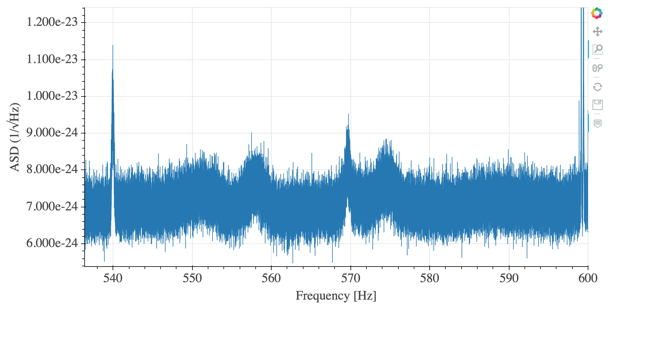
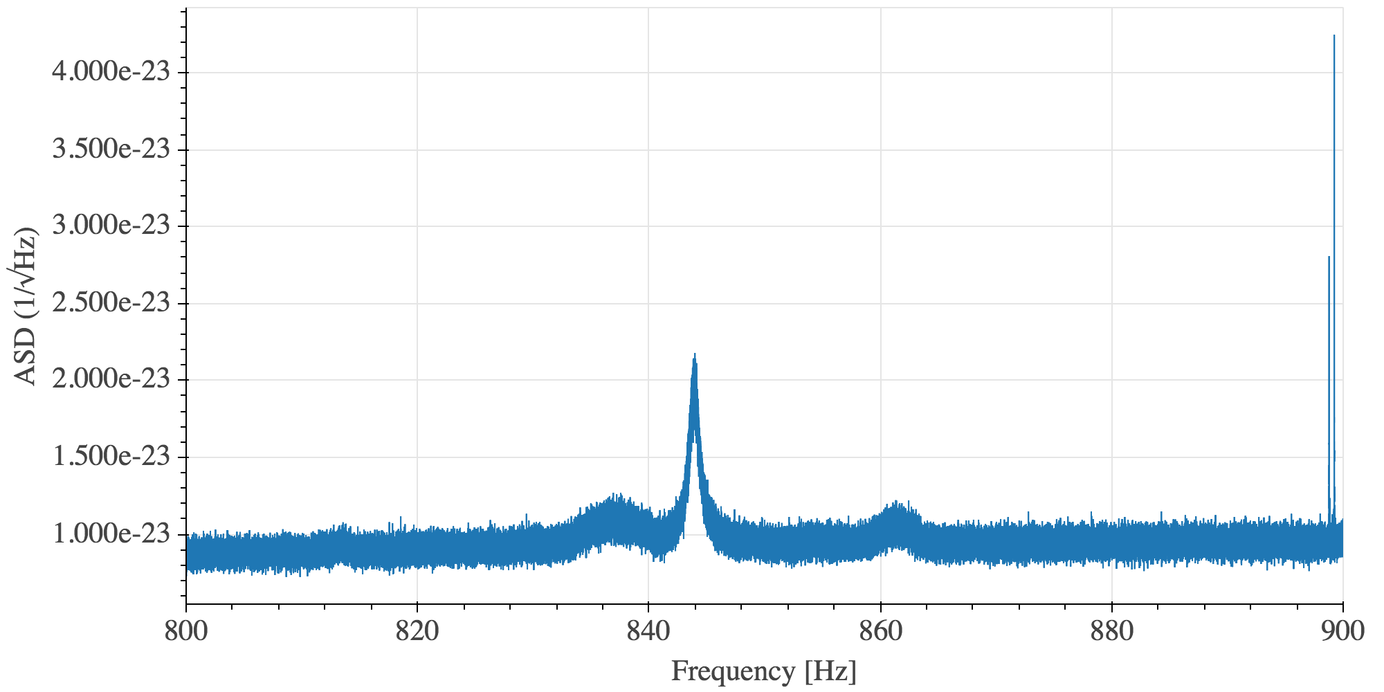
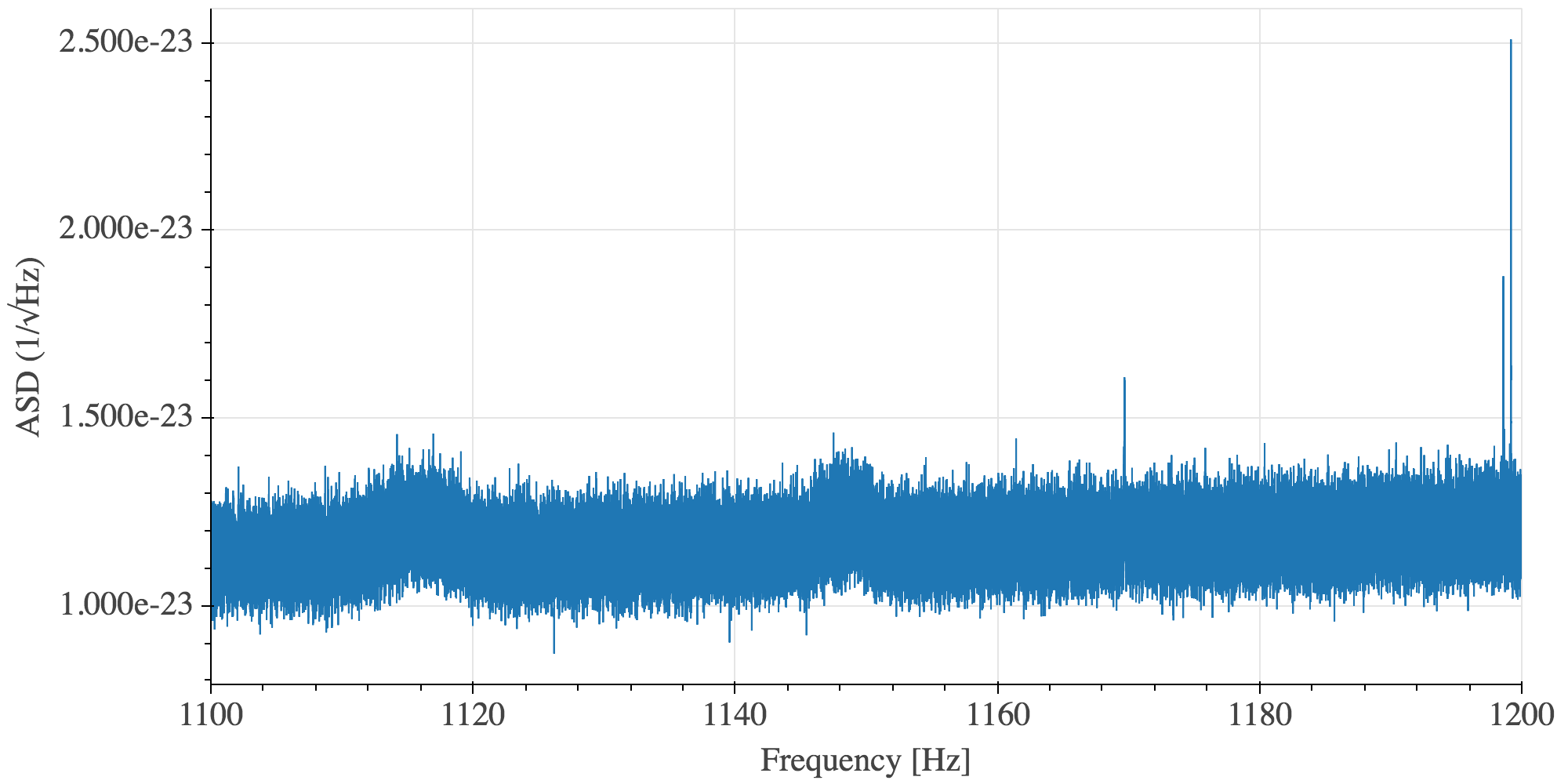
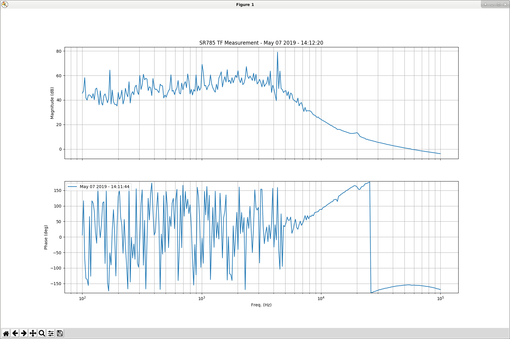
With the lower noise seen in CARM, we can now see clear coherence of some higher frequency lines with DARM. The frequencies are centered at 556, 574, 835, 860, 1115 and 1148 Hz, but are not very high Q. The third set of twin lines looks like a straight harmonics of the first set, whereas the second set is 1.5 times the frequencies of the first set. This would indicate fundamentals at 278 and 287 Hz, which are barely visible. There is also a small indication of the 5th harmonics at 1393 and 1435 Hz.
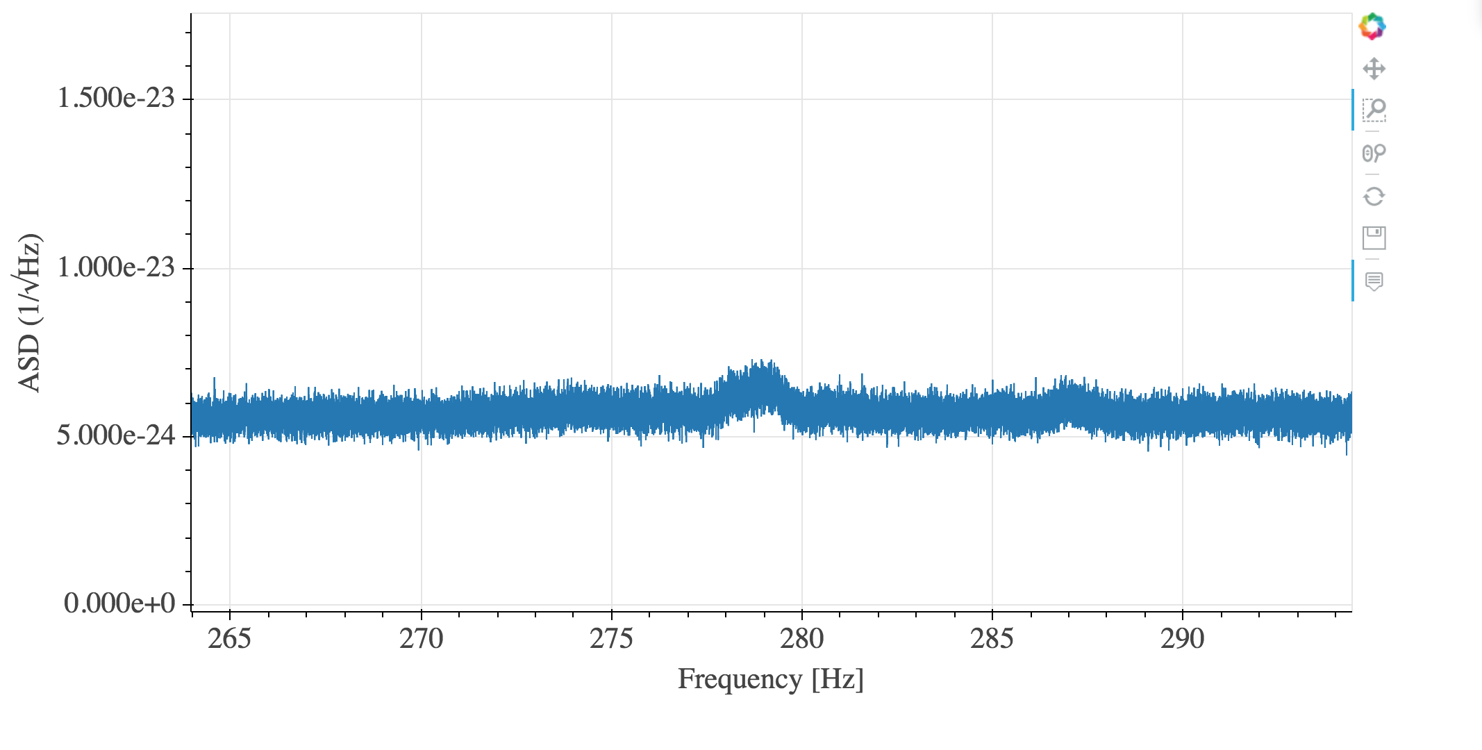
This looks pretty bad on 1800 s DARM averaged SFTs (see four figures attached). From a CW/Stochastic perspective these things are not lines, they are huge bumps in the spectrum.
As can be seen here: https://ldas-jobs.ligo-wa.caltech.edu/~keithr/O3spectra_DARM/#
the bumps in DARM at ~270 Hz started to be noticeable the 17th of April. The bumps at the other three frequencies (500, 800 and 1100 Hz) only are noticeable since 1 of May, so I guess that something changed that day which made the noise or the coupling way worse.
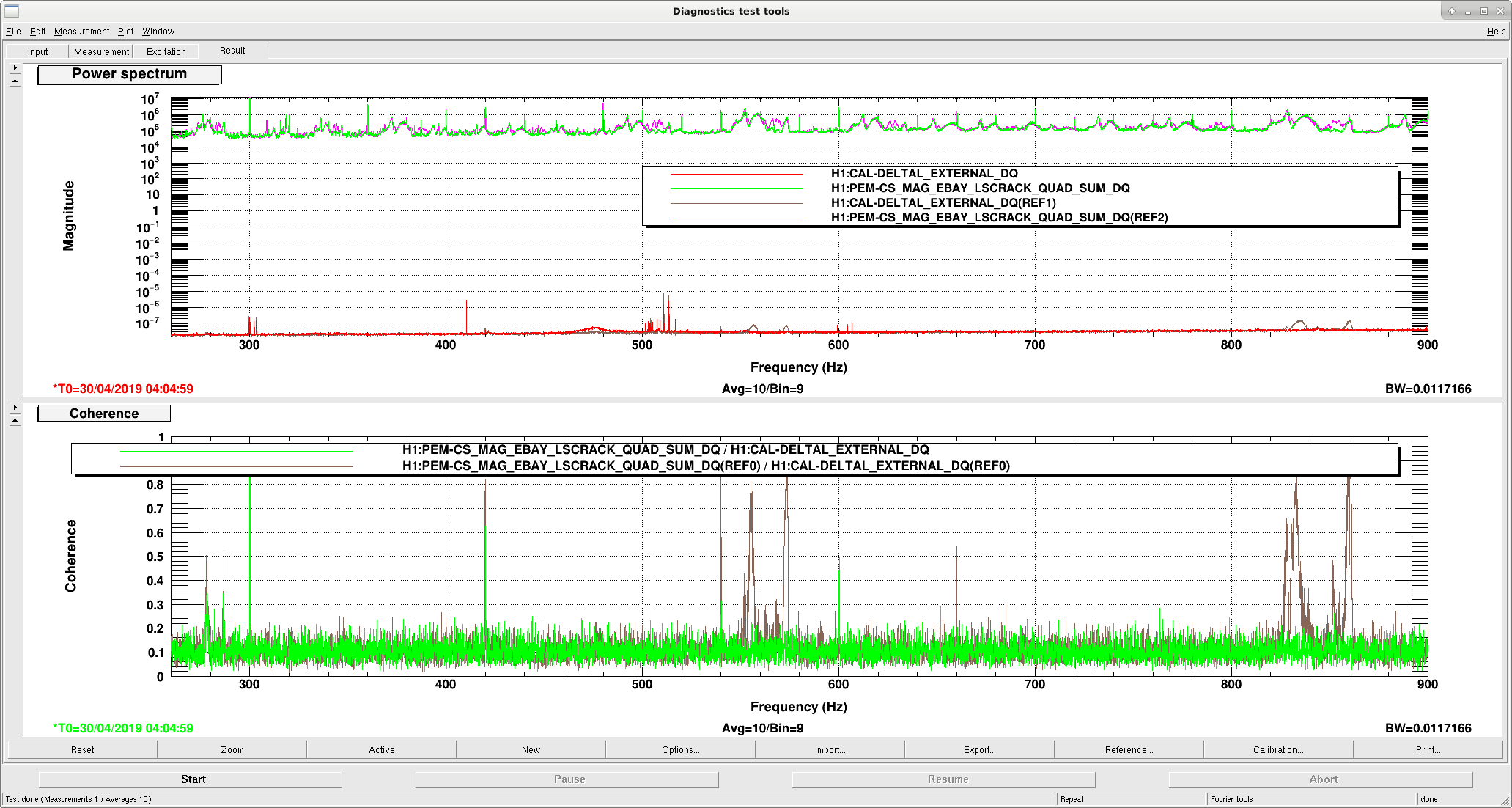
I checked the magnetometer channels in order to find coherence as was done here (https://alog.ligo-wa.caltech.edu/aLOG/index.php?callRep=47644). I found coherence only with some magnetometers in the corner station, mostly EBAY_LSCRACK, LVEA_OUTPUTOPTICS and LVEA_VERTEX, with INPUTOPTICS showing less coherence and SUSRACK no coherence at all at the frequencies where these bumps exist
The attached figure shows a comparison between the 30 April and today, showing how the coherence for LSCRACK MAG has increased
The coherence between PRCL and DARM is likely associated with ISI table suspension resonances (violin modes -like we damped in some HAMs). The GS13s are coherent with DARM at these frequencies (first page of the figure).
The excitation of the ISI tables does not appear to be driven from the ground, though, because the GS13s are coherent between distant chambers, like BS and HAM5, while the ground motion is not coherent at these frequencies (second page of the figure). Could there be a back-reaction from global control at these frequencies? Supporting this interpretation is the observation that there is a lot more coherence betweeen GS13s on the BS table and on HAM5 than with the GS13s on HAM6.
Pep Covas, Sheila Dwyer
Earlier today we added some notches to top mass damping and ASC loops to try to address some of the lines in DARM Pep writes about here: 48947 We went through a similar exercise in 2016, some links are included here: 31553
We found that the 40.9Hz HSTS resonances weren't notched in the ASC signals sent to PRM, PR2, SRM or SR2, so Pep added notches to all of those loops in M3 LOCK P and Y.
We also suspected that the 46.09 Hz line might be an HLTS resonance, in the resonance wiki they are predicted to be at 44.73Hz, but we weren't able to find measurements. Pep added notches for 46Hz to the top mass damping for both SR3 and PR3.
We also looked around a bit for something that could be done for the 27.7 Hz line, in the wiki the closest frequency is MC2 but it is not an perfect match. One thing that we can try is adding HSTS notches to the MCWFS loops, which are currently missing them.
It seems as though this has helped with the 46Hz line, and Pep is going to look more closely at the 40.9 Hz line with more data.
We lost the AS36 phasing that I did yesterday in full lock with the computer crash last night. I set the phase today during a DRMI-only time to zero the sum of the Q phase of AS_A_RF36, which gave me a phase 30 degrees different than my full lock phase yesterday.
We were able to acquire lock with this new phasing. As we thermalize, the Q sum is drifting away from zero. Right now at about 90 minutes into the lock the ideal phase (from atan(Q/I)) is 10 degrees different than the DRMI-only phase, in a direction consistent with yesterday's measurement. So, right now in full lock after 90 min, the ideal phasing is 20 degrees different than the value I found yesterday (and yesterday I might have overshot a few degrees).
So far, it seems as though Daniel is right that we could potentially servo the AS36 phase by calculating the arctan of Qsum/Isum. Probably we could do this in guardian, since it only needs a ~1 minute cadence or less; it's not a fast thing that would require a model change (although we could do that too or instead).
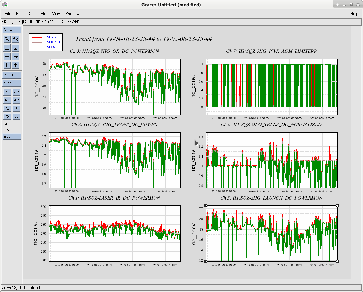
The multi-mode misery of the squeezer laser continues. 22 days ago the laser was adjusted and it looked reasonable for a few days with 45-50mW green output. Now it seems to vary between 35 and 45mW. At 40mW and below the power stabilization circuit is running out of range and rails the actuator.
It was reported that we cannot lock the squeezer laser when the noise eater is turned off. This is simply due to the fact that the auto-locker stops when there is an apparent error in the laser, and the current laser screen expects the noise eater to be on. Added a new nominal state for the noise eater relay that should take care of this problem in the future. It requires the new Beckhoff code to be activated first.
I took the "opportunity" of a lock loss due add the noise eater relay nominal setting to the SQZ laser. Now the TTFSS servo will work when with the noise eater off all the time.
SQZ laser multi-mode issues now associated with FRS ticket 12883.
Ops Shift Transition: 05/08/2019, Eve Shift 23:00 – 7:00 (16:00-00:00) - UTC (PT)
State of H1: Locked
Intent Bit: Commissioning
Weather: ~10 mph wind, sunny
Primary 0.03 – 0.1Hz: 0.01 um/s
Secondary 0.1 – 0.3Hz: 0.1 um/s
Outgoing Operator: Jeff
Quick Summary: Locked for ten minutes, Jeff is in charge of the IFO for calibration work.
It looks like the PR3 sliders weren't restored after the Dolphin crash last night, so our IFO alignment has been a bit wonky all morning (one lock we saw some beam on AS AIR even with the beam diverter closed, which indicates something is definitely funky).
I restored the PR3 sliders, and now JeffB is doing an initial alignment starting with INPUT_ALIGN (the green arm alignment should still be fine from Corey's alignment last night). Hopefully this will help things out a bit.
Oh wow! And the PRC_ALIGN section of the INITIAL_ALIGNMENT I ran, ran completely on its own, so I didn't worry about it so I could focus on the other problems (hence, I didn't mention PRC ALIGN in my Alog....it and the Green Arms did not give me issues when I tried them).
Sorry about that! With SUS, I only looked at sliders for mirrors which were giving me grief, and since PRC was taken care of by Guardian I didn't even look at them.
Good Luck!!!
P.S. Not sure of best check for SUS after dolphin crash. Sounds like we should go through and restore ALL of them to a good time (instead of do them willy nilly like I did). What's the best way to do this?
I caught this by looking at a time machine of IFO_ALIGN_COMPACT for 24 hours ago. So, I usually look at all of the slider values. Ndscope is also fine, but I find this to be quicker.
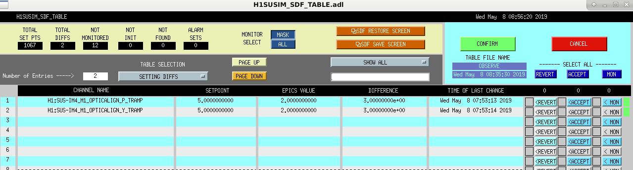
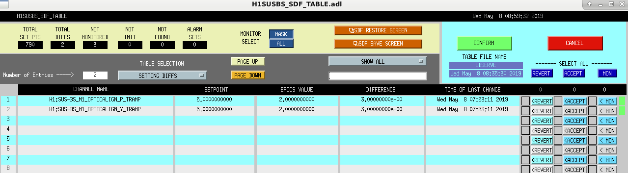
Also, I have re-monitored all of the slider values for the optics in the safe.snap files that are loaded when the models reboot. We don't accept values in the safes all that often, but we do sometimes. For example, I cleared all of the safe.snaps a week or so ago, but didn't think to look at the not-monitored channels. By re-monitoring them, we'll hopefully get a more recent value for all of the sliders when we have an unexpected reboot.
A consequence of this is that, for the suspensions whose observe.snaps are just links to their safe.snaps, we will have to accept any OPTICALIGN SDF diffs when we go to Observing. However, the suspensions that have this situation are ones like IMs 1-3, the RMs and the OMs that really shouldn't be changing ever. So, operators in general shouldn't see these as diffs every lock. If you do see these as diffs when you are trying to get to Observe, let's continue to screenshot them so that we can understand why they are changing.
Several other suspensions also have the safe.snap linked to the OBSERVE.snap, so each time we run inital alingment now we are having to accept sliders for many optics. I think it makes sense to un-monitor these, and find a different way to keep track of the slider values.
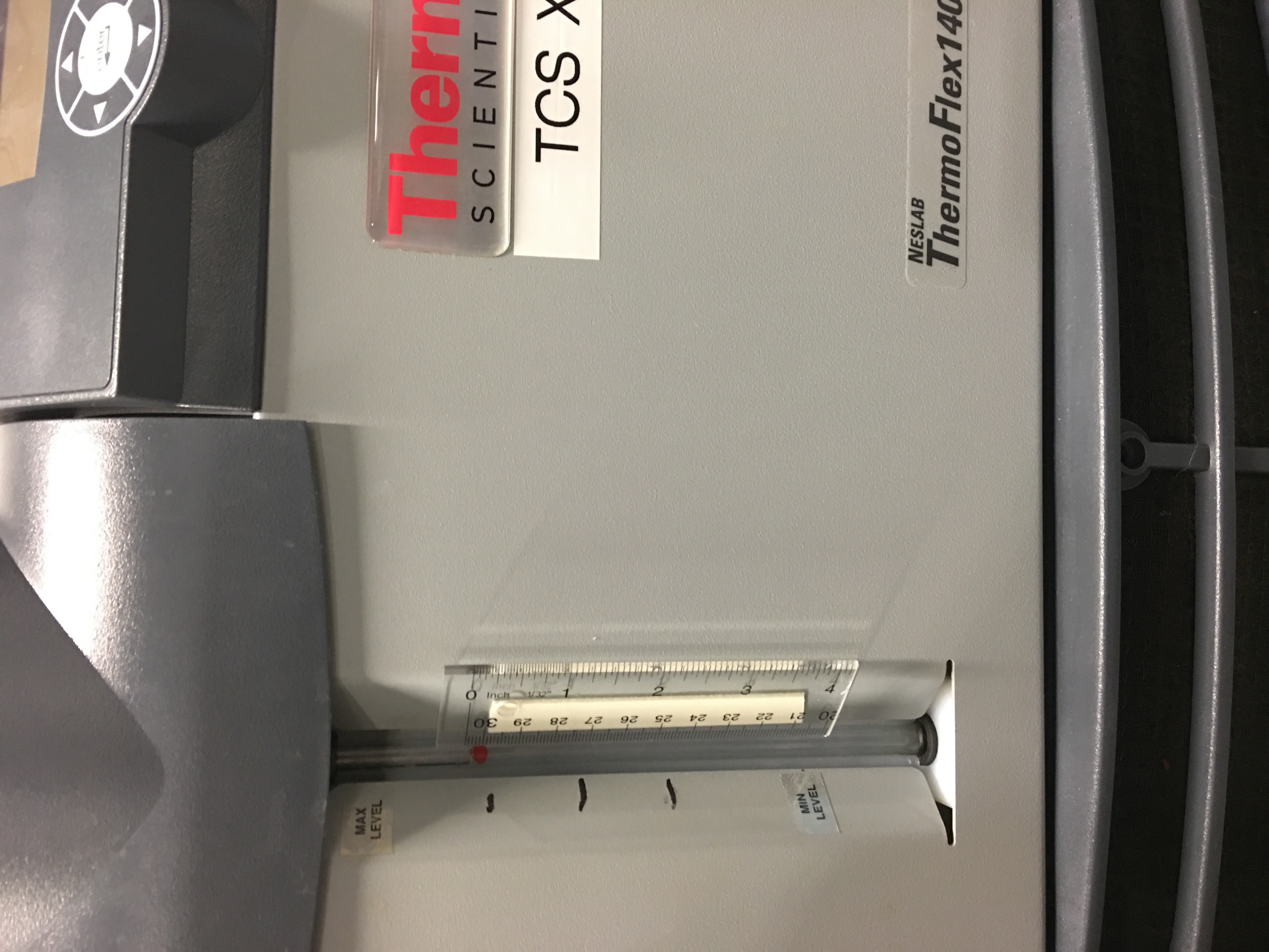
Added 100ml water to the Crystal Chiller. The Diode Chiller water level is good; no water added. Both filters look good. Closing FAMIS #10508
no water required at this time.
After relocking had code error for GRD-HIGH_FREQ_LINES_MAIN node. Pep made a code change and will reload at the next opportunity.
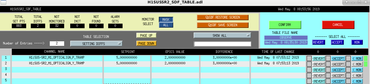
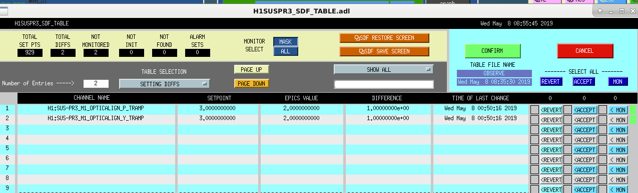
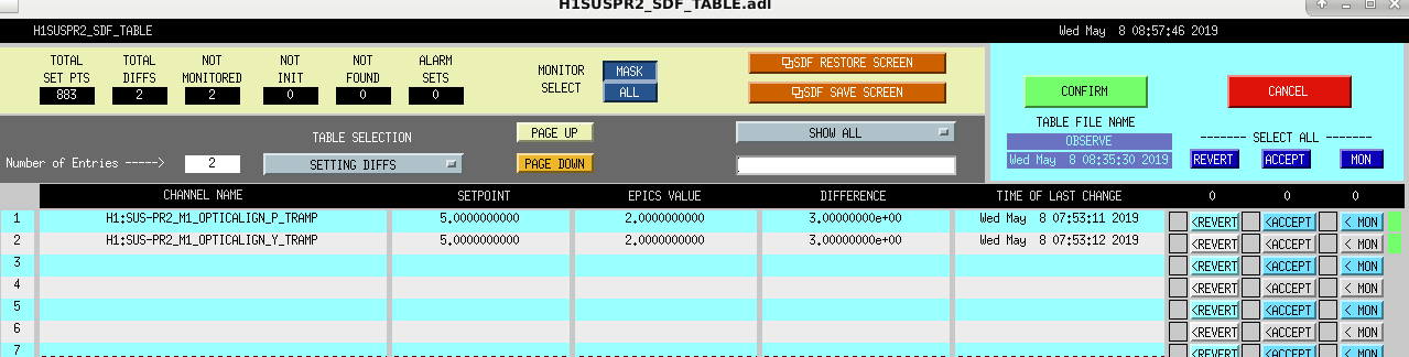
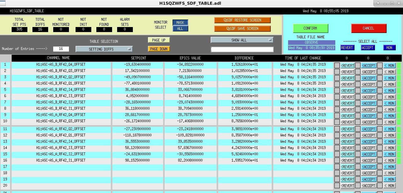
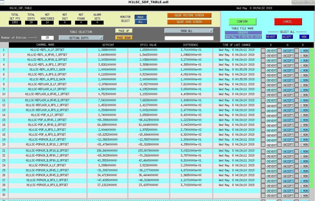
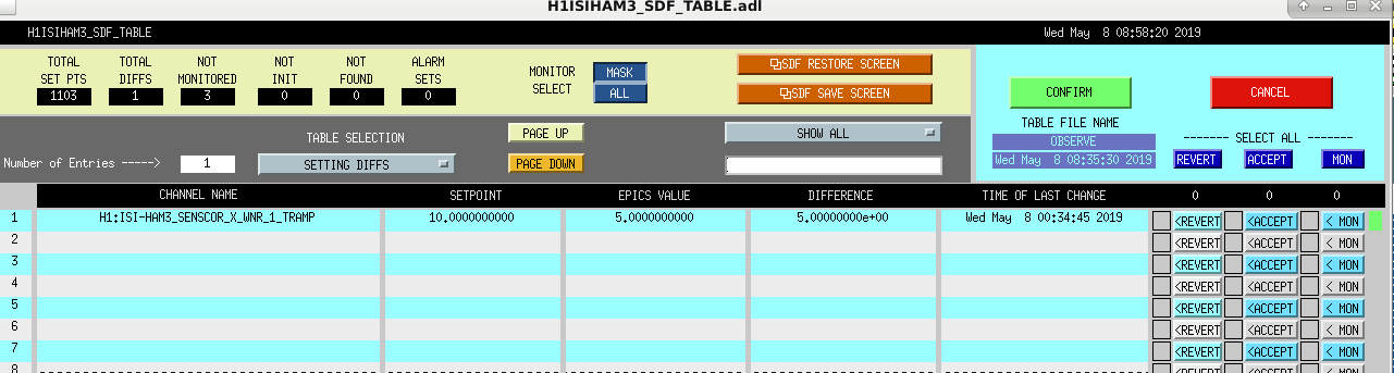
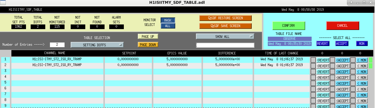
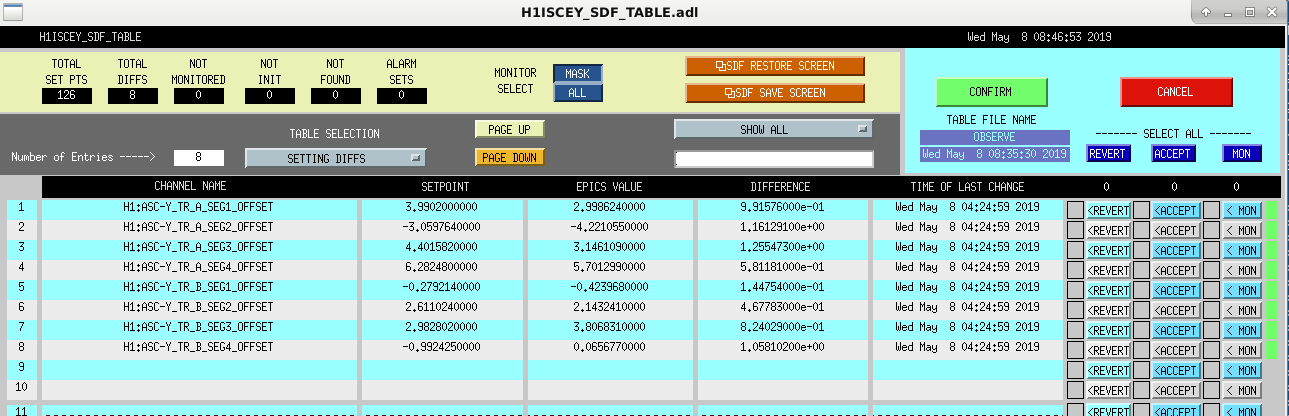
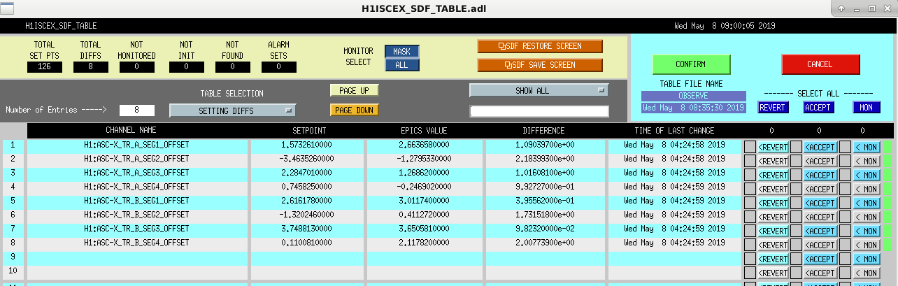
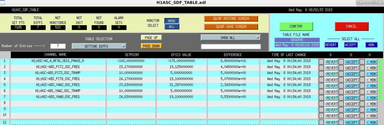
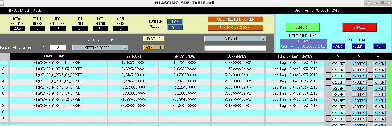
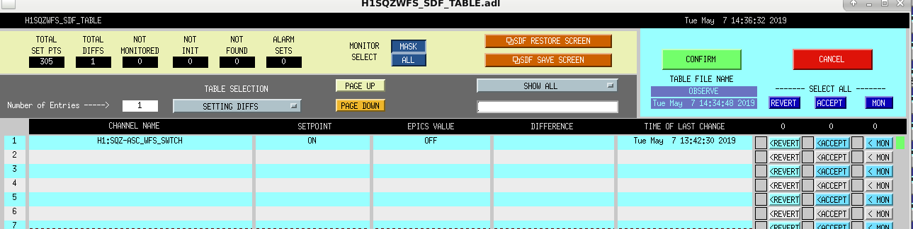
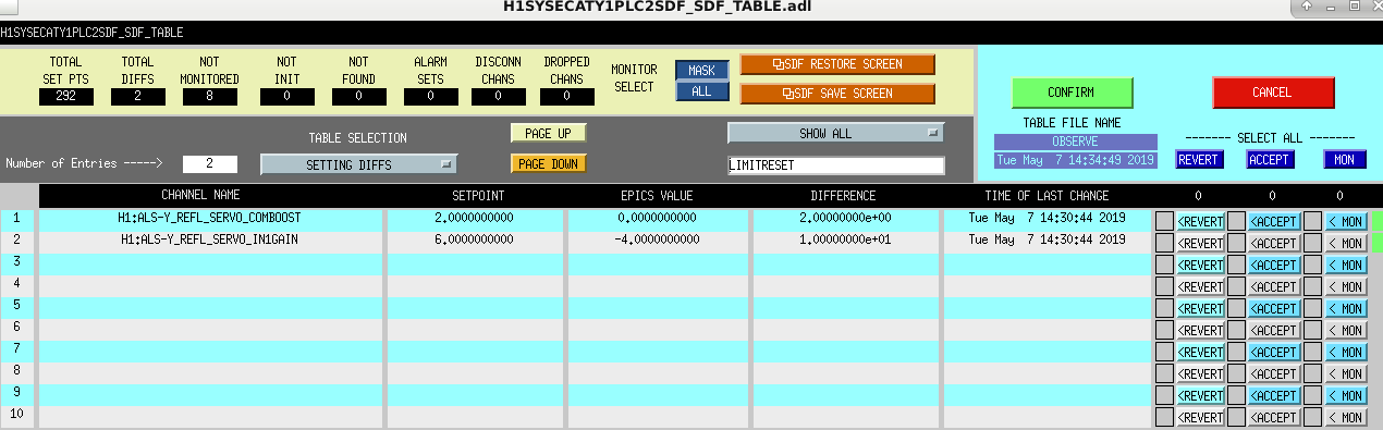
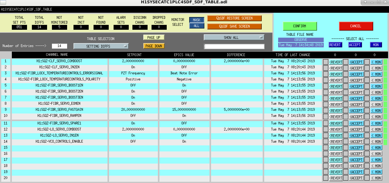
Relocked the IFO (Thanks to Ed & Corey) at NLN and went back into Observing after accepting the SDF Diff in the attached screen shots.
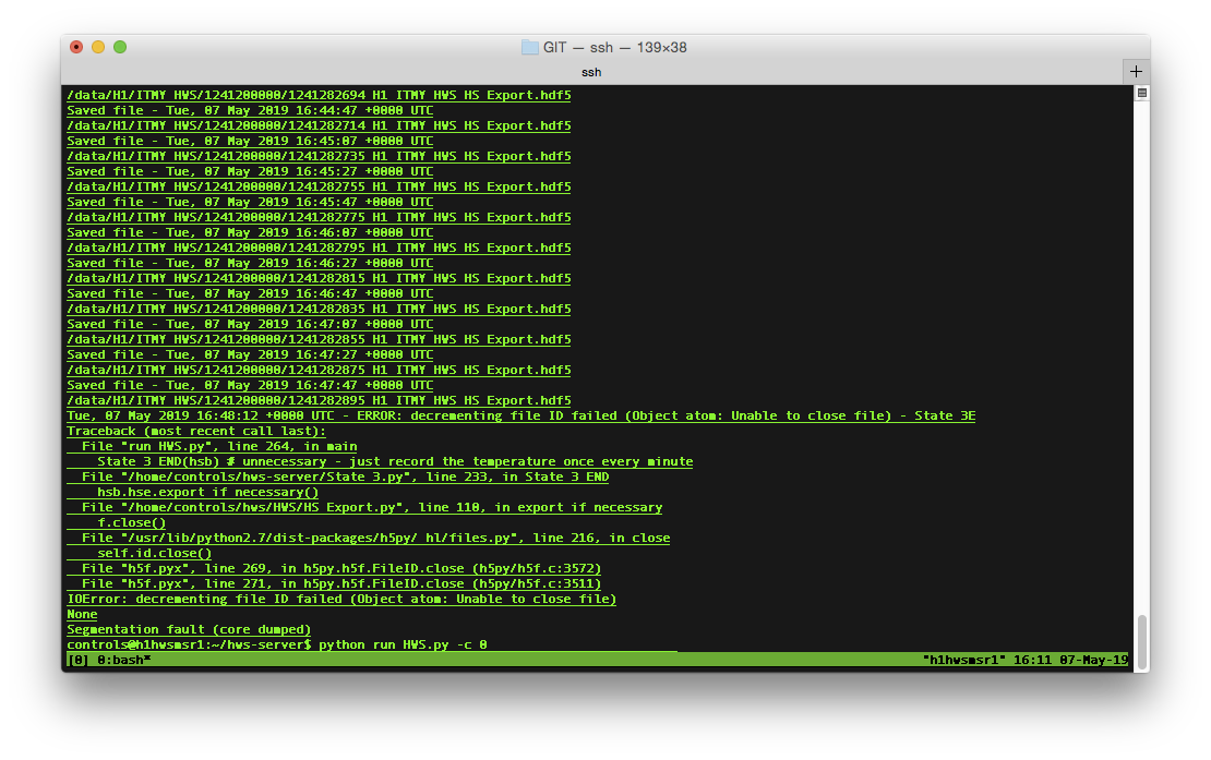
I received a call from Jeff Bartlett that the 3 working HWS have all stopped (ITMX was not running due to the clipping issue in the vertex).
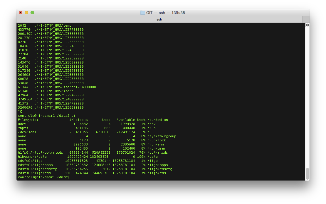
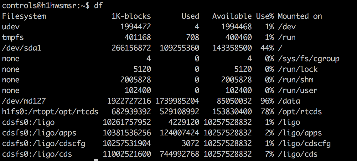
After getting permission from Jeff, I logged into the HWS machines and found that they all stopped at the same time. Checking the disk usage confirmed my suspicion that the data disk (/data) was indeed full. We'll have to look into whether the clean-up script is still working - it might be but it's possible that it wasn't clearing out everything and this, like Thanos, was just inevitable. Once I confirm that all data more than 48 hours old is archived at CIT, we can remove all the old data and get the HWS code running again.

I've removed the hdf5 files from the 1235600000 - 1236500000 directories in ITMX & ITMY to bring the disk usage down to 96%. These files were backed up to LDAS so they are not lost. We should think about a long term solution to automatically remove files.
I started all four cameras back up and they appear to be taking data again.
Keita made the point that we should phase AS36 where it needs to be for putting the BS signal all in one quadrant, and then use the MICH ASC offset if we need to adjust the BS pointing at 35W. Keita, looking at the BS resonances while we're in lock, guesses that we're using a phase about 70 degrees away from what we should be.
When we had ~just gotten to 35W IFO lock I put in a BS pitch dither line at 8 Hz with 600 counts, and phased AS36 to minimize the peak in AS_A_RF36_I_PIT. So far, the ASC seems okay, although we're only about an hour into the lock. This doesn't put the SUM of Q to zero, which leaves us vulnerable to DC centering-like effects.
As Daniel has already noticed, to do this I have moved the AS_A_RF36 phase 34 degrees opposite of what I had been asking operators to do, which puts us 74 degrees different from what we had been using for the later parts of lock (after about 90 mins). This is nearly exactly what Keita had guessed by roughly eyeballing some spectra. The next question becomes: how was it working at all?? Have we basically not been controlling our BS motion for the last few days? I'm hopeful, although haven't confirmed, that we'll be able to acquire lock with this phase and not have to change things part way through the lock, with the idea that we had been acquiring with a phase about 40 degrees wrong, but then moving it a further 30 degrees in the wrong direction made the gain in MICH ASC so low that we weren't controlling the BS, which is why we struggled to lock.
Another way to phase the RF36 is to put the entire sum signal into the in-phase. This way the quad-phase, which is used for MICH angular control, is insensitive to centering.
After the GRB stand down was over I did this; I moved the AS_A_RF36 phases by another -28 degrees to zero the Q SUM. This made the yaw ASC oscillations significantly smaller, although I'm not sure that they're completely gone.
This is now 60 degrees different from the 2W value that we'd been using, and 101 degrees different from the NomLowNoise value that we'd been using. Gah, so confusing how the ASC was even working.
If the IFO is fussy on relock, you can still run the 'revert' command from alog 48948:
z write H1:ASC-AS_A_RF36_SEG1_PHASE_R -175 H1:ASC-AS_A_RF36_SEG2_PHASE_R -190 H1:ASC-AS_A_RF36_SEG3_PHASE_R -170 H1:ASC-AS_A_RF36_SEG4_PHASE_R -175
But, I'm hopeful that we'll be able to relock with this new phasing. We'll see....
The ASC Yaw signal is oscillating after the IFO has been up for the last few hours. Spoke with Jenne, and said to run the following command: z step H1:ASC-AS_A_RF36_SEG1_PHASE_R -1,28 H1:ASC-AS_A_RF36_SEG2_PHASE_R -1,28 H1:ASC-AS_A_RF36_SEG3_PHASE_R -1,28 H1:ASC-AS_A_RF36_SEG4_PHASE_R -1,28 -s 1
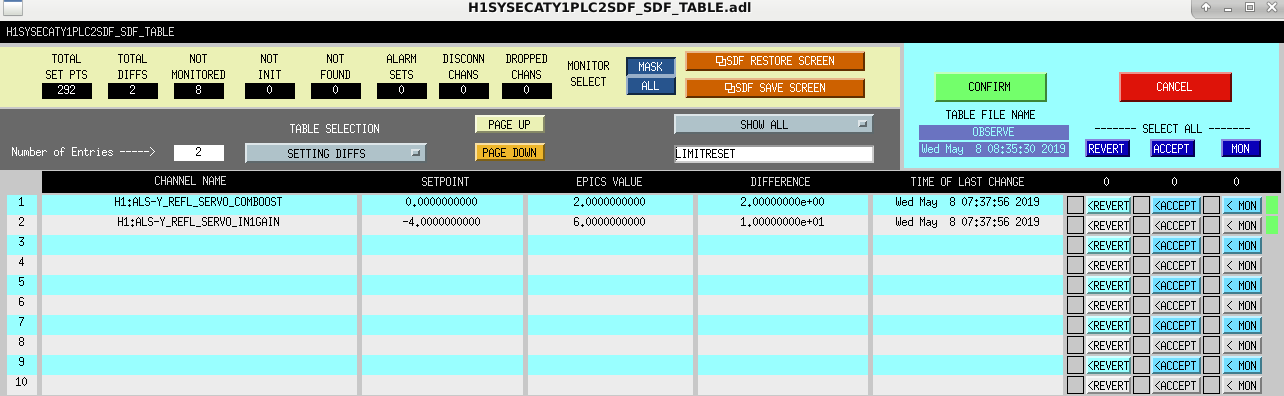
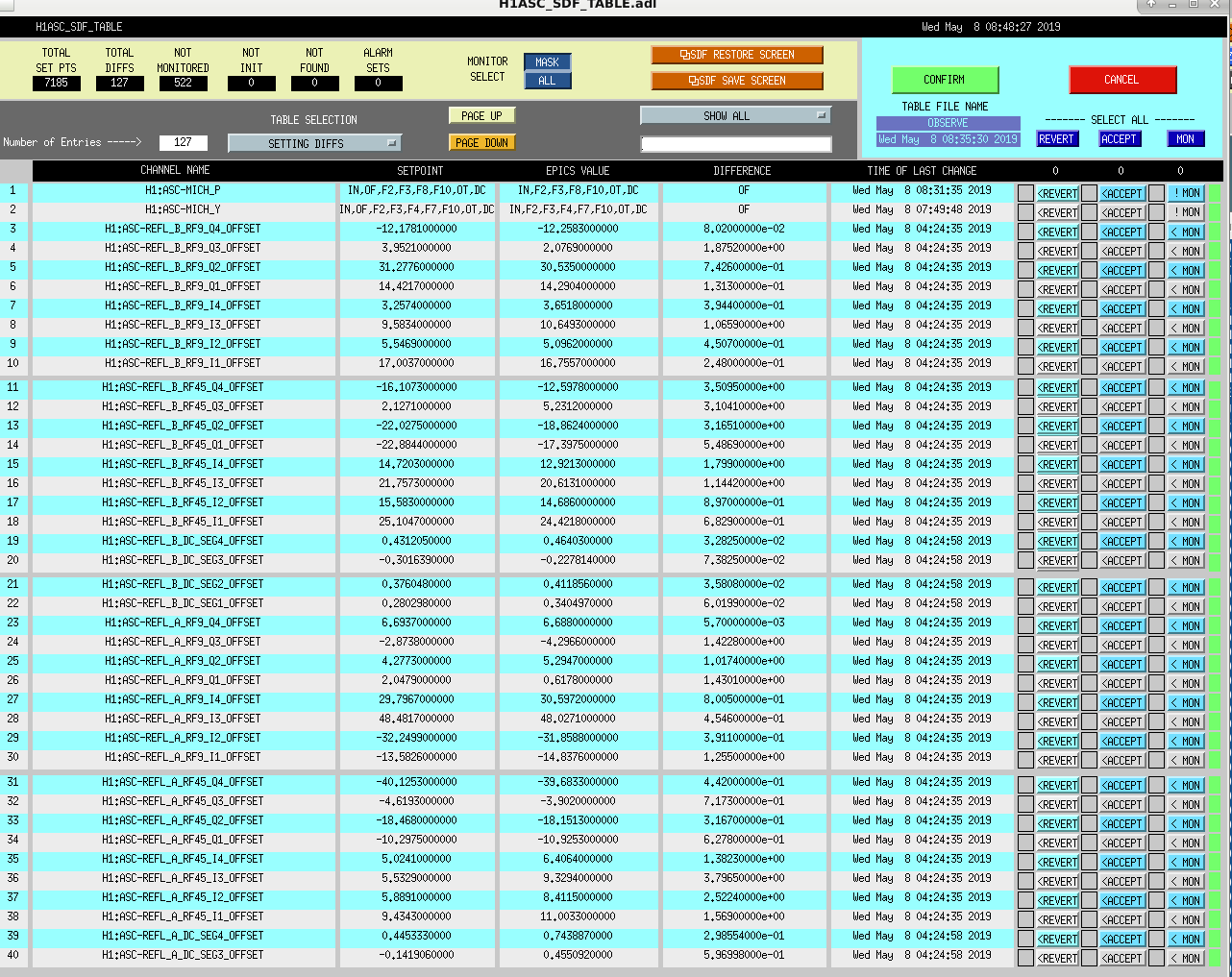
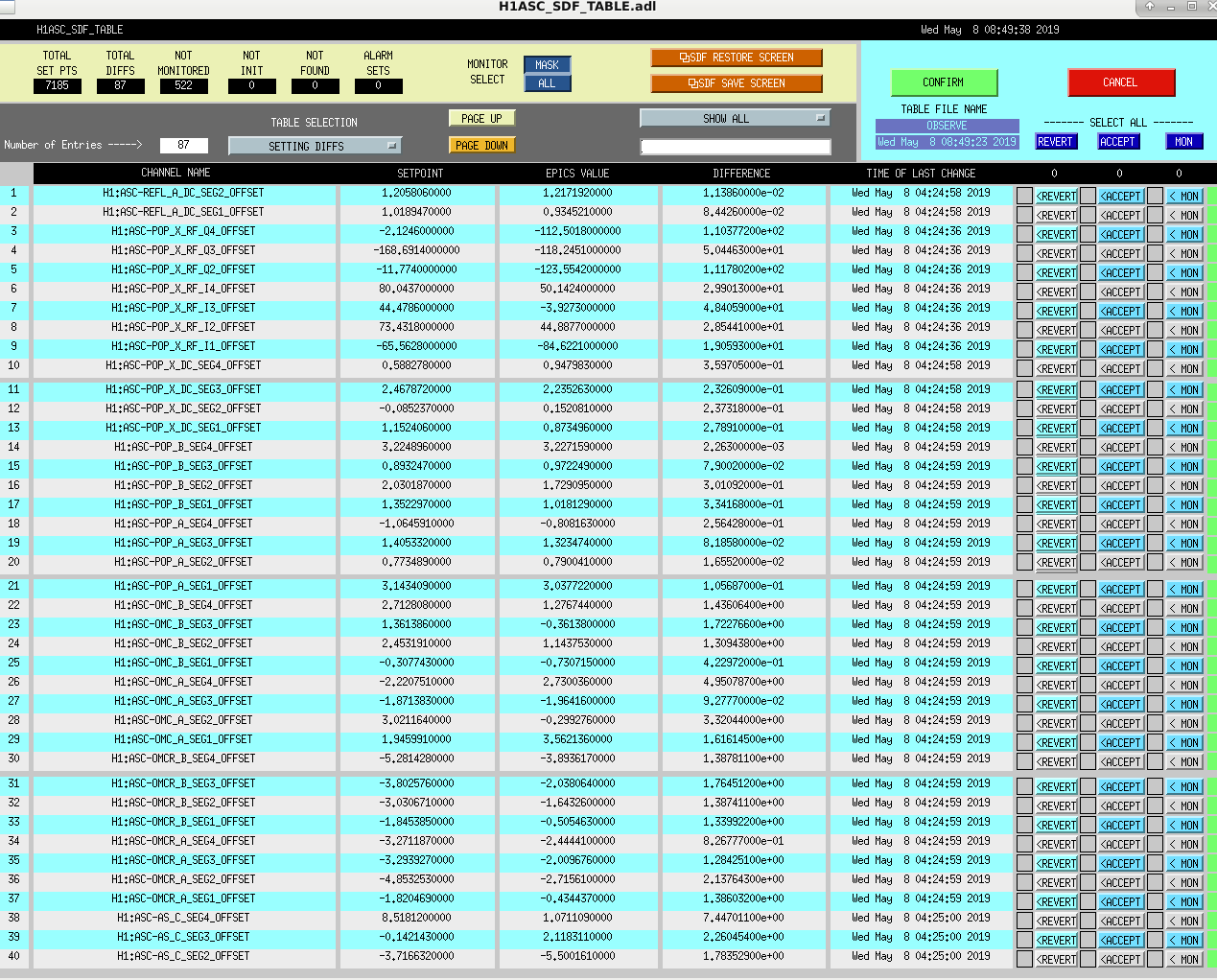
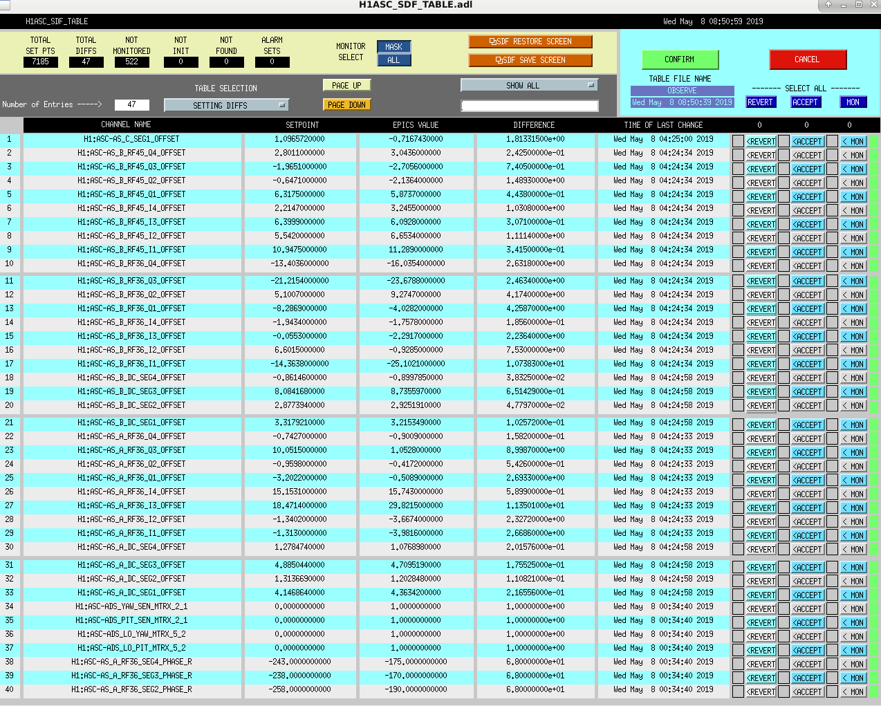
Ran initial alignment and relocked the IFO after the Tuesday maintenance window. Ready to go into Observing after accepting the SDF Diffs in the screen shots posted below.
These squeezer SDFs were fixed and reverted. The squeezer guardian (SQZ_MANAGER) was stuck, and so we weren't injecting squeezing. Even with the SDFs accidentally accepted, the guardian properly prevented us from going to Observing, since the SQZ_MANAGER was not in its nominal state. It turns out that even though JeffB had toggled the squeezer's noise eater on, then off, that wasn't enough to convince the squeezer to lock all the way to injecting squeezing (we tried turning it back off only a few seconds, so that we didn't forget later).
So, I have added to the SQZ_MANAGER guardian to turn ON the squeezer noise eater in the DOWN state, and to turn back OFF the noise eater in the SQZ_ASC state (just before it's nominal state).
I have not yet loaded the SQZ_MANAGER guardian - this should be done next time we are out of Observing for a moment, so that operators no longer should have to deal with this. I am leaving a sticky note with JeffB and his backup Cheryl as a reminder.
I moved the sqz noise eater ON to the Locking_TTFSS state, since it seems like we jump from Squeezing straight to Locking_TTFSS, and don't go through DOWN, so it hasn't been getting turned on.
Cheryl Daniel
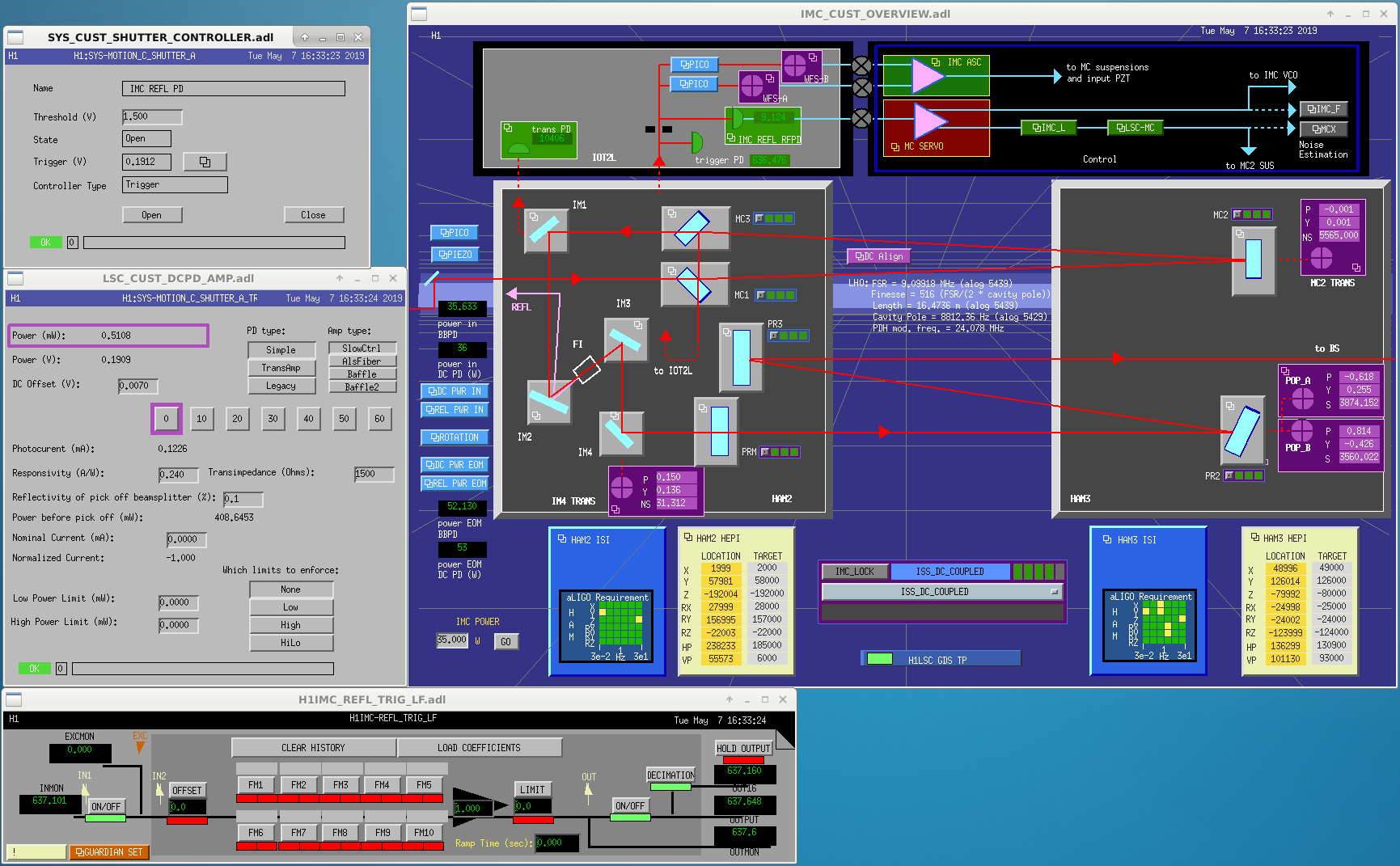
The IOT2L table drawing can be found here: D1300357. We installed a 2" turning mirror after IO_MCR_M3 a the location of IO_MCR_BD2. The beam is sent to the right on the drawing where it encounters a 2" lens with focal lens 100mm. A Thorlabs PDA100A2 was installed somewhat prior to the focus of the beam and acts the trigger PD. Its gain was set to 0dB. A 14mm reflective shutter with was put in front of the IMC LSC PD. When closed the reflected beam is steered onto a razor blade beam dump.
Next we swapped IO_MCR_BS1 with a 90:10 beamsplitter and increased the power using the halfwave plate IO_MCR_HWP1.
The power on the photodetectors before and after:
| in lock |
Before |
Before 35W |
After 1.85W |
After 35W |
|---|---|---|---|---|
| IMC REFL DC | 0.08mW | 1.4mW | 0.54mW | 9.15mW |
| WFS_A DC | 0.037mW | 0.65mW | 0.028mW | 0.46mW |
| WFS_B DC | 0.029mW | 0.51mW | 0.022mW | 0.36mW |
The wavefront sensors seem to have lost about 30% of power, whereas the DC PD power has increased by about 7.
We reduced the IMC IN1GAIN by 20dB. This gives us a ugf around 42kHz. Later in the locking process this gain will be increased by another 3dB which would give us a ugf around ~65kHz. This is a little bit puzzling, since we would expect a 16dB gain to give us the old ugf, which was around 70kHz.
The -20dB was put in the IMC_LOCK DOWN state (for IMC acquisition) as well as lscparams.IMC_IN1_gain. This should be all of the places that the gain is hard-coded. Everywhere else is relative (eg. CARM_TO_ANALOG has a +=3 to add 3dB to whatever is the current value).
I forgot to save a screenshot of the IMC OLG measurement when we had IMC-only (no IFO lock), but that had a UGF of about 41 kHz. (I have the data, but will have to remind myself how to call the plotting scripts...)
Attached is a screenshot of the IMC OLG while the full IFO was locked at Engage_ASC_for_full_IFO, so 2W lock, CARM on its final sensor, DARM still on RF. Looks like ~58kHz after the +3dB from CARM_to_analog.
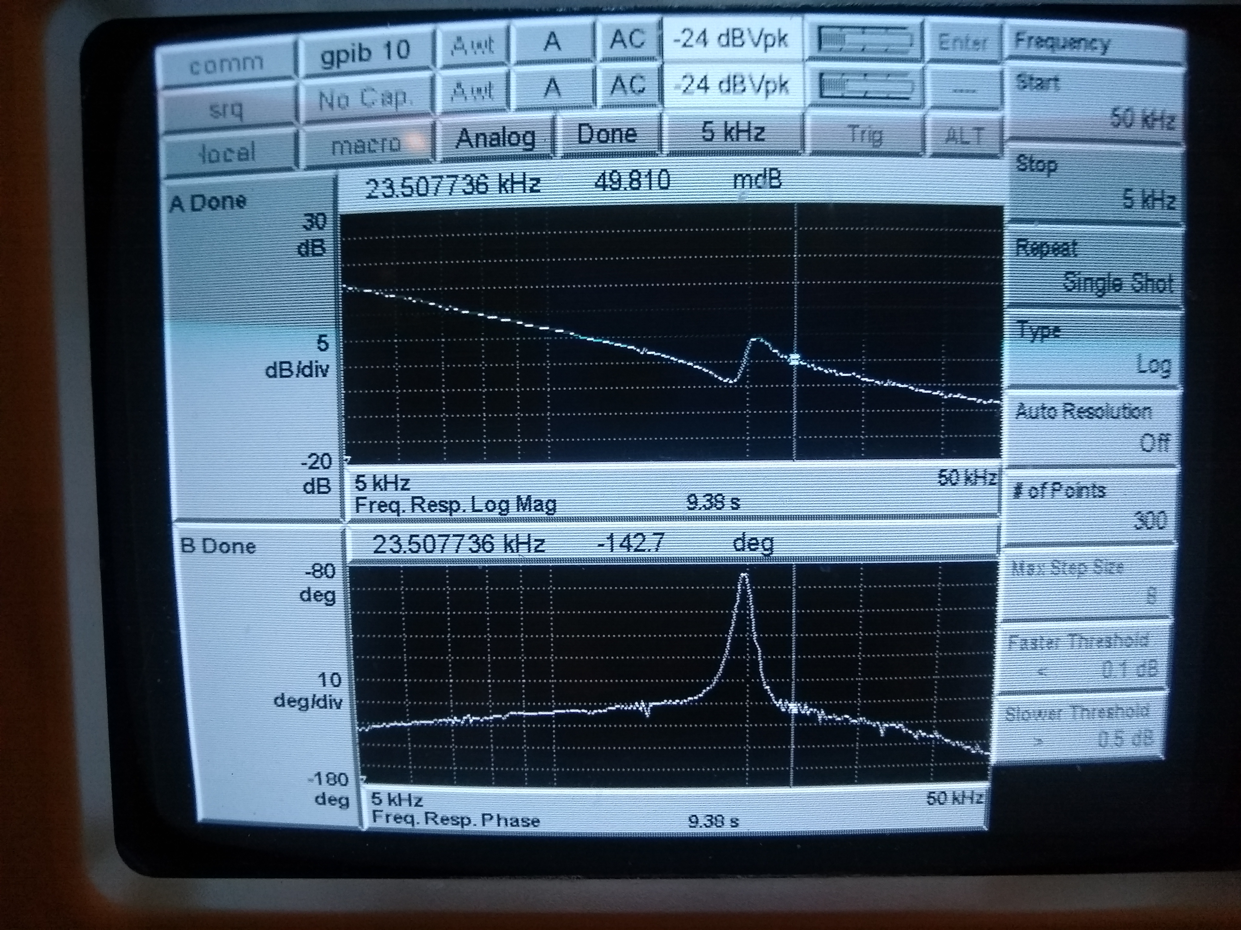
Attached are the IMC and CM transfer functions when fully locked at 35W. The IMC ugf is around 72kHz (excellent phase margin!), whereas the CM ugf is around 20kHz.
This seems to confirm that the optical gain has changed by a factor of 10, whereas the power increase when locked is only around 7. One way to resolve this is with a small amount of light in the wrong polarization incident to the IMC. Due to the halfwave plate most of it would be directed onto the photodetectors, whereas the correct polarization would be attenuated. This would mean the shot noise limited sensitivity has gotten better by approximately 3.8, rather than 2.6 which we would have expected form a factor of 7 increase in power.
Here is a snap shot of the updated medm screens.
Remeasured the error and control spectra of the IMC REFL servo and the LSC REFL servo signals. The IMC signals are mostly the same. The CM servo shows significant improvements at frequencies above ~30Hz. The improvement at 1kHz is a factor of ~5.7, when compare with a lock just 13 hours ago. Since we were only detecting 1.4mW of light previously, the dark noise was probably at a similar level as the shot noise.
Koji and I measured the shot and dark noise levels for the REFL and IMC PDs alog 46552. According to the IMC REFL plot, we were previously limited by dark noise with 1.4 mW on the PD. Now we are squarely in the shot noise limited regime.
We took about 4 hours of time for commissioning today:
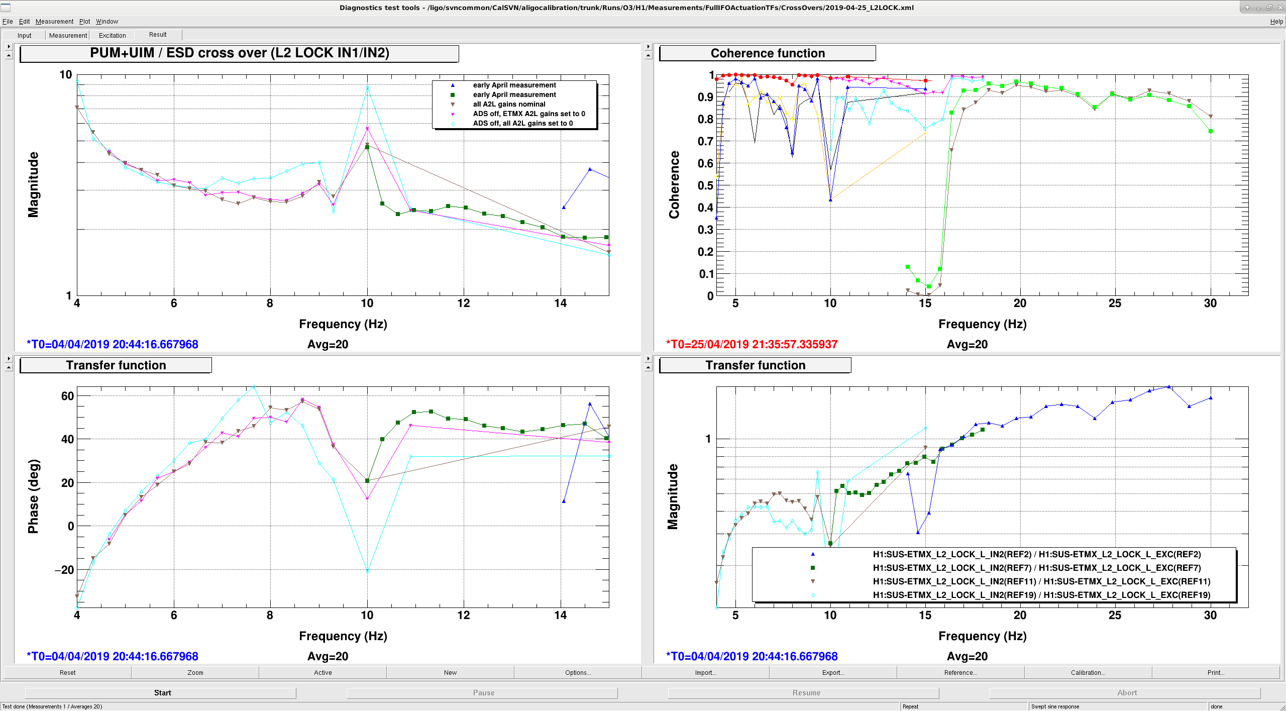
A quick summary of the cross over measurements (Jenne, Sheila):
Motivation:
Measurement:
Here are the measurements from this time plotted against a pyDARM model.
The blue line is a model of what the L2 LOCK IN1/IN2 measurement is expected to look like based on the pyDARM model of the actuators. The green dots are measurements of this crossover made on April 3rd, they are plotted here just so that you can see some higher frequency data (we didn't retake any higher frequency measurements)
These measurements could be explained by a coupling of the length drive to either the angle of the optic through a mechanical coupling or to the angular sensor, the ASC loop then tries to actuate in response, but there is a coupling from angle back to length because we are not doing a nice job of a frequency dependent angle to length decoupling. When we turned off the A2L decoupling, by setting the scalar gains to 0 but not running the ADS so that the spot positions stayed in their normal positions. In principle, a more accurate frequency dependent A2L decoupling could be used to reduce this effect.
In 47824 and 47982 we saw that when we turned off the L2A decoupling filters, which increased the gain of the PUM by getting rid of the L2A2L coupling that comes from having our spots well off center and not routing the L2A output through the A2L decoupling, we had a crossover instability around 8 Hz. This was solved by turning off the 4.5Hz boost in the PUM lock filter, which doesn't make complete sense but it is plausible given these emasurements that the problem with the boost was caused by these angular cross couplings, especially if there are features that are not resolved in this measurement.