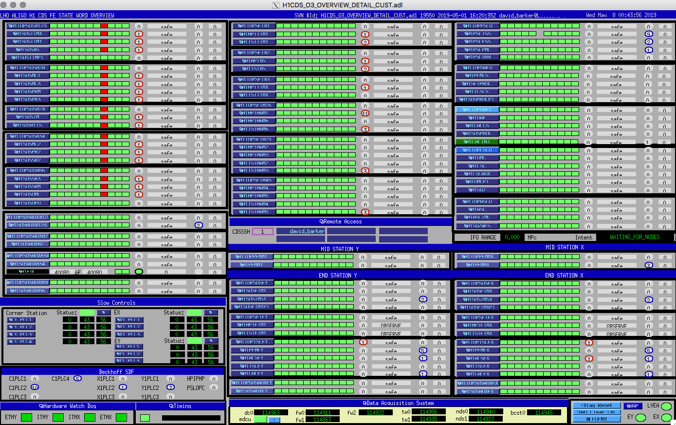
Looks like all front ends on the corner station dolphin network are having issues, I'm starting the recovery.
I've captured dmesg and dolphin logs for later analysis, I'm now restarting all the models in the order SUS, SEI, ISC.
All models restarted with no issues.
The CW psinject had stopped because h1calinj was restarted, and it sucessfully restarted itself now that it is under systemd control.
I cleared all the IPC errors and DAQ-CRC counters. Attached CDS Overview shows that the only red is due to the suspension models still have watchdogs enabled.
I'm handing the system over to Corey for IFO recovery.
TITLE: 05/07 Eve Shift 23:00 – 07:00 (16:00-00:00), all times posted in UTC
STATE of H1: Down
INCOMING OPERATOR: Corey
SHIFT SUMMARY: Was locked when I arrived, had an uneventful shift with two GRB’s. A few minutes after Corey arrived, there was some system-wide computer failure and we lost lock (Corey will post more details).
LOG:
23:00 (16:00) Start of shift
23:17 (16:17) GRB (E331702)
23:31 (16:31) Cheryl to VPW -- pick up equipment
00:18 (17:18) Out of Observing for an ASC change
00:26 (17:26) Back into Observing
03:00 (20:00) GRB (E331712)
07:00 (00:00) End of shift
07:04 (00:04) Computer crash
Pep, Lilli,
Pep has taken 4 sets of HF measurements. The data are in ^trunk/Runs/O3/H1/Measurements/FullIFOSensingTFs/ (HF0, HF1, HF2, HF3).
Adding those HF measurements into the multi-meas GPR fitting, the results are shown in the first two pdf files. (Script: ^trunk/Runs/O3/H1/Scripts/Uncertainty/process_allmeas_writeGPRHDF5_20190502_addHighFreq.py)
Note that this fitting also includes the 0502 high-freq sweep (coherence is worse). By removing the 0502 sweep, the GPR fitting results are in the third pdf. The difference can hardly be told by eye. Including the poor high-freq sweep slightly improves the fitting.
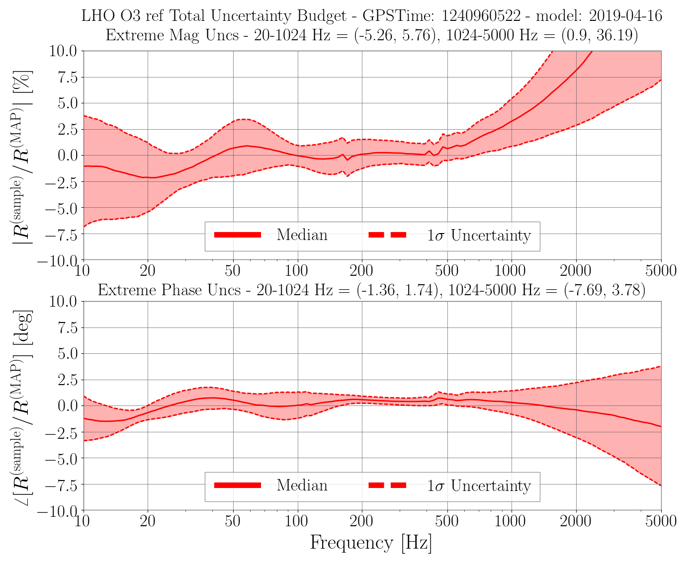
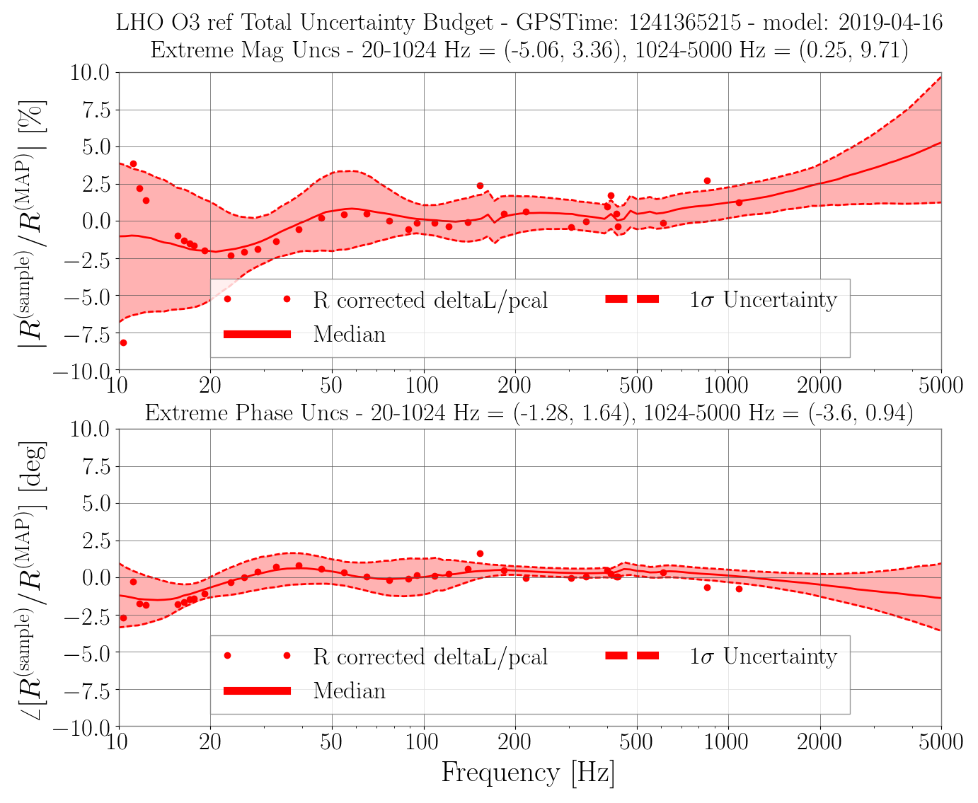
The updated uncertainty estimate is shown in the first png (cf. the previous results in the 2nd png). The high-freq systematic error improves a lot.
Today I found the pressure relief line of the EndY HEPI full of fluid (a couple feet of 1/2" or something hose.) This is usually an indication to me that the pump station experienced a high pressure event on the output. Attached is a snap of the output pressure and the control signal around 8 March--if this is the time this over pressure occurred it is a pretty good indication of how observant I really am given that I've been there 6 or 8 times since then!
Anyway, the plot shows that several attempts were made at restarting/repowering things after the fuse blow noted in 47392. The data shows the output of the controller at max, 2048 while things were reengaged and spiking the pressure and opening the pressure valve letting fluid escape. The last one, I'm not sure why it was different but was at max reading, ~104 psi for 10 to 20 seconds. This is likely the event that filled the relief line with fluid. Looks like time for training on restart and obviously I should have inspected the system area more thoroughly after this event!
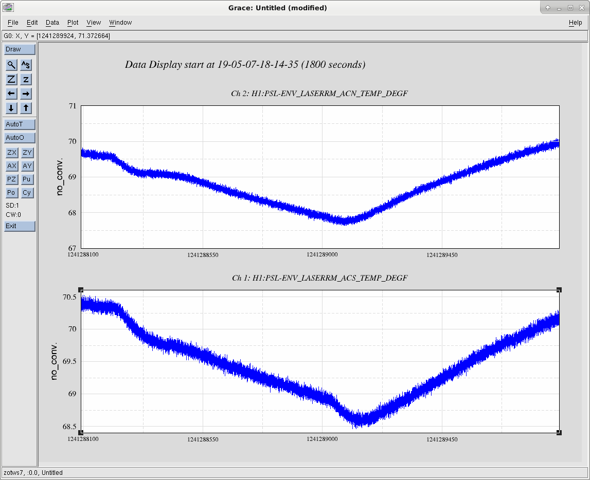
Jason and I cleared out of the PSL around 11:15AM PT, and used a multi-stage transition to Science Mode, which means that the temperature in the PSL recovered within a few tenths of a degree, within about 30 minutes, allowing for locking as soon as Maintenance was over (or possibly a bit early).
Timeline of changes:
- Jason, Cheryl
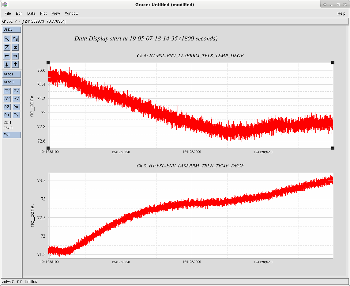
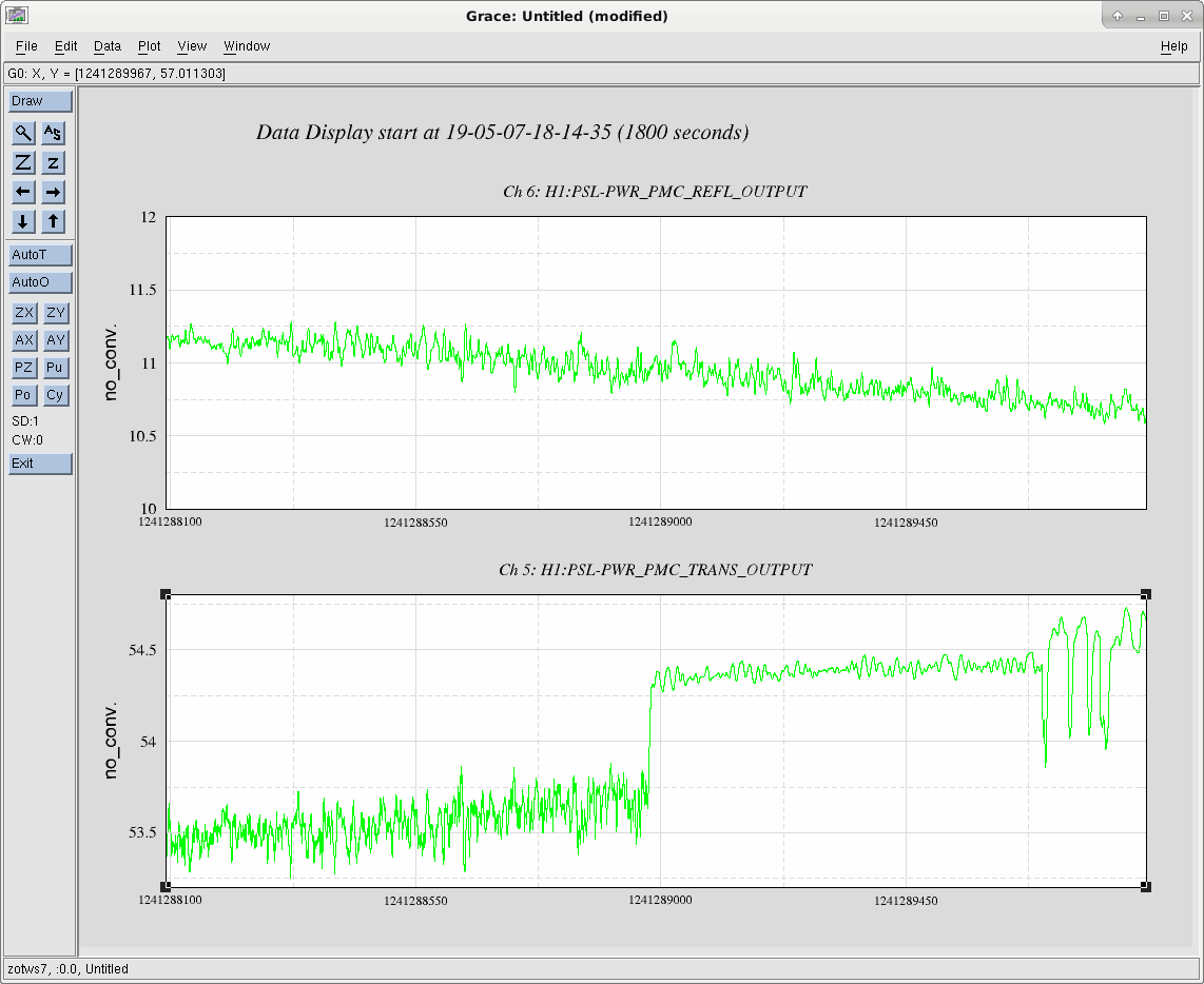
Three Plots, 18:16 UTC + 5 hours:
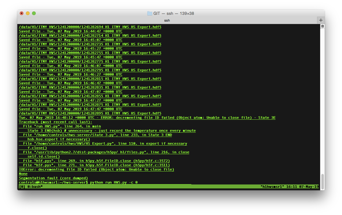
I received a call from Jeff Bartlett that the 3 working HWS have all stopped (ITMX was not running due to the clipping issue in the vertex).
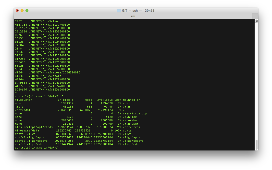
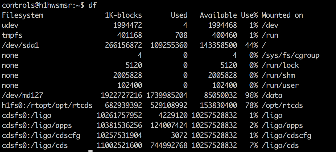
After getting permission from Jeff, I logged into the HWS machines and found that they all stopped at the same time. Checking the disk usage confirmed my suspicion that the data disk (/data) was indeed full. We'll have to look into whether the clean-up script is still working - it might be but it's possible that it wasn't clearing out everything and this, like Thanos, was just inevitable. Once I confirm that all data more than 48 hours old is archived at CIT, we can remove all the old data and get the HWS code running again.

I've removed the hdf5 files from the 1235600000 - 1236500000 directories in ITMX & ITMY to bring the disk usage down to 96%. These files were backed up to LDAS so they are not lost. We should think about a long term solution to automatically remove files.
I started all four cameras back up and they appear to be taking data again.
Ops Shift Transition: 05/07/2019, Eve Shift 23:00 – 7:00 (16:00-00:00) - UTC (PT)
State of H1: Locked
Intent Bit: Observing
Weather: ~15 mph wind, sunny
Primary 0.03 – 0.1Hz: 0.01 um/s
Secondary 0.1 – 0.3Hz: 0.1 um/s
Outgoing Operator: Jeff
Quick Summary: Been locked for 1.5 hours at 111 Mpc. Jenne is trying a potential fix for the AS 36 phase issue that comes up after 1.5 hours, so we’re leaving it as is.
Keita made the point that we should phase AS36 where it needs to be for putting the BS signal all in one quadrant, and then use the MICH ASC offset if we need to adjust the BS pointing at 35W. Keita, looking at the BS resonances while we're in lock, guesses that we're using a phase about 70 degrees away from what we should be.
When we had ~just gotten to 35W IFO lock I put in a BS pitch dither line at 8 Hz with 600 counts, and phased AS36 to minimize the peak in AS_A_RF36_I_PIT. So far, the ASC seems okay, although we're only about an hour into the lock. This doesn't put the SUM of Q to zero, which leaves us vulnerable to DC centering-like effects.
As Daniel has already noticed, to do this I have moved the AS_A_RF36 phase 34 degrees opposite of what I had been asking operators to do, which puts us 74 degrees different from what we had been using for the later parts of lock (after about 90 mins). This is nearly exactly what Keita had guessed by roughly eyeballing some spectra. The next question becomes: how was it working at all?? Have we basically not been controlling our BS motion for the last few days? I'm hopeful, although haven't confirmed, that we'll be able to acquire lock with this phase and not have to change things part way through the lock, with the idea that we had been acquiring with a phase about 40 degrees wrong, but then moving it a further 30 degrees in the wrong direction made the gain in MICH ASC so low that we weren't controlling the BS, which is why we struggled to lock.
Another way to phase the RF36 is to put the entire sum signal into the in-phase. This way the quad-phase, which is used for MICH angular control, is insensitive to centering.
After the GRB stand down was over I did this; I moved the AS_A_RF36 phases by another -28 degrees to zero the Q SUM. This made the yaw ASC oscillations significantly smaller, although I'm not sure that they're completely gone.
This is now 60 degrees different from the 2W value that we'd been using, and 101 degrees different from the NomLowNoise value that we'd been using. Gah, so confusing how the ASC was even working.
If the IFO is fussy on relock, you can still run the 'revert' command from alog 48948:
z write H1:ASC-AS_A_RF36_SEG1_PHASE_R -175 H1:ASC-AS_A_RF36_SEG2_PHASE_R -190 H1:ASC-AS_A_RF36_SEG3_PHASE_R -170 H1:ASC-AS_A_RF36_SEG4_PHASE_R -175
But, I'm hopeful that we'll be able to relock with this new phasing. We'll see....
The ASC Yaw signal is oscillating after the IFO has been up for the last few hours. Spoke with Jenne, and said to run the following command: z step H1:ASC-AS_A_RF36_SEG1_PHASE_R -1,28 H1:ASC-AS_A_RF36_SEG2_PHASE_R -1,28 H1:ASC-AS_A_RF36_SEG3_PHASE_R -1,28 H1:ASC-AS_A_RF36_SEG4_PHASE_R -1,28 -s 1
Installed a 50/50 BS in the camera path, to reduce the power on the camera at 35W IMC IN power. The camera was seeing 30uW, and is now seeing ~17uW.
With IMC IN at 10W, the incident power on the 50/50 is 4.6uW, and the transmitted power is 5uW.
- Cheryl, Jason
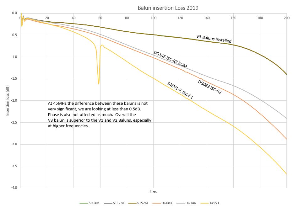
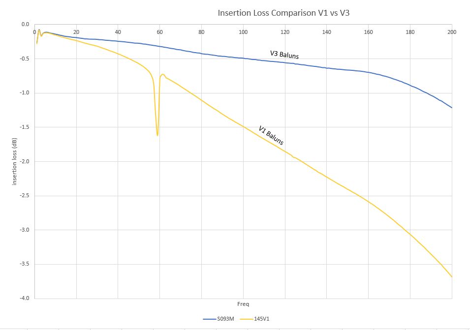
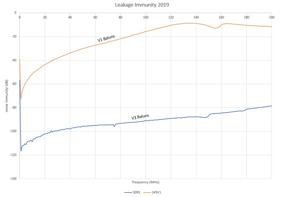
The V1 and V2 baluns on the 45Mhz signals in the LVEA were exchanged with the latest V3 Baluns. Work is recorded on this ALOG-48165 to keep everything nice and tidy.
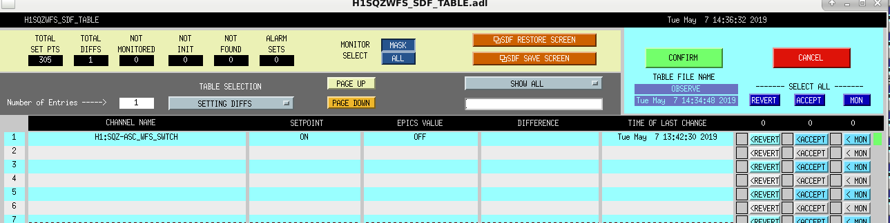
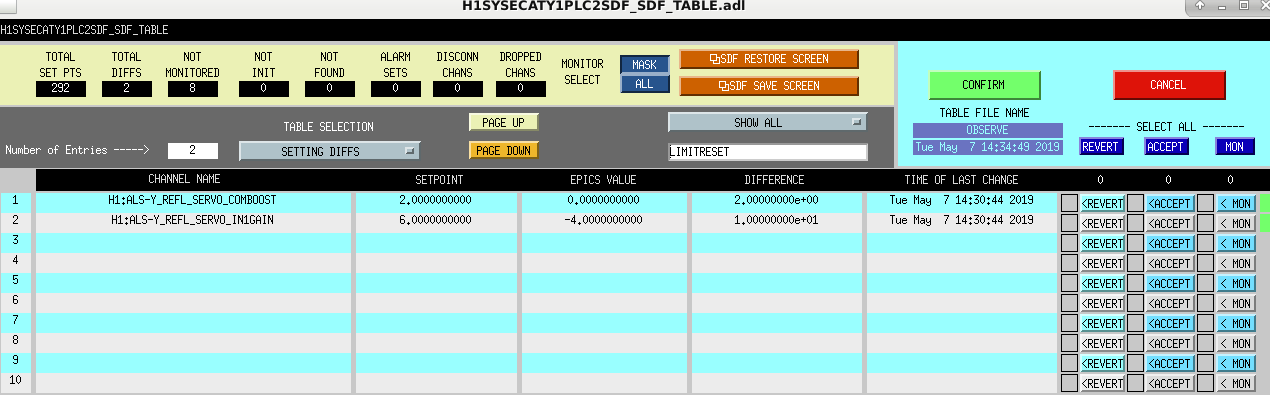
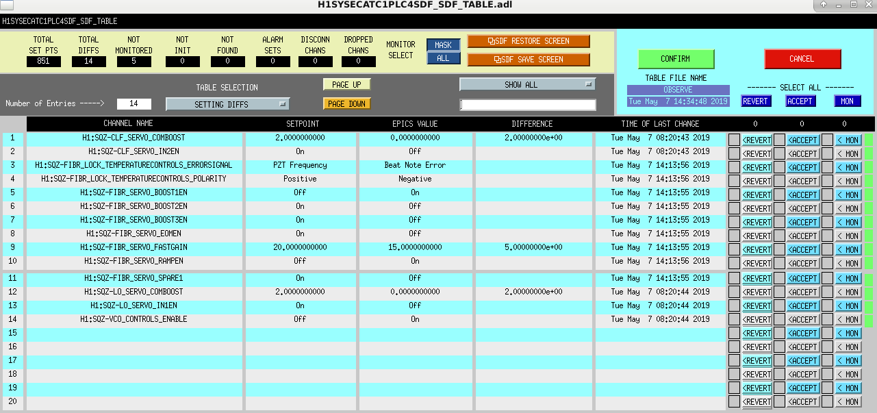
Ran initial alignment and relocked the IFO after the Tuesday maintenance window. Ready to go into Observing after accepting the SDF Diffs in the screen shots posted below.
These squeezer SDFs were fixed and reverted. The squeezer guardian (SQZ_MANAGER) was stuck, and so we weren't injecting squeezing. Even with the SDFs accidentally accepted, the guardian properly prevented us from going to Observing, since the SQZ_MANAGER was not in its nominal state. It turns out that even though JeffB had toggled the squeezer's noise eater on, then off, that wasn't enough to convince the squeezer to lock all the way to injecting squeezing (we tried turning it back off only a few seconds, so that we didn't forget later).
So, I have added to the SQZ_MANAGER guardian to turn ON the squeezer noise eater in the DOWN state, and to turn back OFF the noise eater in the SQZ_ASC state (just before it's nominal state).
I have not yet loaded the SQZ_MANAGER guardian - this should be done next time we are out of Observing for a moment, so that operators no longer should have to deal with this. I am leaving a sticky note with JeffB and his backup Cheryl as a reminder.
I moved the sqz noise eater ON to the Locking_TTFSS state, since it seems like we jump from Squeezing straight to Locking_TTFSS, and don't go through DOWN, so it hasn't been getting turned on.
Cheryl Daniel
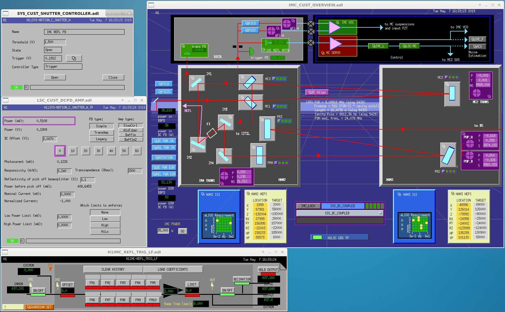
The IOT2L table drawing can be found here: D1300357. We installed a 2" turning mirror after IO_MCR_M3 a the location of IO_MCR_BD2. The beam is sent to the right on the drawing where it encounters a 2" lens with focal lens 100mm. A Thorlabs PDA100A2 was installed somewhat prior to the focus of the beam and acts the trigger PD. Its gain was set to 0dB. A 14mm reflective shutter with was put in front of the IMC LSC PD. When closed the reflected beam is steered onto a razor blade beam dump.
Next we swapped IO_MCR_BS1 with a 90:10 beamsplitter and increased the power using the halfwave plate IO_MCR_HWP1.
The power on the photodetectors before and after:
| in lock |
Before |
Before 35W |
After 1.85W |
After 35W |
|---|---|---|---|---|
| IMC REFL DC | 0.08mW | 1.4mW | 0.54mW | 9.15mW |
| WFS_A DC | 0.037mW | 0.65mW | 0.028mW | 0.46mW |
| WFS_B DC | 0.029mW | 0.51mW | 0.022mW | 0.36mW |
The wavefront sensors seem to have lost about 30% of power, whereas the DC PD power has increased by about 7.
We reduced the IMC IN1GAIN by 20dB. This gives us a ugf around 42kHz. Later in the locking process this gain will be increased by another 3dB which would give us a ugf around ~65kHz. This is a little bit puzzling, since we would expect a 16dB gain to give us the old ugf, which was around 70kHz.
The -20dB was put in the IMC_LOCK DOWN state (for IMC acquisition) as well as lscparams.IMC_IN1_gain. This should be all of the places that the gain is hard-coded. Everywhere else is relative (eg. CARM_TO_ANALOG has a +=3 to add 3dB to whatever is the current value).
I forgot to save a screenshot of the IMC OLG measurement when we had IMC-only (no IFO lock), but that had a UGF of about 41 kHz. (I have the data, but will have to remind myself how to call the plotting scripts...)
Attached is a screenshot of the IMC OLG while the full IFO was locked at Engage_ASC_for_full_IFO, so 2W lock, CARM on its final sensor, DARM still on RF. Looks like ~58kHz after the +3dB from CARM_to_analog.
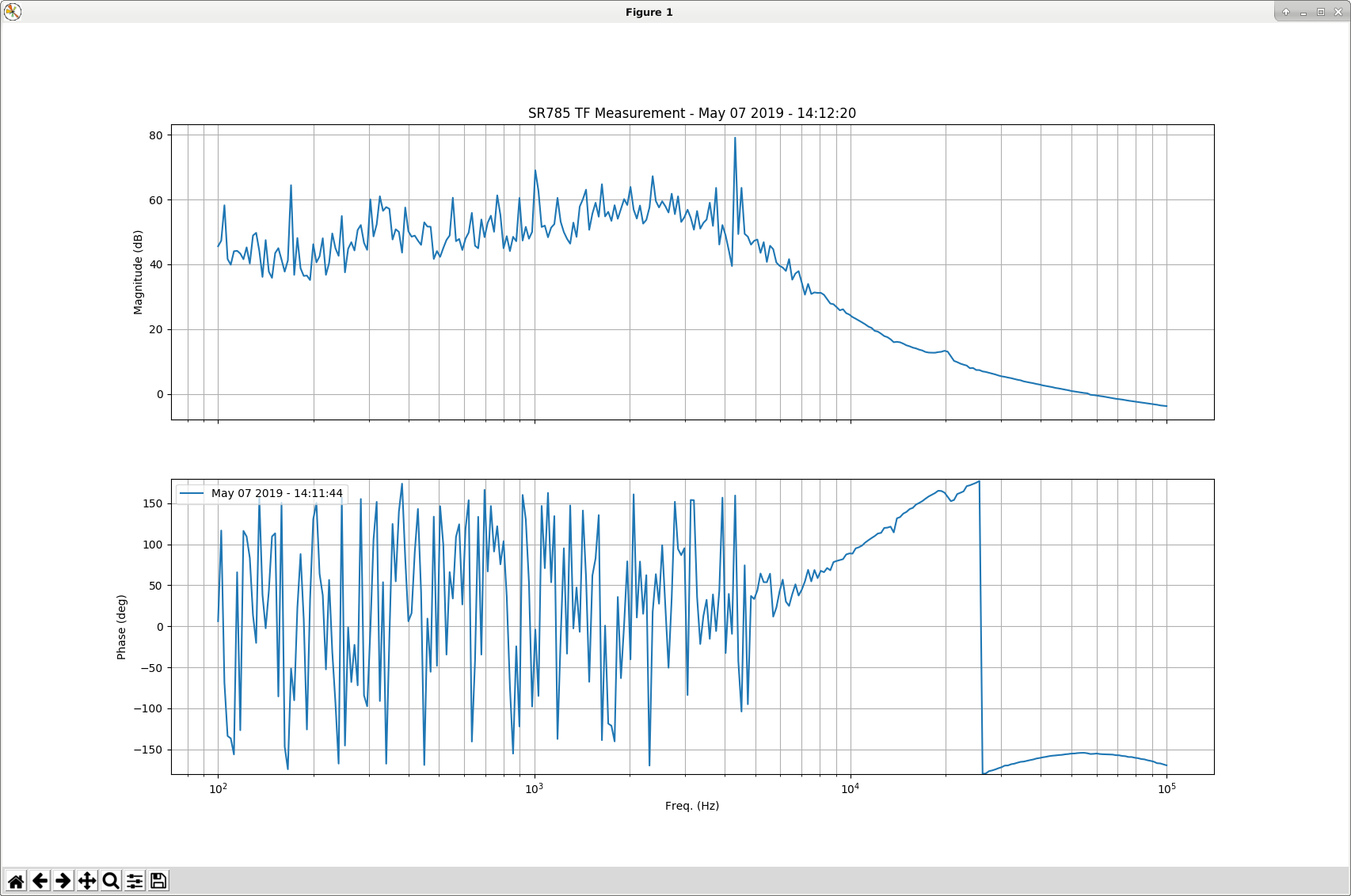
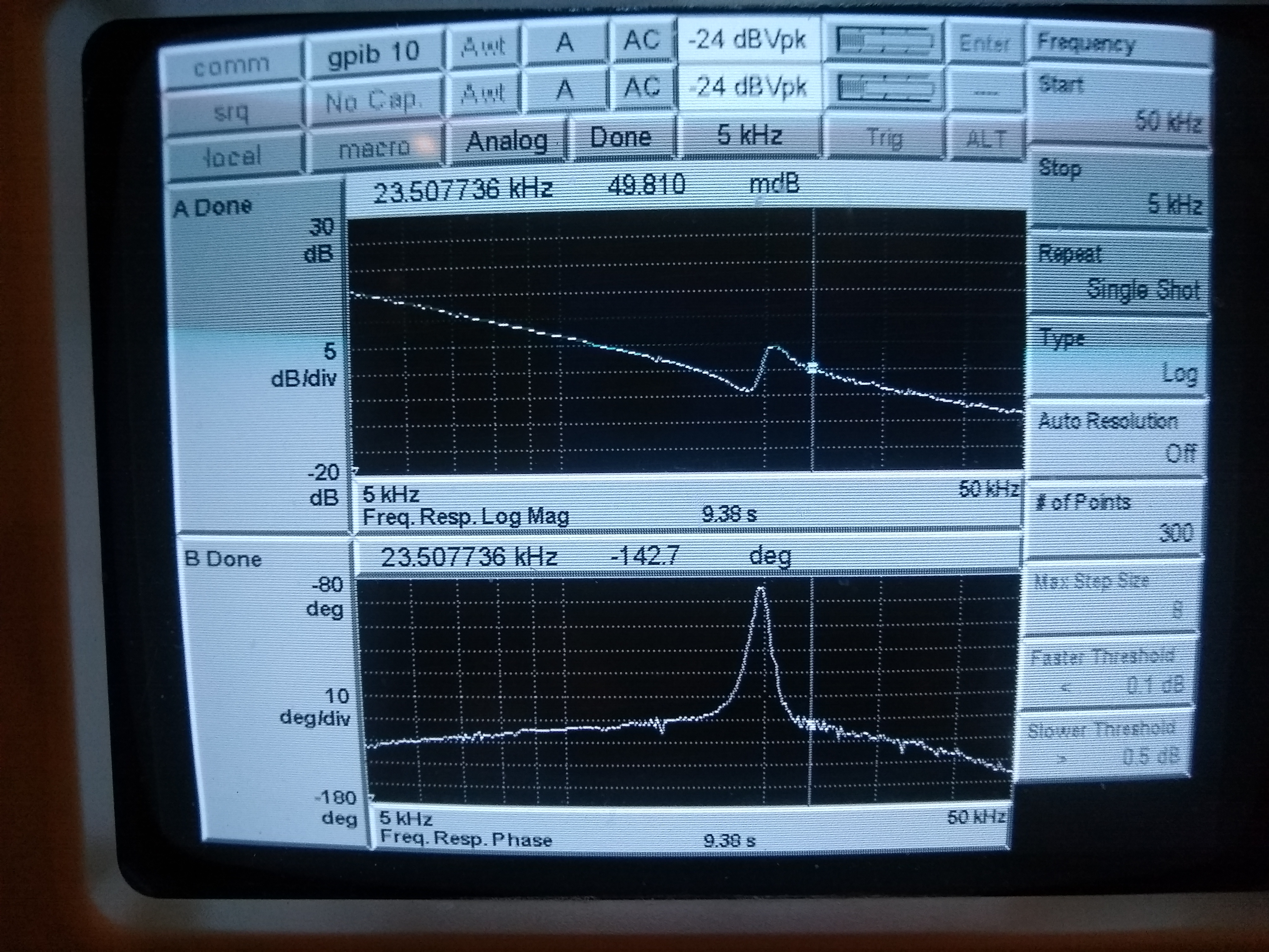
Attached are the IMC and CM transfer functions when fully locked at 35W. The IMC ugf is around 72kHz (excellent phase margin!), whereas the CM ugf is around 20kHz.
This seems to confirm that the optical gain has changed by a factor of 10, whereas the power increase when locked is only around 7. One way to resolve this is with a small amount of light in the wrong polarization incident to the IMC. Due to the halfwave plate most of it would be directed onto the photodetectors, whereas the correct polarization would be attenuated. This would mean the shot noise limited sensitivity has gotten better by approximately 3.8, rather than 2.6 which we would have expected form a factor of 7 increase in power.
Here is a snap shot of the updated medm screens.
Remeasured the error and control spectra of the IMC REFL servo and the LSC REFL servo signals. The IMC signals are mostly the same. The CM servo shows significant improvements at frequencies above ~30Hz. The improvement at 1kHz is a factor of ~5.7, when compare with a lock just 13 hours ago. Since we were only detecting 1.4mW of light previously, the dark noise was probably at a similar level as the shot noise.
Koji and I measured the shot and dark noise levels for the REFL and IMC PDs alog 46552. According to the IMC REFL plot, we were previously limited by dark noise with 1.4 mW on the PD. Now we are squarely in the shot noise limited regime.
M. Pirello, D. Gustafson
We installed new v3 Baluns on the following signals in the CER:
ISC-C3(37-1) 40Mhz TCS AOM Return exchanged v1-117 with v3-S002
ISC-C3(33-4) 158.8Mhz Fiber Beat Note Return exchanged v1-193 with v3-S003
ISC-C3(33-5) 79.4Mhz SQZ VCO Return exchanged v1-151 with v3-S004
ISC-C3(33-6) 203.125MHz SQZ VCXO Return exchanged v1-052 with v3-S005
ISC-C4(39-3) 79.4MHz PSL VCO Return exchanged v1-093 with v3-S010
These are all return signals, the impact should be minimal. Work was completed per WP8150
Balun status can be seen here E1900100.
Continuing the Balun exchange program:
We installed new v3 Baluns on the following signals in the CER:
ISC-C4(39-1) 79.4MHz "ALS DIFF VCO Return" exchanged v1-102 with v3-S006
ISC-C4(39-2) 79.4MHz "ALS COMM VCO Return" exchanged v1-094 with v3-S068
ISC-C4(26-2) 45.5MHz "PEM Readback for Antenna Demod" exchanged v1-055 with v3-S009
ISC-C4(19-8) 9.1MHz "PEM Readback for Antenna Demod" exchanged v1-147 with v3-S116
Work was completed per WP8190. WP was modified to reduce impact to the IFO during this weeks maintenance, we did not touch squeezer.
Continuing the Balun exchange Program:
We installed new V3 baluns on the following 45MHz signals in the LVEA:
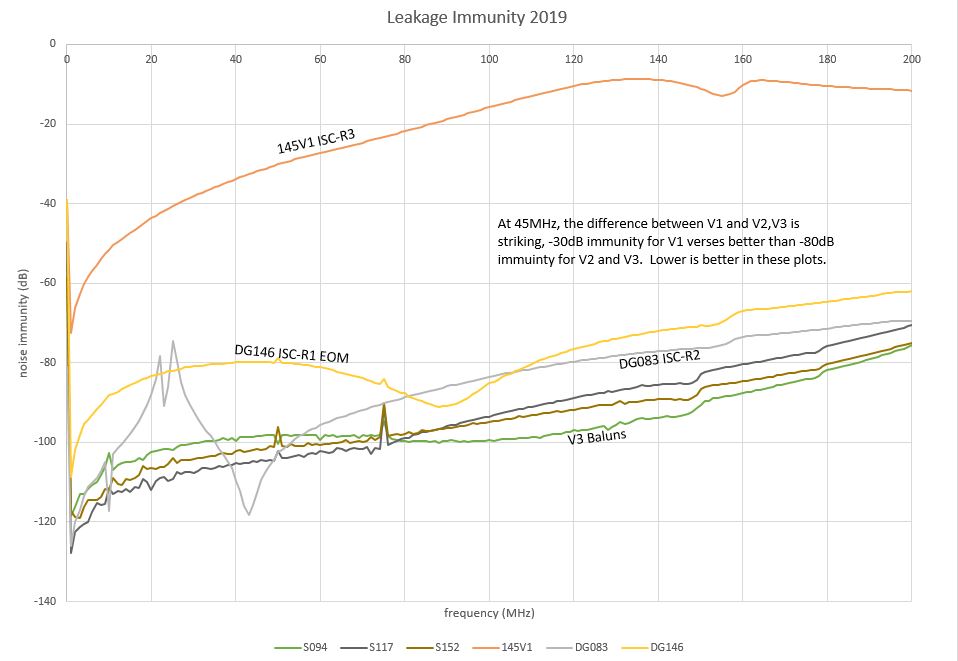
ISC-R1 (41-6) 45MHz Auxiliary Modulation (EOM Driver) exchanged v2-DG146 with v3-S152
ISC-R2 (41-2) 45MHz Distribution exchanged v2-DG083 with v3-S094
ISC-R3 (41-3) 45MHz Distribution exchanged v1-145 with v3-S117
Work was completed per WP8200, balun status can be seen here E1900100.
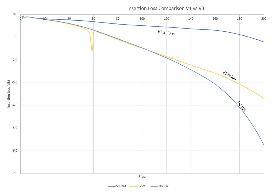
I have attached Insertion Loss and Leakage scans from the old baluns as well as the new ones.
M. Pirello, D. Gustafson
Continuing the Balun exchange Program:
We installed new v3 baluns on the following signals at the PSL racks and at HAM6:
PSL-R2 (18-2) ISS AOM 80MHz exchanged DG-104 with v3-S069
ISC-R3 (41-2) Distribution 4th Harmonic exchanged v1-053 with v3-S160
ISC-R3 (41-4) Distribution 8th Harmonic exchanged v1-091 with v3-S040
ISC-R3 (39-4) Distribution 42.2MHz exchanged v1-125 with v3-S060
Work was completed per WP8215, balun status is in the same place it was last week, E1900100.
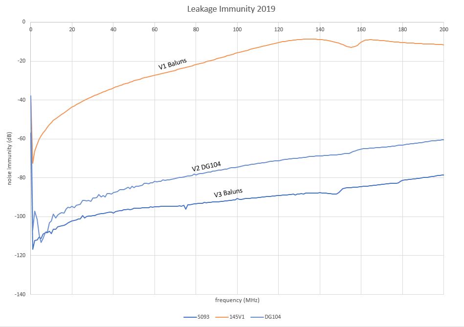
Attached is a comparision between the balun modified by hand (DG-104), and the new v3 balun which replaced it.
M. Pirello, P. King, D. Gustafson
Continuing the Balun exchange Program:
We installed new v3 baluns on the following signals at the PSL racks:
PSL-R2(17-1) FSS Modulation exchanged v1-043 with v3-S157
PSL-R2(17-2) FSS exchanged v1-014 with v3-S093
PSL-R2(17-4) PMC Modulation exchanged v1-021 with v3-S115
PSL-R2(17-5) PMC exchanged v1-050 with v3-S156
PSL-R2(17-6) Injection Locking exchanged v1-084 with v3-S095
ISC-R1(41-2) Distribution JAC Future exchanged v1-159 with v3-S092
** On the last one, the labels on the feed through may be more correct than the DCC. I followed the cable path to the ALS VCO for the PSL.
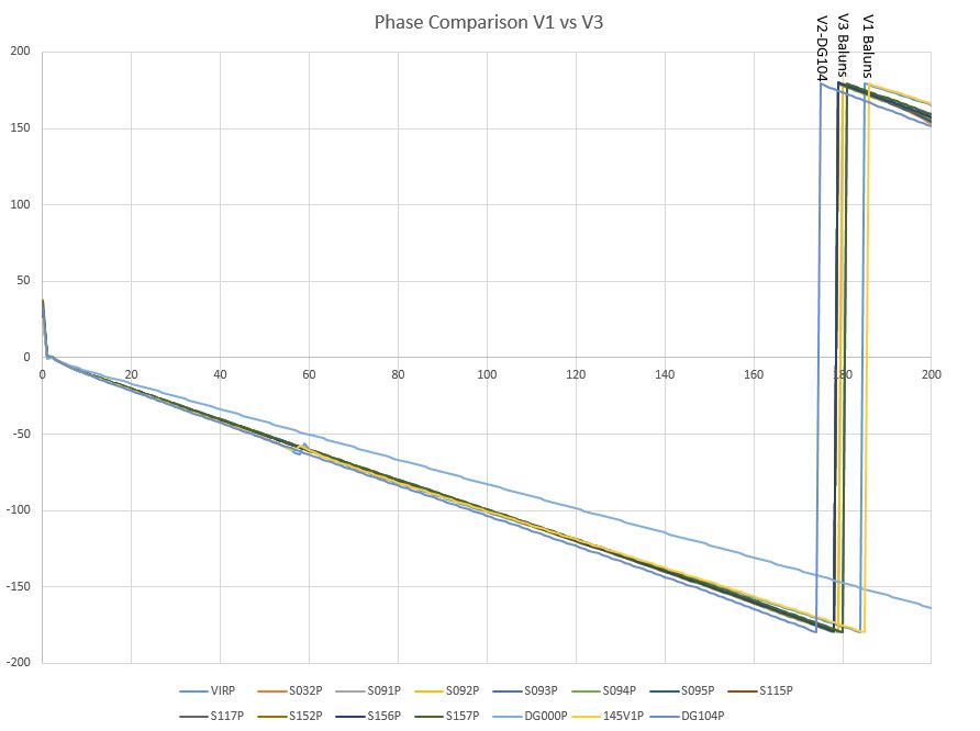
If it is the ALS VCO, Peter told me that it is possibly 80MHz and in this case the difference between V1 and V3 is about 0.75dB more power, and no measurable difference in phase. The PSL signals being under 45Mhz should be less than 1 degree difference in phase, and less than 0.25dB difference in power.
Work was completed per WP8208, balun status is in the same place it was last week, E1900100.
I have attached insertion loss and leakage scans of v1 vs v3 baluns.
We checked the ISC-R1 (41-2) Balun and determined this signal is the REFL_B demod, 9MHz. There should be very little phase & power difference between V1 and V3 baluns at this frequency.
M. Pirello, D. Gustafson
Continuing the Balun exchange Program:
We installed new v3 baluns on the following signals at the end stations.
EX-ISC-C1 (41-5) Return PLL Beat Note 39.5MHz exchanged v1-176 with v3-S050
EX-ISC-C1 (41-6) Return ALS Laser VCO 79.4Mhz exchanged v1-049 with v3-S042
EX-ISC-R1 (41-1) ALS Laser VCO 71MHz exchanged v1-189 with v3-S114
EX-ISC-C1 (41-5) Return PLL Beat Note 39.5MHz exchanged v1-137 with v3-S041
EX-ISC-C1 (41-6) Return ALS Laser VCO 79.4Mhz exchanged v1-199 with v3-S155
EX-ISC-R1 (41-1) ALS Laser VCO 71MHz exchanged v1-039 with v3-S059
Work was completed per WP8222, balun status is in the same place it was last week, E1900100.
M. Pirello, D. Gustafson
Continuing the Balun exchange Program:
We installed new v3 baluns on the following signals at the Squeezer
ISC-R3 (39-1) 80MHz SQZ EOM (OPO) exchanged v1-178 with v3-S082
ISC-R3 (39-2) 35.5MHz SQZ EOM (SHG) exchanged v1-060 with v3-S089
ISC-R3 (39-3) 200MHz SQZ EOM (CLF) exchanged v1-166 with v3-S031
SQZ-R1 (41-1) 80MHz OPO Demodulation exchanged v-122 with v3-S084
SQZ-R1 (41-2) 35.5MHz SHG Demodulation exchanged v1-020 with v3-S033
SQZ-R1 (39-3) 71MHz SQZ VCO Laser Locking exchanged v1-190 with v3-S083
Work was completed per WP8230, balun status is in the same place it was last week, E1900100.
** The 200MHz SQZ EOM CLF signal may require a slight phase change, about 8 degrees difference and 2dB more power with the V3.
M. Pirello, D. Gustafson
Continuing the Balun exchange Program:
We installed new v3 baluns on the following signals at the Squeezer and the PSL racks:
SQZ-R1 (41-3) 3.125MHz SQZ Angle Demodulation exchanged v1-171 with v3-S108
SQZ-R1 (41-4) 3.125MHz SQZ Angle Demodulation exchanged v1-145 with v3-S109
SQZ-R1 (41-5) 6.25MHz CLF Demodulation exchanged v1-183 with v3-S085
ISC-R1 (41-1) 71MHz Distribution exchanged DG-02 with v3-S086
ISC-R1 (41-3) 15th Harmonic Modulation exchanged DG-01 with v3-S058
TCS-MEZ (41-1) TCS exchanged v1-153 with v3-S079
Work was completed per WP8240, balun status is in the same place it was last week, E1900100.
M. Pirello, D. Gustafson
Continuing the Balun exchange Program:
We installed new v3 baluns on the following signals at the field racks near the PSL:
ISC-R2 (41-1) 9MHz Distribution exchanged v1-047 with v3 S019
ISC-R2 (41-3) 2nd Harmnonic Distribution exchanged v1-098 with v3-S019
ISC-R2 (41-4) 3rd Harmonic Distribution exchanged v1-157 with v3-S015
ISC-R2 (41-5) 10th Harmonic Distribution exchanged v1-179 with v3-S016
ISC-R2 (41-6) 15th Harmonic Distribution exchanged v1-074 with v3-S132
ISC-R1 (41-4) 24MHz MC Distribution exchanged v1-040 with v3-S017
ISC-R1 (41-5) 9MHz Main Modulation exchanged v1-033 with v3-S018
Work was completed per WP8244, balun status located at this link: E1900100. This concludes all "known" balun work at the corner station. We are sprinting to next week where we intend to replace the remaining twelve v1 baluns at the end stations.
M. Pirello, D. Gustafson
Continuing the Balun exchange Program, we installed new v3 baluns on the following signals at both end stations:
EX
ISC-R1 (41-2) 24.4MHz Modulation exchanged v1-022 with v3-S074
ISC-R1 (41-3) 24.4MHz Demodulation exchanged v1-184 with v3-S131
ISC-R1 (41-4) Not Connected exchanged v1-064 with v3-S078
ISC-R1 (39-1) 24.4 WFS A Demod exchanged v1-077 with v3-119
ISC-R1 (39-2) 24.4 WFS B Demode exchanged v1-026 with v3-S076
ISC-R1 (39-3) 71 CPS Timing Fanout exchanged v1-059 with v3-S020
EY
ISC-R1 (41-2) 24.4MHz Modulation exchanged v1-127 with v3-S073
ISC-R1 (41-3) 24.4MHz Demodulation exchanged v1-118 with v3-S011
ISC-R1 (41-4) Not Connected exchanged v1-013 with v3-S012
ISC-R1 (39-1) 24.4 WFS A Demod exchanged v1-126 with v3-S075
ISC-R1 (39-2) 24.4 WFS B Demod exchanged v1-161 with v3-S013
ISC-R1 (39-3) 71 CPS Timing Fanout exchanged v1-191 with v3-S135
Work was completed per WP8255, balun status located at this link: E1900100.
** In the process of walking through the LVEA we found 4 more Baluns hidden among the TCS and SUS racks which need upgrading. We were able to upgarde one of these with this Tuesday, and will finish the remainder next maintenance day.
SUS-R3 (40-1) CPS HAM 71MHz exchanged v1-011 with v3-S113
This additional work was started per WP8261
M. Pirello, H. Radkins
The final three baluns were exchanged at the corner this morning for a total of 64 baluns replaced over 14 weeks.
TCS-R2 (41-1) 71Mhz CPS Timing exchanged v1-088 with v3-S144
TCS-R2 (41-2) N/A Empty signal with Balun exchanged v1-081 with v3-S001
TCS-R1 (41-6) TCS Signal from Mechanical Room exhcnaged v1-143 with v3-S045
All work finished per WP8261. This completes work done per FRS9794 and ECR-E1700404 at LHO.
TITLE: 03/08 Day Shift: 16:00-00:00 UTC (08:00-16:00 PST), all times posted in UTC
STATE of H1: Commissioning
INCOMING OPERATOR: None
SHIFT SUMMARY:
Locking went well with the exception of a couple of HEPI pump trips that were physically induced. It was a good exercise and allowed for a small update to the SEI>HEPI wiki instructions for those who are more in the dark about SEI than others
LOG:
16:45 Jeff out to LVEA - shooting pics of ITMs
17:16 Jeff Back
17:24 Kyle out to EY - mechanical room
17:35 Nominal Low Noise - 113.206 Mpc
17:49 LockLoss - EY mechanical room activity tripped HEPI
18:02 Hartmann team (TJ and Daniel) out to LVEA to check SLED
18:06 Jim and Fil to EY to recover HEPI
18:35 Hartmann team back
18:50 Kyle back
18:54 EY HEPI pump recovered - waiting for isolation to resume locking
19:10 EY SEI WDs tripped again
20:03 re-locking resumed
20:49 Nominal Low Noise - 100Mpc
21:33 LockLoss - high bounce mode
22:25 Begin Initial Alignment
22:52 Resume locking
23:50 H1 locked at NLN - 113Mpc
Today I found the pressure relief line of the EndY HEPI full of fluid (a couple feet of 1/2" or something hose.) This is usually an indication to me that the pump station experienced a high pressure event on the output. Attached is a snap of the output pressure and the control signal around 8 March--if this is the time this over pressure occurred it is a pretty good indication of how observant I really am given that I've been there 6 or 8 times since then!
Anyway, the plot shows that several attempts were made at restarting/repowering things after the fuse blow in the above entry. The data shows the output of the controller at max, 2048 while things were reengaged and spiking the pressure and opening the pressure valve letting fluid escape. The last one, I'm not sure why it was different but was at max reading, ~104 psi for 10 to 20 seconds. This is likely the event that filled the relief line with fluid. Looks like time for training!