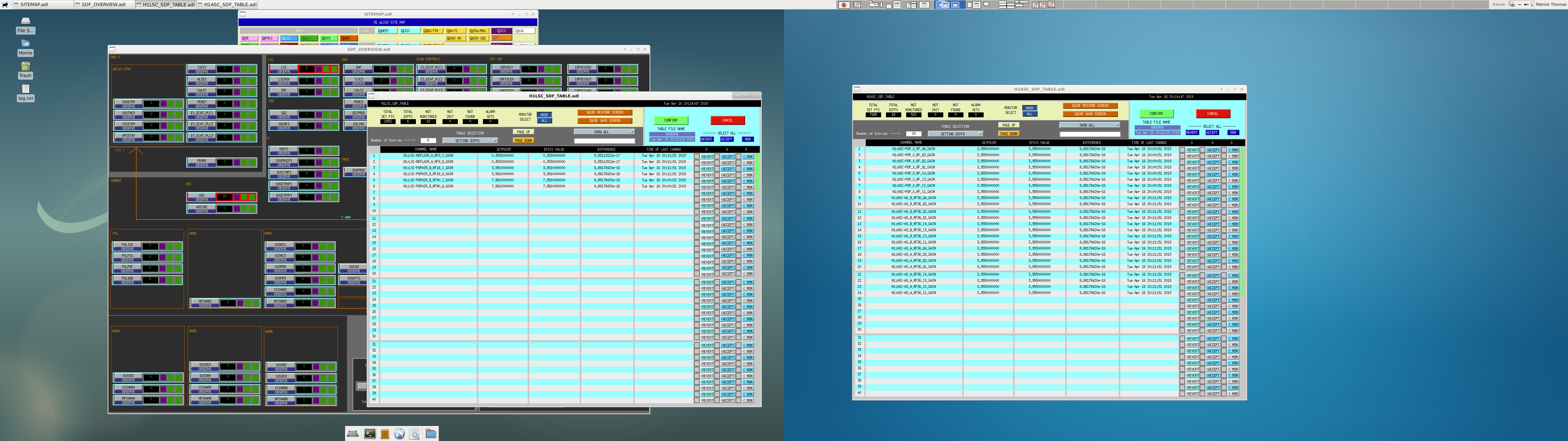
Lock loss. Back to NLN. PEM group running excitations before going back to observing.
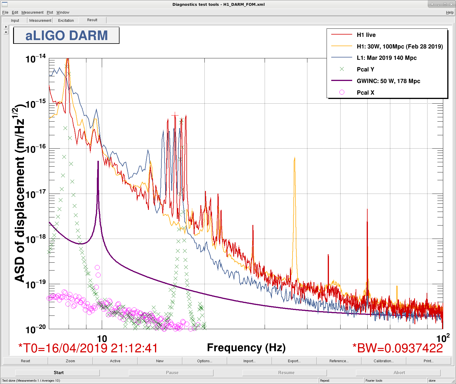
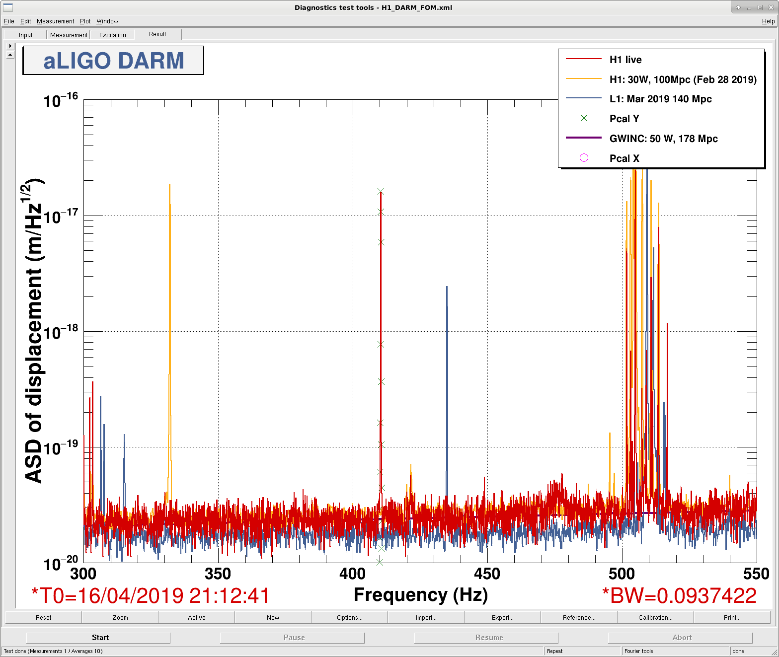
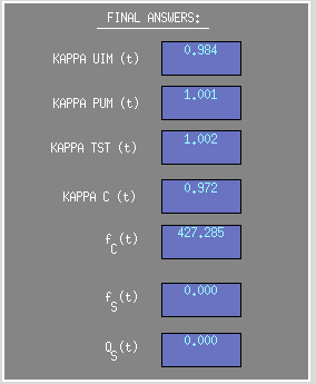
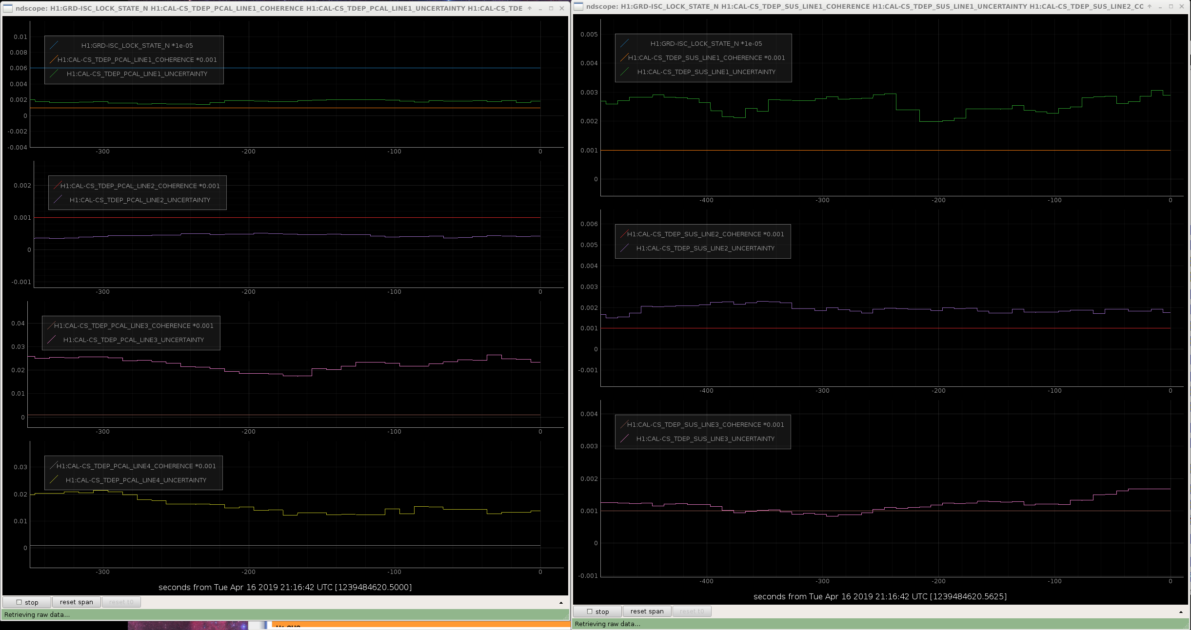
J. Driggers, J. Kissel, A. Viets After a ton of work this morning (see LHO aLOGs 48534, 48530, 48499, 48546, and 48512) - we are now in observation with the newly moved calibration line frequencies, - the interferometer is stable, - the time dependent correction factors calculated from them are reasonable, - the line uncertainties is low, - the GDS-CALIB_STRAIN channel remains corrected for optical gain, cavity pole change, and TST stage actuation strength (but NOT for PUM, UIM, or any optical spring parameters) - the subtraction pipeline has been updated to subtract out these new frequencies. Attached are some relevant screenshots showing the success. - 2019-04-16_H1CALCS_CalibrationLineMove_Success_7to100Hz.png shows the actuator calibration lines at low frequency, now at 15.6 Hz (driven by UIM, L1), 16.4 Hz (driven by PUM, L2), 17.1 Hz (driven by PCALY), and 17.6 Hz (driven by TST, L3) - 2019-04-16_H1CALCS_CalibrationLineMove_Success_300to550Hz.png shows the sensing calibration line, now at 410.3 Hz (driven by PCAL) - 2019-04-16_H1CALCS_CalibrationLineMove_Success_FinalAnswers.png shows the values of the time-dependent correction factors (note that the spring parameters are still bogus) - 2019-04-16_H1CALCS_CalibrationLineMove_Success_Uncertainty.png shows the current levels of uncertainty in the calibration lines. Great work team, and at lightning speed! Later today, while out of observation mode and the PEM team is working on their injections, we intend to further reduce the amplitude of the lines to better compromise uncertainty and noise impact.
TITLE: 04/16 Eve Shift: 23:00-07:00 UTC (16:00-00:00 PST), all times posted in UTC
STATE of H1: Observing at 109Mpc
OUTGOING OPERATOR: Jeff
CURRENT ENVIRONMENT:
Wind: 15mph Gusts, 13mph 5min avg
Primary useism: 0.05 μm/s
Secondary useism: 0.20 μm/s
QUICK SUMMARY:
Locked and in observing. No immediate issues.
Gerardo M., Kyle R.
Following the recent LGV11 actuation failure, analysis and recovery (here is a good place to recap -> https://alog.ligo-la.caltech.edu/aLOG/index.php?callRep=42304), the Project Vacuum Team concluded that all legacy 44" electrically actuated gate valves (at both sites) would need to be visually inspected. This process was started and is continuing as opportunities present themselves (maintenance days). Today we inspected WGV15, WGV14, WGV9, WGV10, WGV17 and WGV18.
Today's results are potentially troubling -> Both SET SCREWS in the CLUTCH BODY of WGV10 were found to be very loose -> I tightened these (2 turns) but was torque-limited to a few inch*pounds by the L-key used. I don't have a torque specification even if I did have the proper tool. Also, the clearance between the RETAINING NUT and LIMIT SWITCH PULLEY was noticeably greater than that of the other valves. By chance, one of the two DRIVE SHAFT BALL NUT SET SCREWS was accessible on WGV14 and it was found to be quite loose -> This was tightened using an L-key to a few inch pounds. The CLUTCH BODY of WGV17 differed from any of the other units seen thus far in that its SET SCREWS are oriented (machined) at 90 degrees to each other versus 180 degrees for the other units. Finally, WGV18's CLUTCH PRE-LOAD was at "8" on the graduated scale. This compares to the more typical values of 4 or 5 -> This may be due to the placement of the graduated scale on this unit and may not translate into a meaningful PRE-LOAD difference as the number of exposed thread crests seen is typical of the other units.
The archived results of these inspections is kept in the DCC in Q1800019 (thanks Stephen A.).
Today I revisited GV10 (this time with hand held lighting) and found that the "gap" initially observed was nothing more than the chamfer machined on the retaining nut.
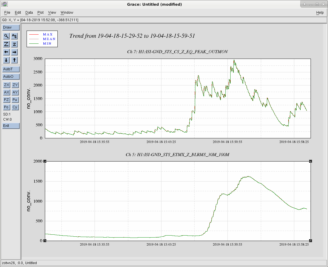
BrianL has been working on new code to make it easier to see when earthquakes are actually arriving on site. I won't go into details of the new code, but the idea is to take the CS STS Z ground velocity and do some more clever band-passing of it to get a better real-time measure of peak velocity in the earthquake frequency band. If anyone is interested, Brian's install document T1900149 gives a more complete story, the approved ECR is E1900108. This morning I installed the part in SEIPROC and it is running now.
The problem with the already existing ground STS BLRMS on the wall FOMs we have been using is that the rise time of the .03-.1hz bandpass filter is on the order of 2 minutes, which means that often the earthquake has passed before we see anything on the wall. This new code should only lag by a few seconds at most. Brian's document covers a few example earthquakes.
I have added some links to the ISI_CONFIG screen to access the filters and some displays for this new code. In the bottom right corner of the ISI_CONFIG screen there are 3 new buttons: the SEISMON overview, a screen that Brian made for this peak ground velocity monitor code and an ndscope template for the eq band peak velocities. The ndscope should be sufficient for most control room uses, and is more flexible than the MEDM.
Having just installed this, I don't have any real guidance yet, but I would expect that when Seismon or verbal gives notification of an incoming earthquake, it would be useful to have the ndscope up to see if this peak velocity monitor gives better early warning of the earthquake than, say, IFO control signals.
This is a comparison between the eq band blrms and the new eq velocity monitor for the 6.5 from "Australia" yesterday. The new monitor gives a better indication that the earthquake is actually starting to shake the site, as it starts moving up about 2 minutes before the blrms really shows any difference. It would be worth comparing this to some IFO channels,. but I think Jeff had already switched SEI_CONF at this point, so things were already noisier.
At the end of Maintenance Day today, started VEA Sweeps. PEM has APPROVED hours for injections this week, so there are PEM set-ups which are allowed this week. With that said:
Relocked after Tuesday maintenance. IFO is back into Observing with a range of 1067.4Mpc.
Range is really 107.6Mpc.
[M. Wade, J. Driggers, J. Kissel, A. Viets]
I restarted the primary and redundant GDS calibration pipelines around GPS time 1239481300 with new filters and calibration line frequencies (see LHO aLOG 48546). The filters were made using the new calibration model of LHO aLOG 48534. CPU usage and latency look normal.
[M. Wade, J. Driggers, J. Kissel, A. Viets]
I've produced new filters for the GDS calibration pipeline based on the calibration model made earlier today (see LHO aLOG 48534). The main changes were:
The filters were produced in SVN revision 7252, and can be found here:
aligocalibration/trunk/Runs/O3/GDSFilters/H1GDS_1239476409.npz
They were produced using the script
/ligo/svncommon/CalSVN/aligocalibration/trunk/Runs/O3/H1/Scripts/TDfilters/H1_run_td_filters_1239476409.sh
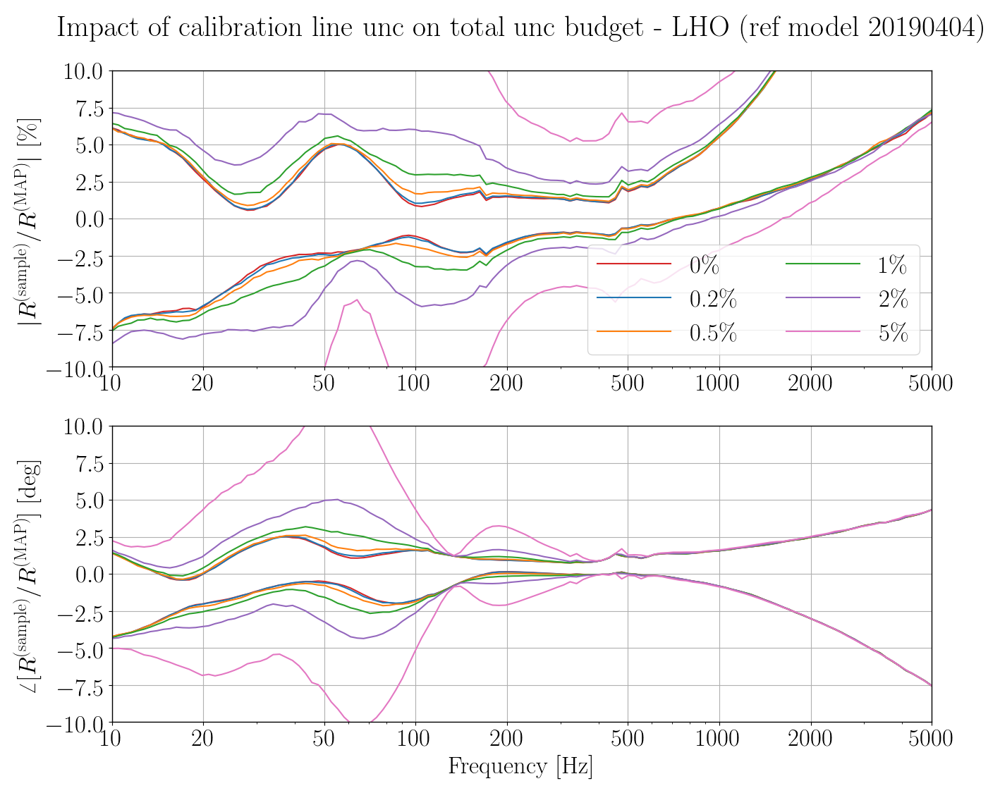
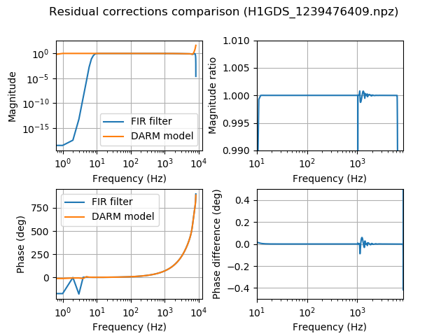
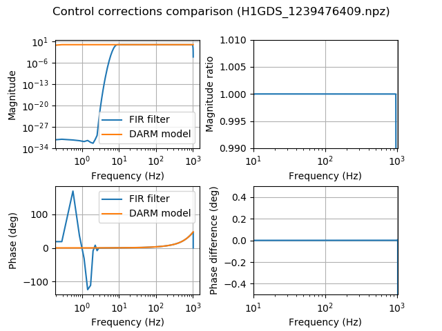
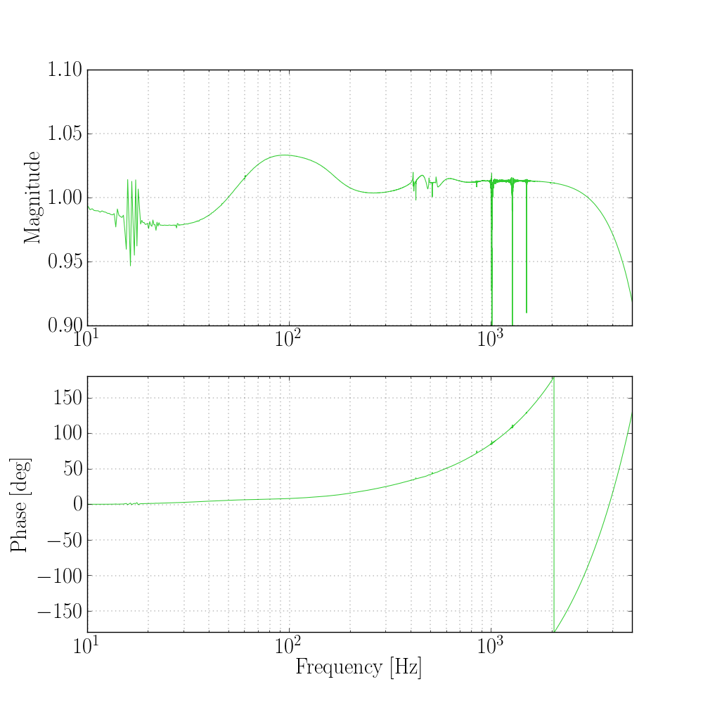
Bode plots of the correction filters for the inverse sensing path and actuation path are attached. They agree with the model to the expected level. More plots will be added soon, once we have some low-noise data after the update to work with.
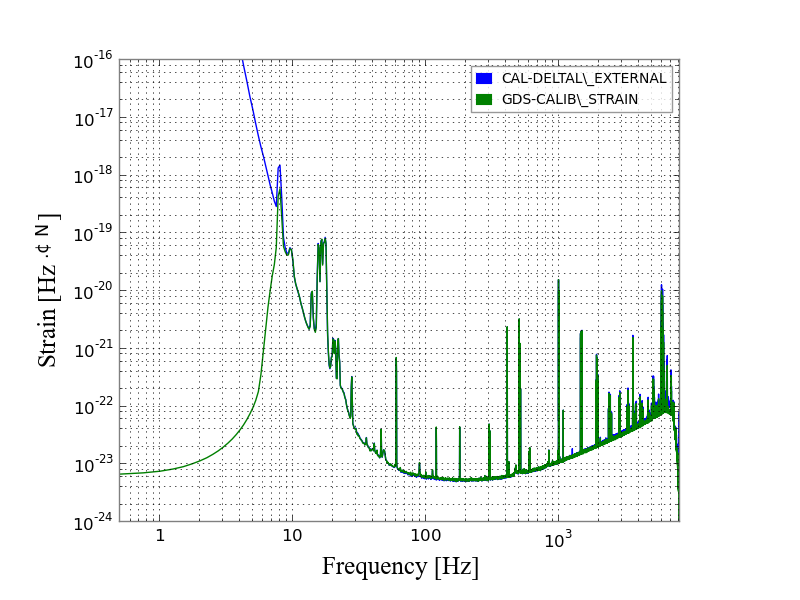
Using data from the first lock stretch after the calibration model and line frequencies were updated, I have made several more diagnostic plots:
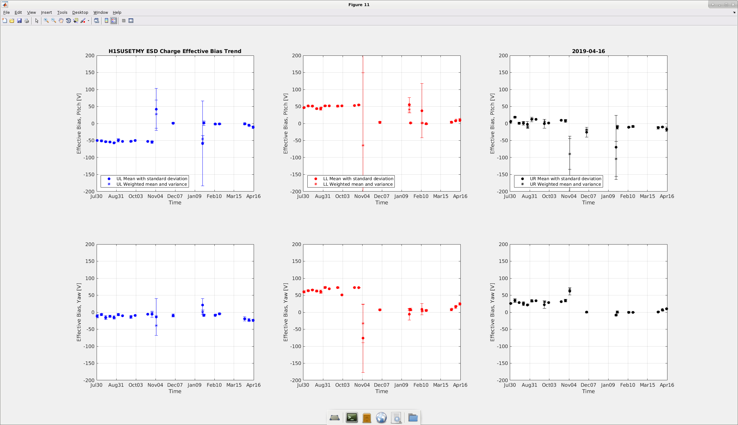
Results from today's OPLEV charge measurements for both ETMX and ETMY is attached below. No major difference from last week as the effective bias looks to be within tolerance.
All the values were restored after the measurement was complete.
WP 8069
Terminated cables that will be used to remotely control the ISCTEY table lights, TCS Sled driver and monitor table fan status. Same work that was done at EX.
WP8166 fix h1oaf1 timing slips, new IPC channels from quad sus to calcs
Jenne, Jeff, Dave:
New h1susetmx, h1susetmy, h1susitmx, h1susitmy and h1calcs models were installed. Three new IPC channels from each SUS to CAL were added (local Dolphin for ITMs, long-range Dolphin for ETMs). DAQ restart was required for all 5 models (SUS had some TEMP channels removed, adding IPC senders does not change DAQ).
WP8176 C-Code change for h1seiproc
Jim, Dave:
h1seiproc was restarted with a new version of the PEAK_MON.c code. No DAQ restart was required.
WP8168 h1sqz channel rename
Sheila, Dave:
A new h1sqz model was installed to fix three channels with bad naming.
H1:SQZ-DCPD_RATIO_[2-4]_dB_MON changed to H1:SQZ-DCPD_RATIO_[2-4]_DB_MON (dB becomes DB)
To preserve raw minute trend data for these channels, I renamed the minute_trend files for these three channels when the DAQ was being restarted. I verified this was successful by trending the new channels over the past month.
WP8174 Beckhoff SQZ PLC4 code changes
Daniel, Dave:
Daniel made changes to h1ecatc1plc4 code. We found that the sdf for this system had stopped, so I restarted h1sysecatc1plc[1-4]sdf systems on h1ecatmon0. A new H1EPICS_ECATC1PLC4.ini was created. A DAQ restart was required.
DAQ Restart(s)
Dave:
First DAQ restart was for h1susetmx, h1susetmy, h1susitmx, h1susitmy, h1calcs and h1sqz model changes. It was a messy restart, mx_stream went bad for h1sush2a (h1susmc[1,3], h1suspr[m,3]) which required a start_streamer to fix.
Unfortunately at this point I realized I had not restarted the external EDCU (h1edc) to sync to the new Beckhoff changes, so...
DAQ restart number 2. This time a regular clean restart for new h1edc channel configuration.
Per work permit 8169. I installed Teflon sheets in between the cable trays and the cable tray supports attached to the Ham6 racks. It is hard to say we have great isolation as a number of signals are grounded in chamber thus preventing complete isolation. Next vent when we fix the in chamber problems hopefully the rack isolation will help with our 60Hz peaks.
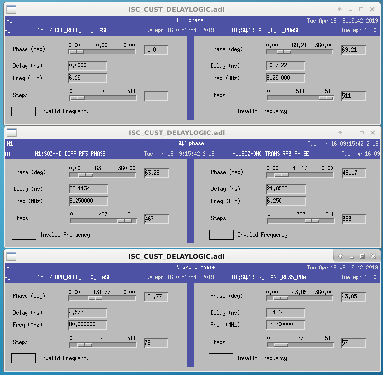
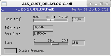
Since some time we had connected 4 phase shifters in series for the CLF demodulator (CLF_REFL_RF6, OMC_TRANS_RF3, HD_DIFF_RF3 and SPARE_D_RF) and none in the OMC and homodyne paths. This update consolidates the 4 delay phase shifters into a single CLF_REFL_RF6 unit that has 4 times the range. The slow controls channels for the HD_DIFF_RF3 and SPARE_D_RF units are gone.
Since we've had more mode hopping of the squeezer laser in the last few days, I went out this morning to change the current and temperature settings.
Initial settings: 1.936 A, 33.72C Final settings: 2.107A, 31.68C
Before starting, I could clearly see that the laser was mulitmode by scanning the SHG. Increasing the laser current slightly (2.015A) was enough that I could no longer see the second mode, but the beat note dropped in strength to -25dBm at the PFD monitor, and it became difficult/imposible to move the laser temperature to bring back the beatnote. Watching the SHG scan, I moved the current up without following with the temperature, and found that it just started to become multimode when the current reached 2.234A, near the max.
I set the current to about half way between the two places where I saw mode hopping, 2.107A, which is fairly close to what Nutinsee had in January 46587 (around 33.67C). When we found the beatnote there it was very small and seemed to move a lot, so we tried a large temperature search, and found a good beatnote at 31.68C.
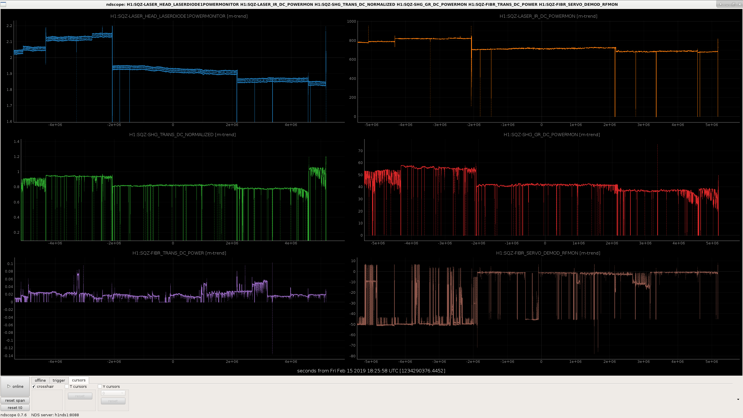
The attached screenshot shows a history of the mode hopping behavoir of this laser over the last several months, each time the SHG trans and green power monitors become noisy, we adjust the laser current, and things are better for a while before it starts hopping again. It seems that the change last week (48361) didn't help much.
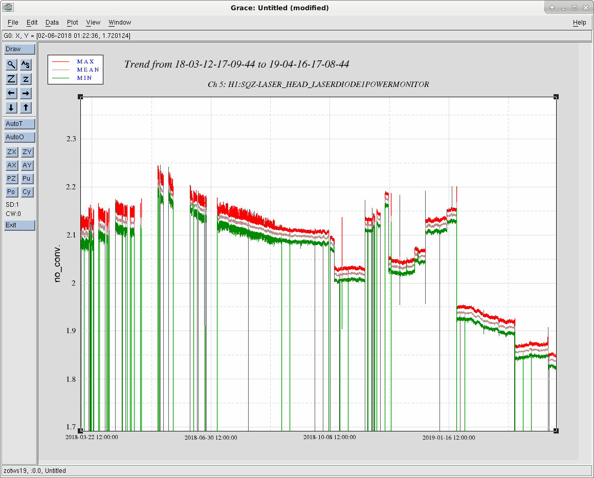
This is the laser diode current plotted over the past 400 days. The jumps are associated with our tweaking. We might expect the current to be constant in between, but it isn't.
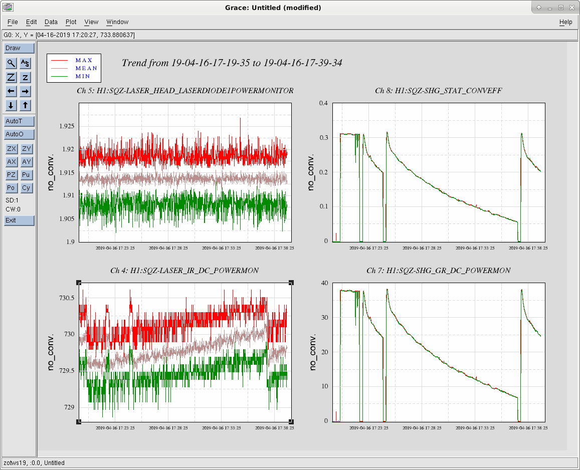
This plot shows a couple of SHG locks during a 20 minute period with a bad diode laser current. The SHG initially locks with high conversion efficiency which then drifts down over several minutes. Once relocked, it starts again at high efficiency. While the laser diode current is stable, we see a correlation with the laser output power. I am wondering, if we are back feeding some of the SHG reflected light which in turn aggravates our mode hopping problems. We should consider a second Faraday isolator in the IR path.