Displaying reports 41901-41920 of 88750.Go to page Start 2092 2093 2094 2095 2096 2097 2098 2099 2100 End
Reports until 20:40, Saturday 06 April 2019
H1 General
yannick.lecoeuche@LIGO.ORG - posted 20:40, Saturday 06 April 2019 (48291)
Ops Mid-Shift Summary

Been in Observing for ~2 hours, minus a brief drop out when I turned off the ADS lines to try and get ahead of a DCPD glitch (ADS lines are back on now). Wind is receding, microseism has leveled off at ~0.3 um/s.

H1 SUS
yannick.lecoeuche@LIGO.ORG - posted 18:00, Saturday 06 April 2019 (48290)
Changing ENGAGE_DAMPING Violin Mode Guardian States

[Craig, Niko]

We noticed the violin damping node was taking a long time to reach its nominal state after hitting NLN. Craig is changing the wait flag to be false for all ramp_gain to fix this.

H1 CDS
jonathan.hanks@LIGO.ORG - posted 17:16, Saturday 06 April 2019 (48289)
GPS week number rollover event was uneventful

Dave, Jonathan, Niko,

The GPS week number rolled over today at 16:59:42 localtime.  We monitored the system as the rollover happened.  There were no errors observed.

Items that we checked (from T1990166):

After the rollover the gps time read good on the frontends, dc0, the wall clock and the system times look good on the workstations.  We will need to check the ntp settings on dc0, it appears to be off.  That will be a Tuesday task.

The trimble showed a 2048 week counter, which showed it handling the 2nd rollover in GPS just fine.

H1 General
jeffrey.bartlett@LIGO.ORG - posted 16:25, Saturday 06 April 2019 - last comment - 10:19, Monday 17 June 2019(48288)
Ops Day Shift Summary
Ops Shift Log: 04/06/2019, Day Shift 15:00 – 23:00 (08:00 - 16:00) Time - UTC (PT)
State of H1: Relocking after environmental lockloss
Intent Bit: Aligning
Support: N/A
Incoming Operator: Niko  
Shift Summary: Caltech alumni lunch and site tour. Lost lock due to high local winds and surf on coast. Started Initial Alignment. Got ALS locked and off loaded. Then three earthquakes in Temo-Leste (mag 6.3, 6.0, and 4.7), switch to EARTHQUAKE on SEI_CONFIG. Having trouble with Input Align, when turned over to Niko.      
 
Activity Log: Time - UTC (PT)
15:00 (08:00) Take over from Patrick
16:30 (09:30) Amber – On site to setup for Caltech alumni lunch and tour
15:52 (10:52) GRB – Confirmed alert with LLO - L1 and V1 are down
18:04 (11:04) Caterer on site to setup for Caltech Alumni lunch in MPR
19:15 (12:15) Caltech tour in MSR
21:06 (14:06) Lockloss – High winds, coastal microseism, and earthquake
21:25 (14:25) Caltech alumni tour in CR
21:48 (14:48) Tour out of CR
22:15 (15:15) Caltech alumni tour in CR
22:35 (15:35) Tour out of CR
22:50 (15:50) Set SEI _CONFIG to EARTHQUAKE for 6.3, 6.0, and 4.7 mag quakes in Temor-Leste
23:00 (16:00) Turn over to Niko



Comments related to this report
jeffrey.kissel@LIGO.ORG - 10:19, Monday 17 June 2019 (49995)DetChar, SEI
Tagging @DetChar and SEI for data in seismic's sensor correction configuration transition studies.
H1 General
yannick.lecoeuche@LIGO.ORG - posted 16:09, Saturday 06 April 2019 (48287)
Ops EVE Shift Transition

Ops Shift Transition: 04/06/2019, Eve Shift 23:00 – 07:00 (16:00 -00:00) - UTC (PT)

State of H1: Initial Alignment

Intent Bit: Commission

Weather: Clear skies. Winds are up to 10 and 30 mph today.

Primary 0.03 – 0.1Hz: 0.5 um/s

Secondary 0.1 – 0.3Hz: 0.3 um/s

Outgoing Operator: Jeff

Quick Summary: Fast earthquake knocked out LHO and LLO, high wind and microseism has convinced us to start an initial alignment.

H1 General
jeffrey.bartlett@LIGO.ORG - posted 12:12, Saturday 06 April 2019 (48286)
Ops Day Mid-Shift Summary
   IFO in Observing for the past 14.5 hours. Microseism is rising due to local winds and coastal storm driven waves. Range is bouncing between 106 and 112 Mpc. No other issues or concerns. 

   Had one GRB alert.  

   Caltech alumni group on site lecture, lunch, and tour.    
H1 General
jeffrey.bartlett@LIGO.ORG - posted 08:12, Saturday 06 April 2019 (48285)
Ops Day Shift Transition
Ops Shift Transition: 04/06/2019, Day Shift 15:00 – 23:00 (08:00 -16:00) - UTC (PT)
State of H1: Locked at NLN
Intent Bit: Observing
Weather: The skies are overcast with intermittent rain in the forecast during the day. The winds are currently up to a Light Breeze, but could be gusting into the 20s to 30s mph. Temperatures should be in the mid-60s.    
Primary 0.03 – 0.1Hz: 0.05um/s
Secondary 0.1 – 0.3Hz: 0.5mu/s
Outgoing Operator: Patrick
Quick Summary: IFO has been locked in observing for the past 10.5 hours. The range is 111.8Mpc. Environmental conditions are good. No issues or concerns at this time.
LHO General
patrick.thomas@LIGO.ORG - posted 08:01, Saturday 06 April 2019 (48284)
Ops Owl Shift Summary
TITLE: 04/06 Owl Shift: 07:00-15:00 UTC (00:00-08:00 PST), all times posted in UTC
STATE of H1: Observing at 113Mpc
INCOMING OPERATOR: Jeff
SHIFT SUMMARY: Locked and in observing entire shift. No issues to report.
LOG:

10:47 UTC GRB notification (E329056). Confirmed with LLO.
11:10 UTC GRB notification (E329057). Confirmed with LLO.
12:09 UTC Restarted video0
LHO General
patrick.thomas@LIGO.ORG - posted 04:02, Saturday 06 April 2019 (48283)
Ops Owl Mid Shift Status
Have remained locked and in observing. No issues to report.

10:47 UTC GRB notification (E329056). Confirmed with LLO.
LHO General
patrick.thomas@LIGO.ORG - posted 00:11, Saturday 06 April 2019 (48282)
Ops Owl Shift Transition
TITLE: 04/06 Owl Shift: 07:00-15:00 UTC (00:00-08:00 PST), all times posted in UTC
STATE of H1: Observing at 111Mpc
OUTGOING OPERATOR: Niko
CURRENT ENVIRONMENT:
    Wind: 16mph Gusts, 12mph 5min avg
    Primary useism: 0.05 μm/s
    Secondary useism: 0.38 μm/s 
QUICK SUMMARY:

Wind has come down. Microseism has leveled out, but is high.
H1 General
yannick.lecoeuche@LIGO.ORG - posted 00:01, Saturday 06 April 2019 (48281)
Shift Summary - Evening

TITLE: 04/05 Eve Shift 23:00 – 07:00 (16:00 -00:00), all times posted in UTC

STATE of H1: Observing at 110 Mpc

INCOMING OPERATOR: Patrick

SHIFT SUMMARY: Had a few hours of Observing at the beginning of the shift. High wind/microseism knocked us out of lock and prevented the IFO from re-locking for a while. Tried MORE_WINDY and VERY_WINDY_NOBRSXY seismic configurations with not much luck (probably due to the microseisms). It finally down enough to let us relock at 04:45. Leaving the IFO in Observing for ~2 hours. Total Observing time during the shift is a little under 5 hours.


LOG:


23:00 (16:00) Start of shift

23:46 (16:46) At NLN, entering Observing mode

23:49 (16:49) Knocked out of NLN by another wind spike, at around 50 mph

00:42 (17:42) Entering Observing Mode

03:10 (20:12) Lost lock due to high wind and microseism

04:45 (21:45) Back in Observing

07:00 (00:00) End of shift

H1 SQZ
yannick.lecoeuche@LIGO.ORG - posted 20:20, Friday 05 April 2019 (48279)
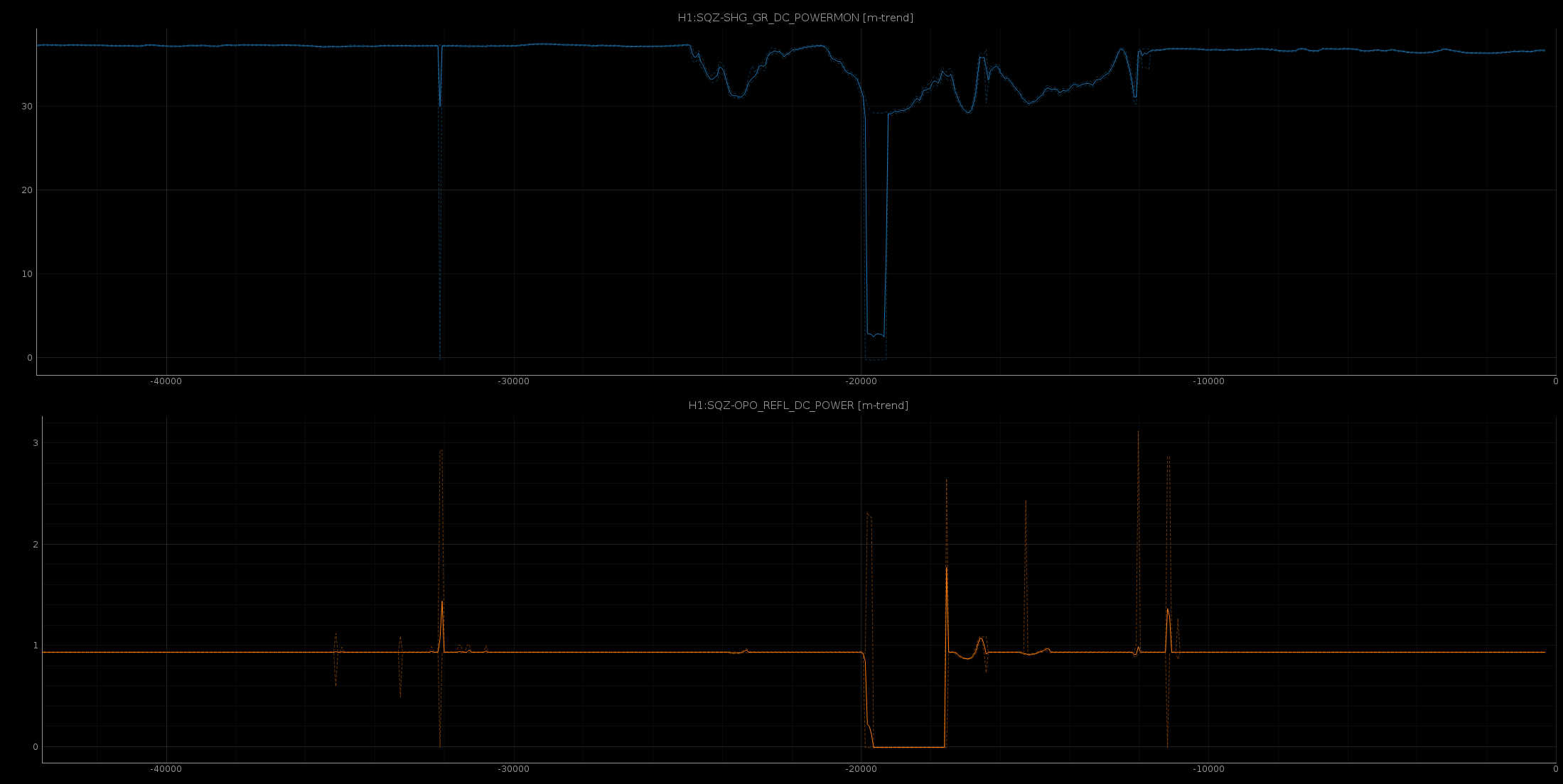
SQZ channel day trend

Day trend of H1:SQZ-SHG_GR_DC_POWERMON and H1:SQZ-OPO_REFL_DC_POWER, at Nutsinee's request.

Images attached to this report
H1 General
yannick.lecoeuche@LIGO.ORG - posted 20:06, Friday 05 April 2019 (48278)
Ops Mid-Shift Summary

After a brief wind spike knocked us out of Observing mode at 23:49 (16:49), we reacquired lock and have been in Observing for ~2 hours. Weather has cleared and wind has died down a bit increased significantly.

H1 CAL
sheila.dwyer@LIGO.ORG - posted 19:20, Friday 05 April 2019 - last comment - 12:12, Wednesday 10 April 2019(48276)
correcting CALCS for response function, 0.95 scale factor in actuator can be removed

There are several things that the CALCS calibration doesn't correctly calibrate, which are corrected later in the GDS calibration.  As Jeff and Lili wrote in a dcc document yesterday, T1900169, if the real sensing function C = dC*C' where C' is the sensing function implemented in CALCS, and A=dA*A', then the correction that needs to be applied to the front end calibration R/R' = 1/delC*(1+CAD)/(1+CAD/(delA delC))  What is currently implemented (for example in the calibration of dtt templates) is just 1/delC, which is fairly different from the R/R' correction.  The first attached pdf shows the difference between 1/delC and the full response function correction for the pyDARM model from April 2nd. 

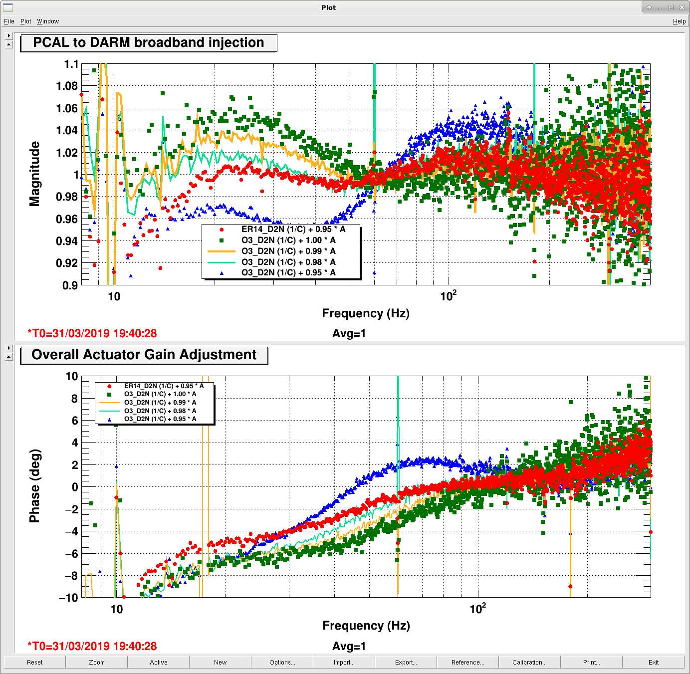
On March 31st, 48102 CAL CS filters based on the sensing and actuation measurements were installed, and checked with a boardband pcal to DeltaL measurement. (green squares in this plot). We are now very unsure about the calibration applied in this DTT template, but last week it was used to adjust the calibration, all the acutator gains were scaled by 0.95 to make the result from this template seem closer to 1 (red dots in the plot).

Today we took the data from the time of the broad band injection with the correctly fit CALCS filters installed, exported it with no calibration applied by dtt, and removed the whitening and 2 1Hz poles for the pcal response in meters, which results in the orage dots in the second pdf (delta L/pcal meters without correcting R).  This reproduces the result from the dtt template fairly well, with an apparent 4% systematic error from 20-30 Hz, where the dtt template shows 5%.  Applying the R/R' correction to this measurement, the apparent systematic error is reduced. 

The script used to produce this plot is in the CALSVN /O3/H1/Scripts/CALCS_FE/process_broadband_pcal_20190331.py  I have used the outputs of pyDARM for the corrections to the sensing function and the actuation function, but the calibration group has been checking these functions throughly, and Jeff is writing an alog right now about what they have found.  Once we are confident about the corrections produced by pyDARM we can rerun this script.

For now it seems like we can take the 0.95 scale factor out of CALCS.  


Non-image files attached to this report
Comments related to this report
ling.sun@LIGO.ORG - 09:11, Tuesday 09 April 2019 (48335)

I've added an updated plot including the results of correcting 1/deltaC only.

There are two minor updates, which do not impact the overall results:

1) R/R' should be 1/delC * (1 + CAD delA delC) / (1+CAD) rather than 1/delC*(1+CAD)/(1+CAD/(delA delC)) [see T1900169]

2) Using the 20190328springfix model, the one installed in CAL-CS when taking the green BB measurements.

The actuation correction only curve explains why the green squares became blue triangles in this BB plot when tuning the actuation amplitudes. But the phase still does not match what we see in this BB plot.

Non-image files attached to this comment
ling.sun@LIGO.ORG - 12:12, Wednesday 10 April 2019 (48383)

Clarification: the last comment "R/R' should be 1/delC * (1 + CAD delA delC) / (1+CAD) rather than 1/delC*(1+CAD)/(1+CAD/(delA delC))" was wrong. I misunderstood the original parameters. Sheila's equation was the correct one. But the results are still the same.

H1 SQZ
sheila.dwyer@LIGO.ORG - posted 17:14, Friday 05 April 2019 - last comment - 20:10, Friday 05 April 2019(48274)
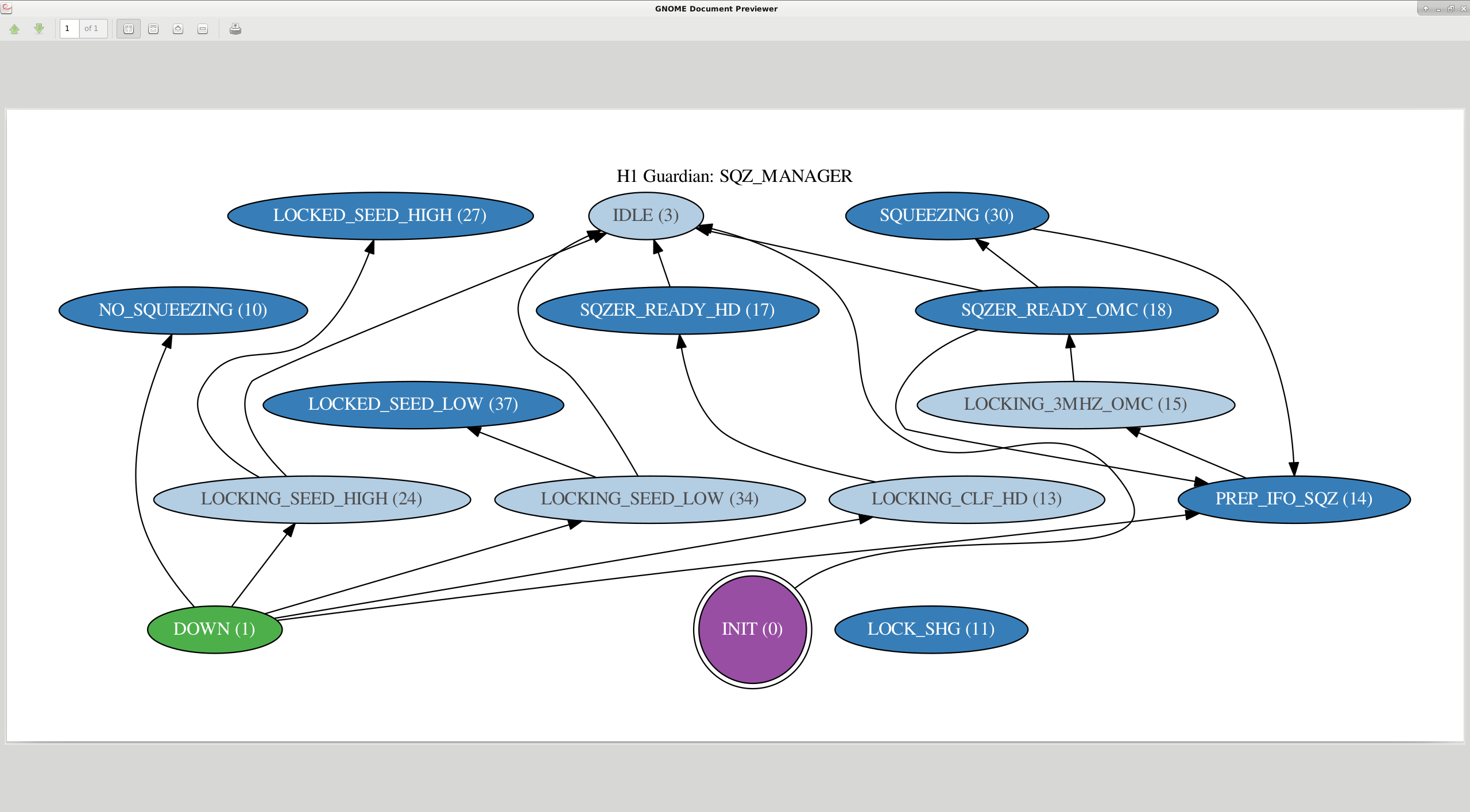
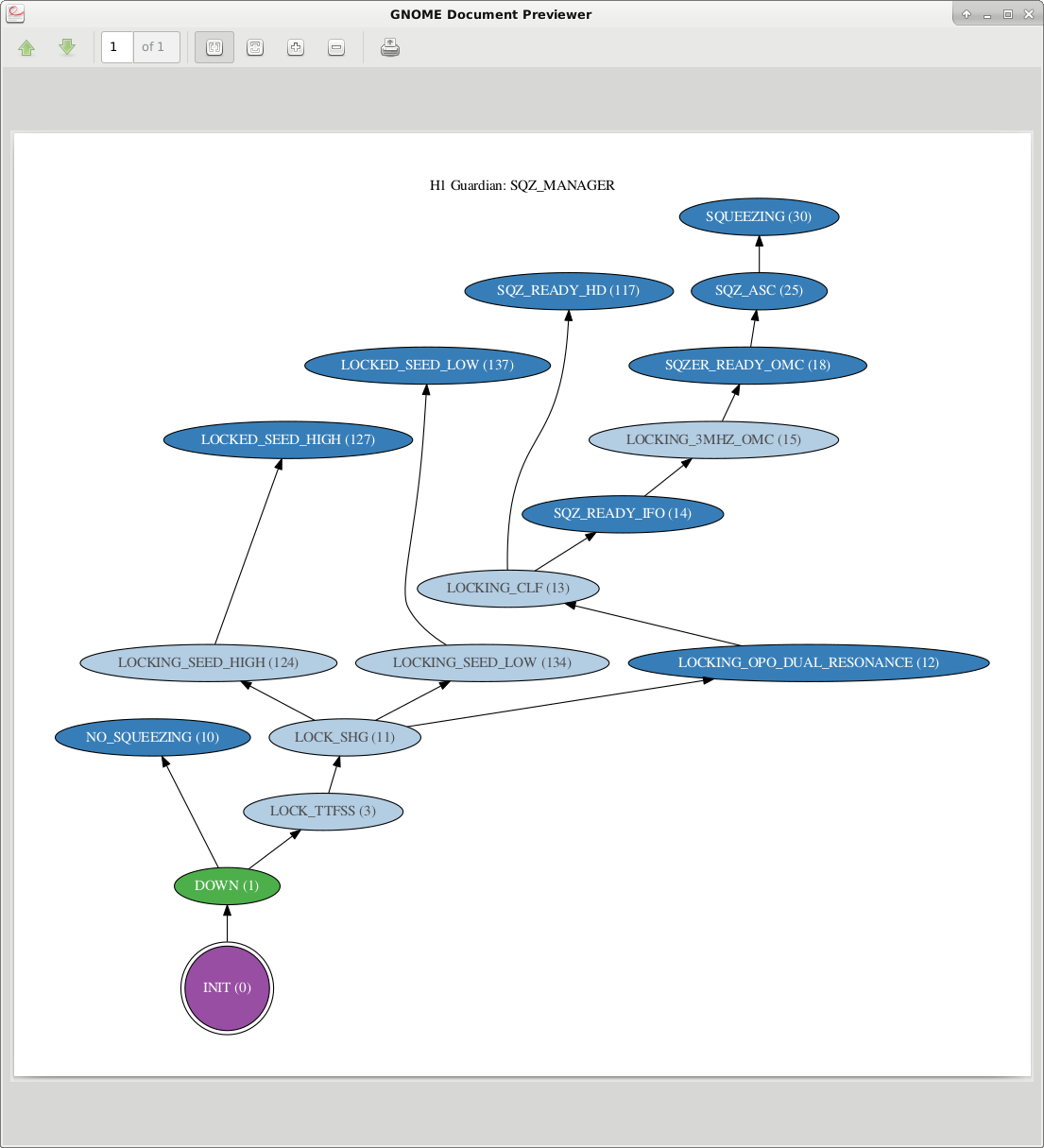
squeezer guardian changes

Earlier the squeezer unlocked and took us out of observing. 

Changes to SQZ_MANAGER:

Images attached to this report
Comments related to this report
daniel.sigg@LIGO.ORG - 19:47, Friday 05 April 2019 (48277)

Loosing that much power through the SHG is a telltale sign that the laser has gone multi-mode. What about the pump power in the OPO? And on the REFL detector? Is it low too? The CLF could also be affected. Not sure, how useful it is to continue running with the squeezer in this configuration.

sheila.dwyer@LIGO.ORG - 20:10, Friday 05 April 2019 (48280)

Daniel-

Agreed that this could be multi moving and we should try to get away from it.  the SHG trans increased again, and the normalized power is only 0.8 at max, so this isn’t as drastic as it sounds.  We are getting around 2dB of squeezing according to the BLRMS.

LHO General (PEM, VE)
gerardo.moreno@LIGO.ORG - posted 17:09, Friday 05 April 2019 (48275)
Y-Mid Activities and Ion Pump Unboxing

Successfully unboxed the large ion pump and moved the wooden crate to LSB receiving.  The crane at Y-Mid was used to unbox the ion pump.

A pallet jack was used to move the wooden crate out of the Y-Mid VEA.

All times are in utc.

The crane at Y-Mid was used continuously starting at 17:55, and stopping at 18:20, time that the crane reached its parking spot.

Door activity at Y-Mid:

- Large outside door:

Rolled open at 21:25 and 21:34

Rolled close at 21:27 and 21:36

- Large inside door:

Rolled open at 21:28

Rolled close at 21:32

H1 General
yannick.lecoeuche@LIGO.ORG - posted 16:23, Friday 05 April 2019 (48273)
Ops EVE Shift Transition

Ops Shift Transition: 04/05/2019, Eve Shift 23:00 – 07:00 (16:00 -00:00) - UTC (PT)

State of H1: Locking

Intent Bit: Commission

Weather: Cloudy and raining. Winds have been going between 10 and 30 mph today, with a brief spike in wind speeds (see 48271).

Primary 0.03 – 0.1Hz: 0.07 um/s

Secondary 0.1 – 0.3Hz: 0.4 um/s

Outgoing Operator: Ed

Quick Summary: Locking IFO after wind spike knocked us out of NLN. Waiting for some squeezer work before going back to NLN.

H1 CAL
sheila.dwyer@LIGO.ORG - posted 18:00, Tuesday 02 April 2019 - last comment - 20:57, Friday 05 April 2019(48178)
changes to pcal correction and delay in sensing measurement processing function, fixed error in DARM filter model

J Kissel, S Dwyer

We spent some time looking at sensing.py today, trying to understand better the systematic error in our sensing function model used for fitting the sensing function measurement.

Pcal Correction:

We also noticed that there is something called OMCDelay (and IOP delay which is insidetotalSensingDigital ) applied in Pcal correction, at first glace it doesn't seem right to apply an OMCDelay here. The default value of both of these delays is 0, and we think that omcDelay was intended to be a delay from sending pCal from the end station to  CalCS model in the corner.  Jeff filed a ticket : 12638  Since both of these are set to 0 delay, they don't impact the systematic error in the sensing or actuation functions. 

DARM excitation delay:

We committed this version of sensing.py at 7121.

DARM filters:

Non-image files attached to this report
Comments related to this report
ling.sun@LIGO.ORG - 10:14, Thursday 04 April 2019 (48240)

Lilli S, Jenne D, Jeff K,

I found the alog documenting when the DARM1 FM3 (resG) filter was turned on (47235). Jenne checked the exact time when the filter was turned on.

2019 Mar 01 23:38:37 UTC -- FM3 was turned on for the first time

2019 Mar 02 03:07-04:02 UTC -- It seems that during this period the filter was turned off again for some calibration testing.

I noticed that there was a measurement template during this time period: /ligo/svncommon/CalSVN/aligocalibration/trunk/Runs/O3/H1/Measurements/FullIFOSensingTFs/2019-03-01_H1_PCAL2DARM_TF_5t1100Hz_8min_AFTER_CHANGE.xml (2019-03-02 03:26:24 UTC)

It is not clear whether the model file modelparams_H1_20190301.py was generated using the measurements when FM3 was on or off. But for all the model files generated after Mar 01, I have added FM3 to the DARM1 filter bank.

sheila.dwyer@LIGO.ORG - 11:17, Friday 05 April 2019 (48265)

We have removed the excitation delay from the DARM EXC/ DARM IN2 measurement processing in sensing.py, because we think this was an error after Jenne looked into it more.  This will make our sensing function fit even worse, like the second attachment above.  

sensing.py is committed at revision 7143

jeffrey.kissel@LIGO.ORG - 20:57, Friday 05 April 2019 (48272)
J. Driggers, J. Kissel, L. Sun

TL;DR -- We also reverted the application of the full pcalCorrection mentioned above today, but now I think there's a bug in the way that the DC gain of the analog anti-aliasing filters (which is 0.99) are applied.

Here's why (as we were reminded by Evan and Shivaraj, but only just finally grokked today):

We take two measurements to obtain a complete measurement of the interferometer's response to differential arm displacement, C_meas,

  DARM_IN1       C_truth      (artifacts in PCAL_RXPD)
 ---------- = ------------- * -----------------------
 PCAL_RXPD    (1 + G)_truth   (artifacts in DARM loop)

  DARM_EXC                     
  --------  = (1 + G)_truth * (artifacts in DARM loop)
  DARM_IN2                  
which, as is indicated above, have some artifacts for which we need to correct.
When we multiply these together, the (artifacts in DARM loop) cancel, leaving

 DARM_IN1      DARM_EXC                            
 --------   *  --------  =  C_truth  *  (artifacts in PCAL_RXPD)
 PCAL_RXPD     DARM_IN2  

Now, we want to isolate C_truth. 

We know that (artifacts in PCAL_RXPD) are what we need to apply to turn the PCAL *channel* back in to DARM displacement,

(artifacts in PCAL_RXPD) = armSign_PCAL * (two poles at 1 Hz) * 1/(PCAL analog AA filter) * 1/(PCAL digital 65k-16k down sampling filter)

                         = armSign_PCAL * ("pcal dewhitening")* 1/(AAanalog_PCAL response * AAanalog_PCAL DC gain) * 1/(AAdigital_PCAL)

where AAanalog_PCAL has been measured to have a DC gain of 0.99 (import later), and AAdigital is a digital filter provided by the RCG with a DC gain of 1.00.

Thus, to get at C_meas alone, we take our two measured transfer functions and divide it by our known "pcalCorrection,"

 DARM_IN1      DARM_EXC                              armSign_PCAL * (two poles at 1 Hz)                       
 --------   *  --------  = C_truth * ----------------------------------------------------------------
 PCAL_RXPD     DARM_IN2             (AAanalog_PCAL response * AAanalog_PCAL DC gain) * AAdigital_PCAL 


           DARM_IN1      DARM_EXC      (AAanalog_PCAL response * AAanalog_PCAL DC gain) * AAdigial_PCAL                        
C_truth =  --------   *  --------  *   ----------------------------------------------------------------
           PCAL_RXPD     DARM_IN2                    armSign_PCAL *  (two poles at 1 Hz)   

We also have a model of this measurement of C_truth, which includes,

C_model =   (Optical Response = optical spring * coupled cavity pole) 
          * (Optical Gain) 
          * (IFO delay = (L/c) * single pole correction) 
          * (Uncompensated high frequency OMC DCPD Trans. Impedance Amp and Analog Whitening Filter Poles) 
          * (OMC DCPD analog AA filter response) * (OMC DCPD analog AA filter gain) 
          * ADC Gain 
          * (OMC DCPD digital 65k-16k down sampling filter)

where the (Optical Response) and (Optical Gain) are the only things we *don't* know or can't measure on the bench. We also *choose* to empirically measure the overall gain, from physical DARM displacement to DARM_IN1 counts, because it's easier to do that than measure the gains of all the electronics (i.e. the trans impedance amp, the whitening chassis, the analog AA, and other things between the "ideal" optical gain and the OMC DCPDs, i.e. between the power coming out of the SRC and the power on the DCPDs), because we can get very precise answer without uncertainty build-up from each term.
So, 
(overall gain) =   (Optical Gain [W/m]) 
                 * (loss between SRM to OMC DCPDs [W/W]) 
                 * (DCPD QE [A/W]) 
                 * (Trans. Impedance Gain [V/A]) 
                 * (Whitening Gain [V/V]) 
                 * (OMC analog AA Gain [V/V]) 
                 * (ADC gain [ct/ V]) 
                 * (whatever digital gains folks have implemented between the ADC channel and DARM_IN1 [ct/ct])

(and, of course, there are two DCPDs, so it's actually the split gain of the two paths recombined digitally in the real-time system, but you get the idea -- we want to fit for the gain of the whole path -- including the OMC DCPD's Analog AA filter gain.)

So we create a multi-parameter MCMC fit on C_truth to obtain the (overall gain) and (overall gain) but that means we must take out everything that we know, i.e.

C_MCMCinput = (Optical Response) * (overall gain) 
            = C_truth / (IFO delay * high freq. DCPD poles * AAanalog_DCPD response * AAdigital_DCPD)

Now here's where things get SNEAKY and CONFUSING.
     (1) We only have one model for the analogAA that we use for both the PCAL and the OMC DCPDs. Thus, analogAA_PCAL = analogAA_DCPD.
     (2) The RCG is doing identically the same thing for the digitalAA. Thus, digitalAA_PCAL = digitalAA_DCPD
That means that technically, we'd have to do *less* to create C_MCMCinput, because the (analogAA_PCAL * digitalAA_PCAL) from pcalCorrection cancel the (analogAA_DPCD * digitalAA_DCPD),

                                                         1
C_MCMCinput = C_truth * -----------------------------------------------------------------------------
                       (IFO delay * high freq. DCPD poles * AAanalog_DCPD response  * AAdigital_DCPD)  


               DARM_IN1      DARM_EXC      (AAanalog_PCAL response * AAanalog_PCAL DC gain) * AAdigial_PCAL                                      1
C_MCMCinput =  --------   *  --------  *   -----------------------------------------------------------------  *  -----------------------------------------------------------------------------
               PCAL_RXPD     DARM_IN2                       armSign_PCAL * (two poles at 1 Hz)                   (IFO delay * high freq. DCPD poles * AAanalog_DCPD response  * AAdigital_DCPD)    


               DARM_IN1      DARM_EXC                  (AAanalog_PCAL response * AAanalog_PCAL DC gain) * AAdigial_PCAL                                                  
C_MCMCinput =  --------   *  --------  *   -------------------------------------------------------------------------------------------------------------
               PCAL_RXPD     DARM_IN2      armSign_PCAL * (two poles at 1 Hz) * IFO delay * high freq. DCPD poles * AAanalog_DCPD response * AAdigital_DCPD  


               DARM_IN1      DARM_EXC                             AAanalog_PCAL DC gain              
C_MCMCinput =  --------   *  --------  *   ------------------------------------------------------------------------
               PCAL_RXPD     DARM_IN2       armSign_PCAL *  (two poles at 1 Hz) * IFO delay * high freq. DCPD poles

So -- you can get away with *only* dividing the measurement by *only* the frequency response (two poles at 1 Hz) and the (high freq. DCPD poles), which is what pyDARM was doing before, we just didn't realize it.. Note, I think pyDARM is still missing the IFO delay, but this works out to be 1 [us], so a small error on top of much bigger impactful things. By applying the full pcalCorrection, we were double counting the analogAA and digitalAA.

Note above, we're left with AAanalog_PCAL DC gain because we've chosen to fold the gain of the OMC DCPD analog AA into the fit of the overall gain.
I would have not have done this sneaky cancellation business, because there's confusion on the way -- BUT the math above gets you the true (overall gain) of the sensing function and the true (optical response).

BUT the DC Gain of the AAanalog_PCAL is not multiplied, it's divided, in pyDARM and I think it results in a missing multiplicative factor of AAanalog_PCAL DC gain = 0.99 in the construction of 1/C_GDS:
     (3) Again, the DC gain of *one* of analogAA models is *divided not multiplied* out of the what is input to the MCMC, and thus
     (4) The "optical gain" max aposteriori (MAP) that is spit out of the MCMC is then a fit to (overall gain) / (analogAA DC gain)^2.
AND
     (5) The user receives information to install 1/MAP into foton for the CAL-CS version of the 1/C correction, so this is wrong by (analogAA DC gain)^2 / (overall gain),
     (6) The sensing function model is reconstructed, it's done with the (overall gain) / (analogAA DC gain)^2 AND *one* of the analog models multiplied in *WITH ITS DC GAIN,* so we get model of C with (overall gain) / (analogAA DC gain), which means comparisons between (the MCMC input / model) are showing (overall gain) / (analogAA DC gain)^3,
     (7) gds corrections for the sensing function are *re*created ( from scratch without the model from (5) ), it's also created with *one* of the analog models *WITH ITS DC GAIN* multiplied, in so GDS corrections to C are 1 / (analogAA DC gain), and thus
     (8) 1/C_GDS = (analogAA DC gain) / C_truth

Let's look at 
    ^/trunk/Common/pyDARM/src/sensing.py   rev 7146

Inside the function "process_sensing_measurements,"

Lines 325-327      PCAL_tf = DARM_IN1 / PCAL_RXPD # essentially, later filtered for coherence, but overwritten with the same name
Lines 334-336       CLG_tf = DARM_EXC / DARM_IN1 # essentially, later filtered for coherence, but overwritten with the same name

Line 361           if modelAndDataPars[n].PCAL_arm == 'Y': sign = -1 # armSign_PCAL from above

                   # Here's where (3) gets applied
                   #                           armSign_PCAL       /        (two poles at 1 Hz)                           /               AAanalog_PCAL DC gain
Line 376           C_meas = PCAL_tf * CLG_tf * sign / signal.freqresp(sensProd.pcaldewhitening, 2.0*np.pi*PCAL_f)[1] / abs(signal.freqresp(sensProd.AAanalog, 2.0*np.pi*0.01)[1])
       
                   #              from above  /           high freq. DCPD poles
Line 380           opticalResponse = C_meas / signal.freqresp(sensProd.uncompensatedOMCDCPD, 2.0*np.pi*PCAL_f)[1]

and opticalResponse (assuming we don't correct for time dependence) is what's input into the MCMC fitting code because (in the same function), the named tuple "results" has its second slot filled with "opticalResponse",
Line 643           thisresult = results(PCAL_f, opticalResponse, unc, err, opticalResponse_mAperpm, err_mAperpm, opticalResponse_ref_tf)
Line 644           allresults.append(thisresult)

and then we zoom down to the function that runs the MCMC fitting, called sensing_MCMC, in which this "opticalResponse" is shoved into the MCMC hammer, 
Line 860           sampler = emcee.EnsembleSampler(nwalkers, ndim, lnprob_antispring, args=(PCAL_f, opticalResponse, err), threads=3)

from which the first of the maximum aposteriori values (MAP) values returned are the "optical gain," which we now know is (overall gain) / (analogAA DC gain)^2.
This MAP values is the "optical gain" that we stick in to any updated parameter file.

For CAL-CS, we just install the inverse of the "optical gain" MAP value, which we now know is (analogAA DC gain)^2 / (overall gain).

Then, this parameter file is used as input *back* in to sensing.py, where C_model is created that is eventually used to create filters for GDS. Here, the analogAA filter is multiplied back in *with its DC Gain*. See
Line 229          # FIXME the variable below is NAMED INCORRECTLY. It's actually C not 1/C. JSK 2019-04-04
Line 237          # gdscorrection = 1/ calcsResid2gdsInvSensOut = 1 / ( 1/C_pyDARM / 1/C_foton ) = (C_pyDARM / C_foton)
Line 238          calcsResid2gdsInvSensOut = signal.freqresp(serielZPK(serielZPK(uncompensatedOMCDCPD, AAanalog), omcDCPDtf), 2.0*np.pi*freq)[1] * AAanalog_delay   # analogAA is multiplied in WITH ITS DC GAIN
Line 239             * delay * singlePoleApproxDelayCorrection 
Line 240             * totalSensingDigital_freqresp 
Line 241             * 1.0/signal.dfreqresp(signal.ZerosPolesGain([],np.zeros(1),1,dt=1.0/2**14), 2.0*np.pi*freq/2**14)[1]  
Line 242             * pars.sensingSign 
Line 243             / IIRwarp_interp   

And this multiplied on to the data stream as 1/calcsResid2gdsInvSensOut (see res_corr_model on line 65 of GDS_FIR_filter_generation.py), so we have
     1                   1                  (analogAA DC gain)^2            1             (analogAA DC gain)
----------- * ------------------------  =   -------------------- *  ------------------ =  ------------------
 MAP value    calcsResid2gdsInvSensOut        (overall gain)        (analogAA DC gain)      (overall gain) 

Which means that at high frequency, GDS, is spitting out 0.99 / C_truth.

Also note that when the pcal correction is created, it's created *WITHOUT THE AA's DC GAIN,
    From above
    pcalCorrection = armSign_PCAL * ("pcal dewhitening")* 1/(AAanalog_PCAL response * AAanalog_PCAL DC gain) * 1/(AAdigital_PCAL)
and yet Line 208 (split for better labeling of parts) of sensing.py is
#                                     ("pcal dewhitening")           /               AAanalog_PCAL response                       /                 AAanalog_PCAL DC gainA           *         Adigital_PCAL        *  delay resolves to 0
pcalCorrection = signal.freqresp(pcaldewhitening, 2.0*np.pi*freq)[1] / (signal.freqresp(AAanalog, 2.0*np.pi*freq)[1]*AAanalog_delay/abs(signal.freqresp(AAanalog, 2.0*np.pi*0.01)[1]) * totalSensingDigital_freqresp * omcDelay_freqresp)


It's quite a kerfuffle. I've opened an FRS ticket for us to solve this issue -- see IIET Ticket 12642.

Displaying reports 41901-41920 of 88750.Go to page Start 2092 2093 2094 2095 2096 2097 2098 2099 2100 End