Displaying reports 41941-41960 of 88742.Go to page Start 2094 2095 2096 2097 2098 2099 2100 2101 2102 End
Reports until 13:18, Thursday 04 April 2019
H1 SEI
jeffrey.bartlett@LIGO.ORG - posted 13:18, Thursday 04 April 2019 (48244)
Weekly HEPI Fluid Level Check (FAMIS #12380)
   Checked CS HEPI fluid level. Level is holding at 6 8/16, has it has been for past few checks. Observed no leaks, drips, odd noises, nor any cause for concern. 

   Closing FAMIS #12380
H1 TCS
jeffrey.bartlett@LIGO.ORG - posted 13:12, Thursday 04 April 2019 (48243)
Weekly TCS Chiller Check (FAMIS #11485)
   Checked both chiller water levels. TCS-X and TCS-Y are both above the full level indicators. No water was added to either chiller. 

   Closing FAMIS #11485
H1 SUS
rahul.kumar@LIGO.ORG - posted 11:19, Thursday 04 April 2019 (48239)
Guardian state during violin mode damping

Sheila, Rahul

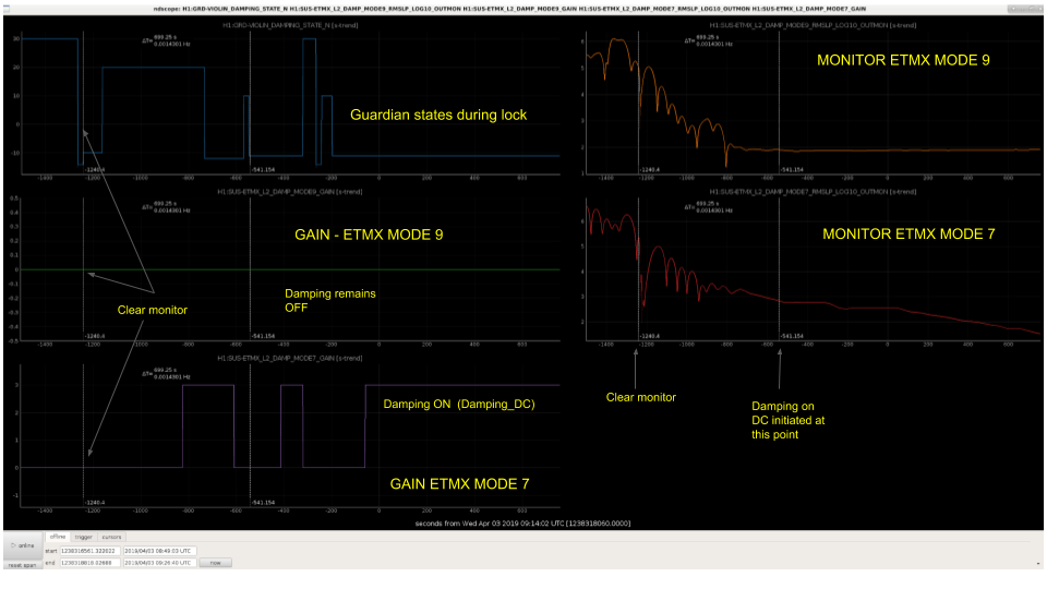
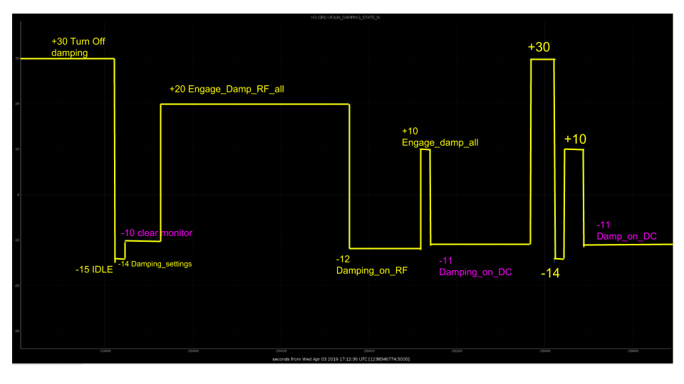
We have been trying to investigate how/why Guardian turns ON/OFF the damping settings for violin modes after lock acquisition. To understand this, first of all we looked at the guardian state (H1:GRD_VIOLIN_DAMPING_STATE_N) on ndscope - right at the beginning of the IFO lock (see figure attached - GRD_Damping.png). During lock loss guardian turns off damping and then moves to IDLE state (during lock). After damping settings state, it clears off the monitor level (to erase the history) and then moves to engage damping (on RF and so an...). Finally it reaches the state called as Damping_on_DC and remains here during the entire stretch of IFO lock.

Next we picked up two modes (ETMX mode 9 and mode 7) as a case study. Usually guardian turns ON the damping for mode 7 and keeps it OFF for mode 9, and we want to know that on what basis guardian makes this decision. In the ndscope we plotted the GAIN and monitor level (rms of excitation) and the guardian state, at the beginning of the lock - see figure attached (ndscope_mode9_mode7.png). In this plot, one can see the time stamp where the guardian clears the monitor level (first vertical broken line) and the point where it turns ON the damping (for mode 7 and keeps it OFF for mode 9 - second vertical broken line). On comparing the monitor levels at this time point (before damping is ON), we can see that mode 9 was at level 2.0  and mode 7 above 3.  Also, the monitor levels for both these modes were either stable or decreasing (and certainly not rising). One can also see that guardian waits for around 700 secs between clear monitor and engage damping. This should give the monitor level enough time to settle down (which is usually excited during lock loss and after).

Next we looked at the python code for violin mode damping and made a few changes. First of all we decreased the DC_noise_floor level to 1.0 (from 3.0) in lscparam file. This should tell the guarding to turn ON the damping during ENGAGE_DAMPING if the the monitor value is greater than 1. Secondly, we made some changes in VIOLIN_DAMPING.py, asking the guardian to look at the absolute value of the GAIN (calc_gain and max_gain) during Damping_on_DC. We also erased the condition (else if) to make the GAIN zero (unless the monitor level is growing) for Damping_on_DC.

The changes made in the python has not been loaded yet as this could lead to losing the ongoing observing mode, which we don't want to. We will wait for an appropriate time during the day to initiate these changes into guardian.

Images attached to this report
H1 SUS (PSL)
edmond.merilh@LIGO.ORG - posted 10:23, Thursday 04 April 2019 (48241)
OpLev Inspection - Weekly FAMIS#11211

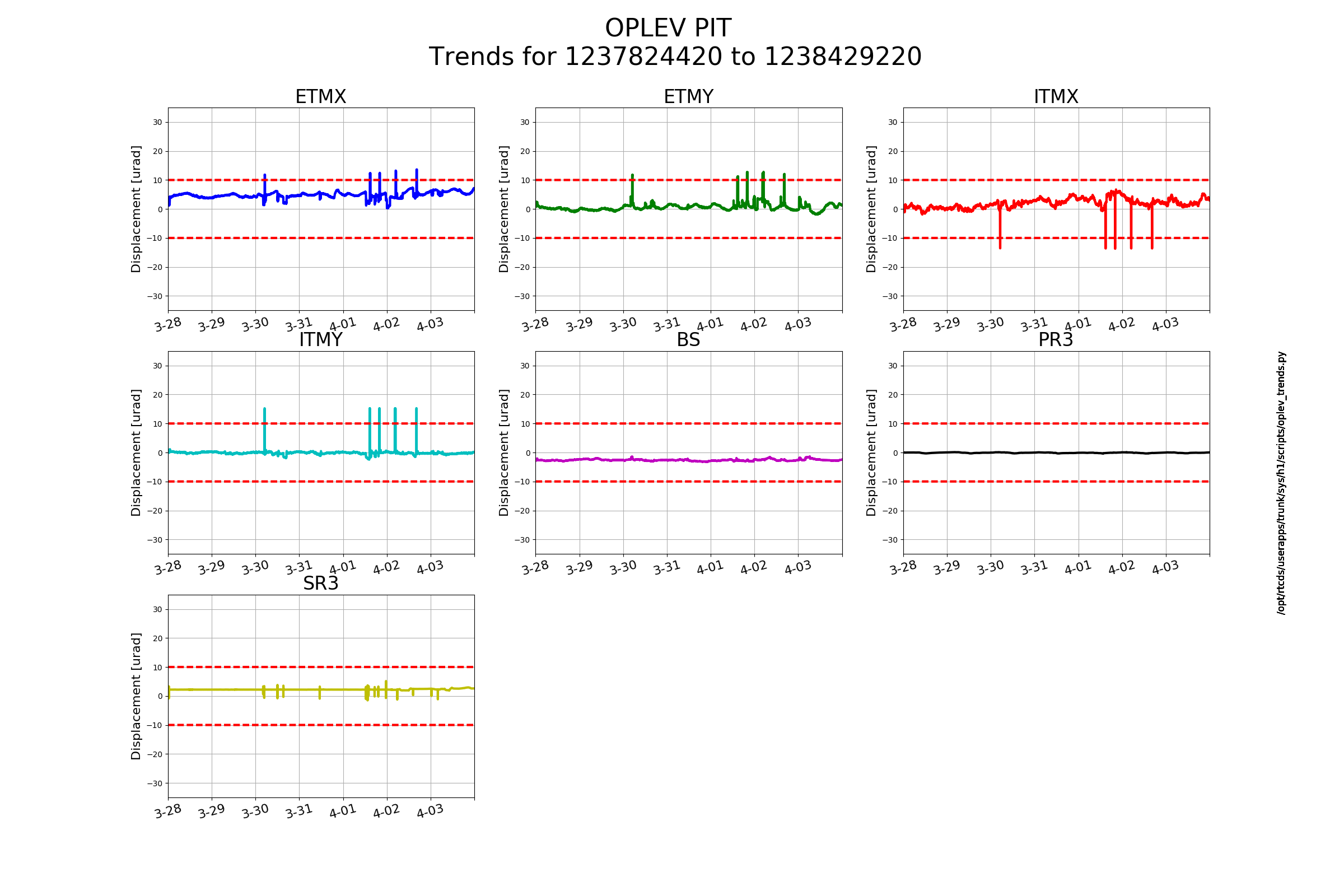
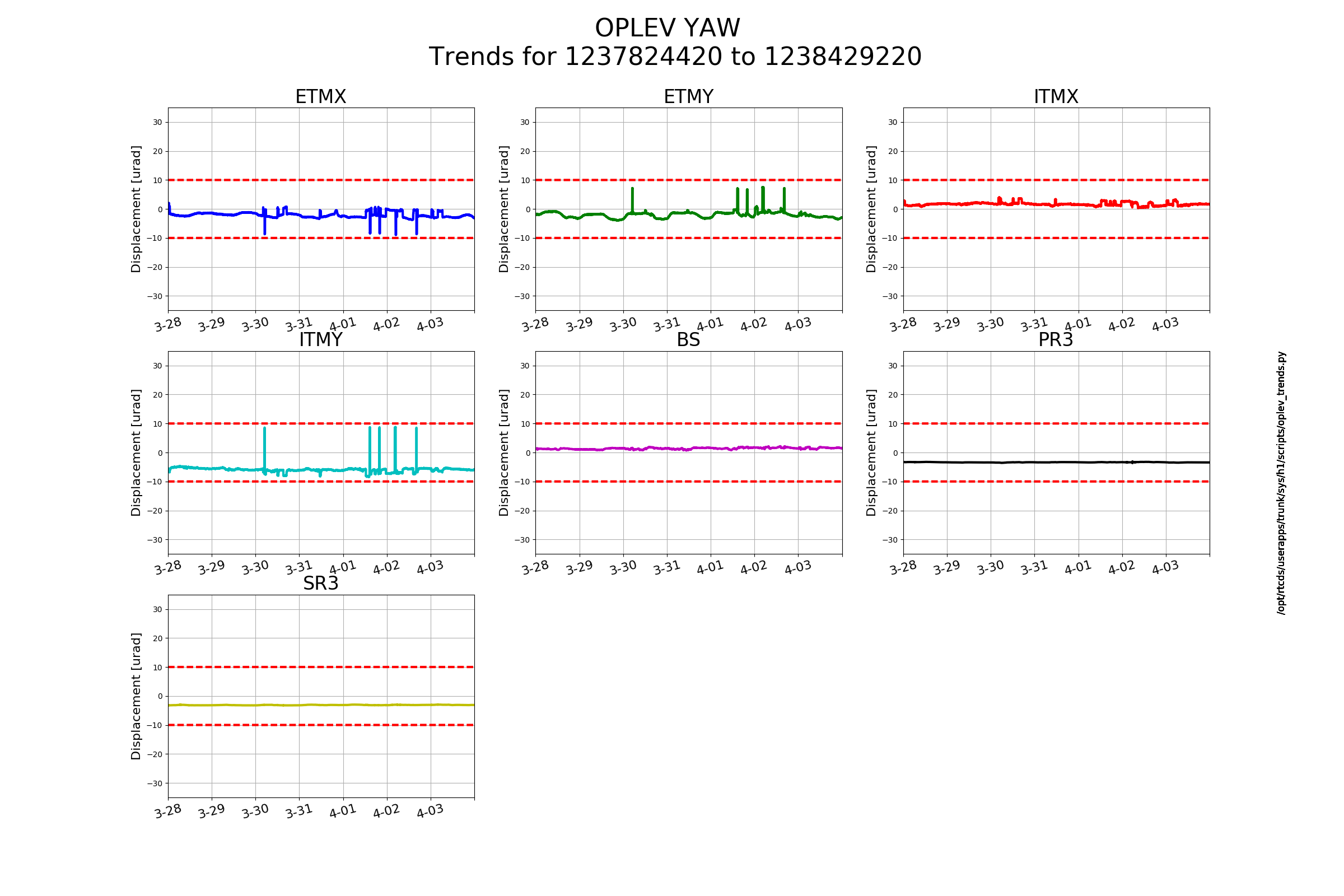
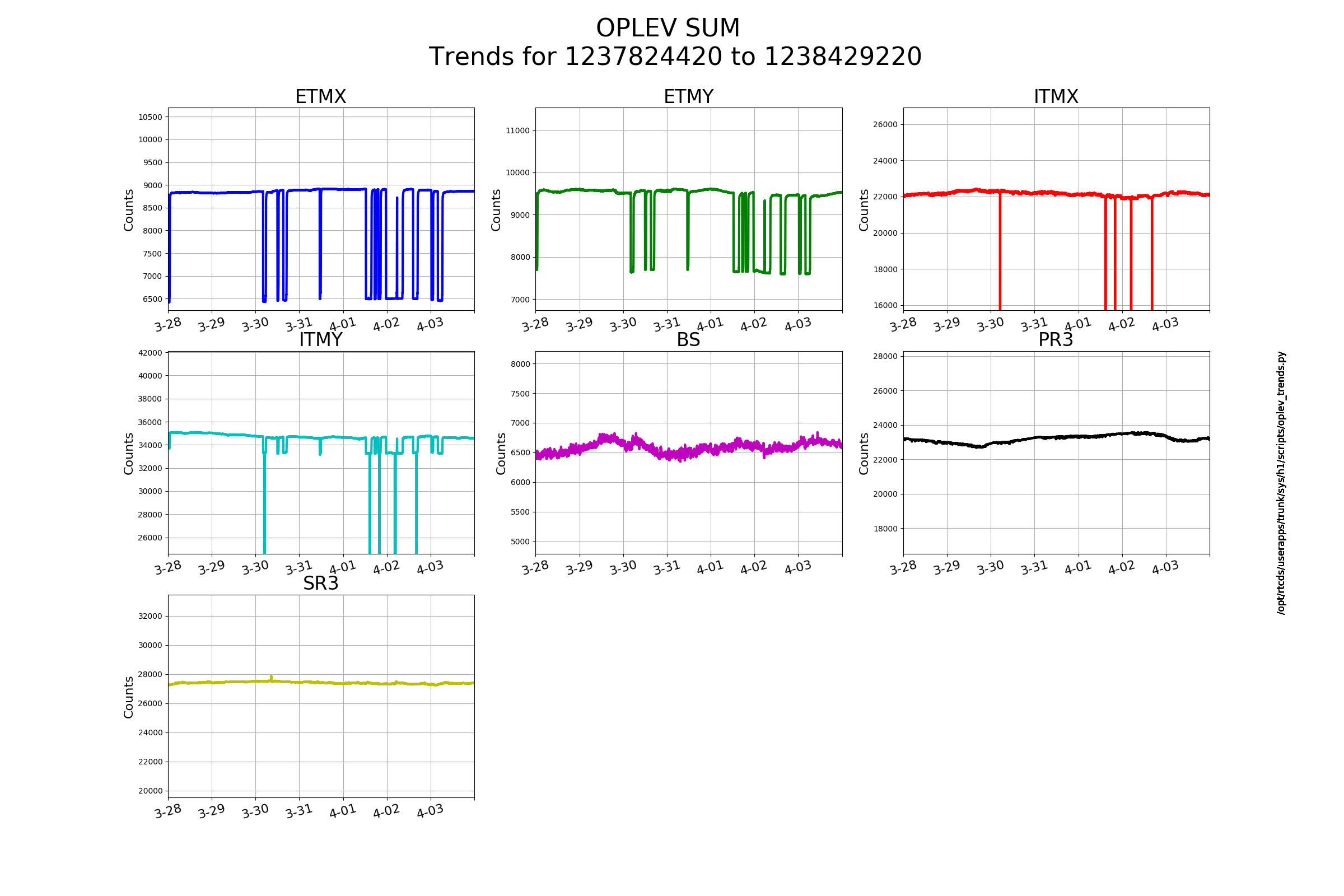
Centering of all OpLevs has been nominally good. That being said any slight misalignments may be being exacerbated by alignment loops/drive during long lock stretches (this particular one is approx 18 hrs). The optimal time to center, after a short discussion with Jenne, would be at DC readout after the soft loops are converged (about 30 or 45 minutes). Otherwise, cold IFO and Aligned optics are the way.

Images attached to this report
H1 PSL
edmond.merilh@LIGO.ORG - posted 10:02, Thursday 04 April 2019 (48238)
PSL Status Report - Weekly FAMIS# 11006

 Laser Status:
    Front End Power is 31.69W (should be around 30 W)
    70W Output Power is 69.09W
    Front End Watch is GREEN
    70W Watch is GREEN

    PMC:
    It has been locked 0 days, 0 hr 46 minutes (should be days/weeks)
    Reflected power = 10.04Watts
    Transmitted power = 54.2Watts
    PowerSum = 64.24Watts.

    FSS:
    It has been locked for 0 days 19 hr and 33 min (should be days/weeks)
    TPD[V] = 4.293V (min 0.9V)

    ISS:
    The diffracted power is around 2.2%
    Last saturation event was 0 days 20 hours and 55 minutes ago (should be days/weeks)


    Possible Issues: N/A

H1 GRD (CDS)
thomas.shaffer@LIGO.ORG - posted 09:58, Thursday 04 April 2019 (48237)
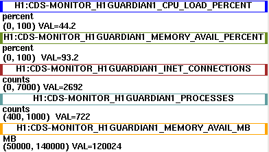
h1guardian1 memory post Tuesday reboot

After the reboot on Tuesday, the h1guardian1 machine has been sitting stably at around 93% memory available. Pre-reboot it was holding around 60%.

(This post is meant to be a note that can be referenced later.)

Images attached to this report
H1 SEI
edmond.merilh@LIGO.ORG - posted 09:44, Thursday 04 April 2019 (48235)
SEI ground seismometer mass position check - Monthly FAMIS #8324

2019-04-04 09:39:26.355722
There are 1 STS proof masses out of range ( > 2.0 [V] )!
STS A DOF X/U = -7.983 [V]

All other proof masses are within range ( < 2.0 [V] ):
STS A DOF Y/V = -0.658 [V]
STS A DOF Z/W = -0.501 [V]
STS B DOF X/U = 0.294 [V]
STS B DOF Y/V = -0.529 [V]
STS B DOF Z/W = -0.334 [V]
STS C DOF X/U = 0.365 [V]
STS C DOF Y/V = 0.244 [V]
STS C DOF Z/W = 0.56 [V]
STS EX DOF X/U = 0.079 [V]
STS EX DOF Y/V = 0.32 [V]2019-04-04 09:39:26.355722
There are 1 STS proof masses out of range ( > 2.0 [V] )!
STS A DOF X/U = -7.983 [V]
STS EX DOF Z/W = 0.227 [V]
STS EY DOF X/U = 0.356 [V]
STS EY DOF Y/V = -0.253 [V]
STS EY DOF Z/W = 0.67 [V]
Assessment complete.


2019-04-04 09:40:52.358417
There are 5 T240 proof masses out of range ( > 0.3 [V] )!
ETMX T240 2 DOF Z/W = -0.316 [V]
ETMY T240 1 DOF Y/V = 0.304 [V]
ITMX T240 1 DOF X/U = -0.611 [V]
ITMX T240 3 DOF X/U = -0.571 [V]
ITMY T240 3 DOF Z/W = -0.74 [V]

All other proof masses are within range ( < 0.3 [V] ):
ETMX T240 1 DOF X/U = -0.109 [V]
ETMX T240 1 DOF Y/V = -0.07 [V]
ETMX T240 1 DOF Z/W = -0.161 [V]
ETMX T240 2 DOF X/U = -0.186 [V]
ETMX T240 2 DOF Y/V = -0.034 [V]
ETMX T240 3 DOF X/U = -0.124 [V]
ETMX T240 3 DOF Y/V = -0.225 [V]
ETMX T240 3 DOF Z/W = -0.076 [V]
ETMY T240 1 DOF X/U = -0.106 [V]
ETMY T240 1 DOF Z/W = -0.066 [V]
ETMY T240 2 DOF X/U = -0.026 [V]
ETMY T240 2 DOF Y/V = -0.09 [V]
ETMY T240 2 DOF Z/W = -0.061 [V]
ETMY T240 3 DOF X/U = -0.083 [V]
ETMY T240 3 DOF Y/V = -0.111 [V]
ETMY T240 3 DOF Z/W = 0.106 [V]
ITMX T240 1 DOF Y/V = 0.076 [V]
ITMX T240 1 DOF Z/W = 0.042 [V]
ITMX T240 2 DOF X/U = 0.092 [V]
ITMX T240 2 DOF Y/V = 0.067 [V]
ITMX T240 2 DOF Z/W = 0.154 [V]
ITMX T240 3 DOF Y/V = 0.053 [V]
ITMX T240 3 DOF Z/W = -0.029 [V]
ITMY T240 1 DOF X/U = 0.102 [V]
ITMY T240 1 DOF Y/V = 0.059 [V]
ITMY T240 1 DOF Z/W = 0.137 [V]
ITMY T240 2 DOF X/U = 0.092 [V]
ITMY T240 2 DOF Y/V = 0.231 [V]
ITMY T240 2 DOF Z/W = 0.118 [V]
ITMY T240 3 DOF X/U = -0.202 [V]
ITMY T240 3 DOF Y/V = 0.12 [V]
BS T240 1 DOF X/U = -0.132 [V]
BS T240 1 DOF Y/V = -0.205 [V]
BS T240 1 DOF Z/W = 0.182 [V]
BS T240 2 DOF X/U = -0.048 [V]
BS T240 2 DOF Y/V = 0.164 [V]
BS T240 2 DOF Z/W = -0.169 [V]
BS T240 3 DOF X/U = -0.019 [V]
BS T240 3 DOF Y/V = -0.288 [V]
BS T240 3 DOF Z/W = -0.29 [V]
Assessment complete.

H1 SEI
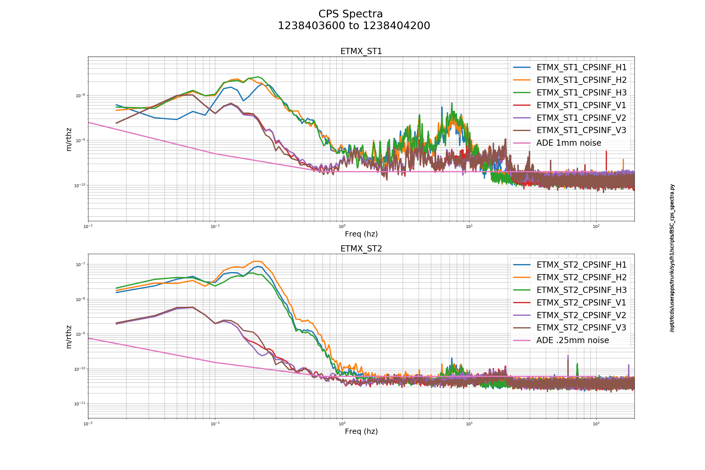
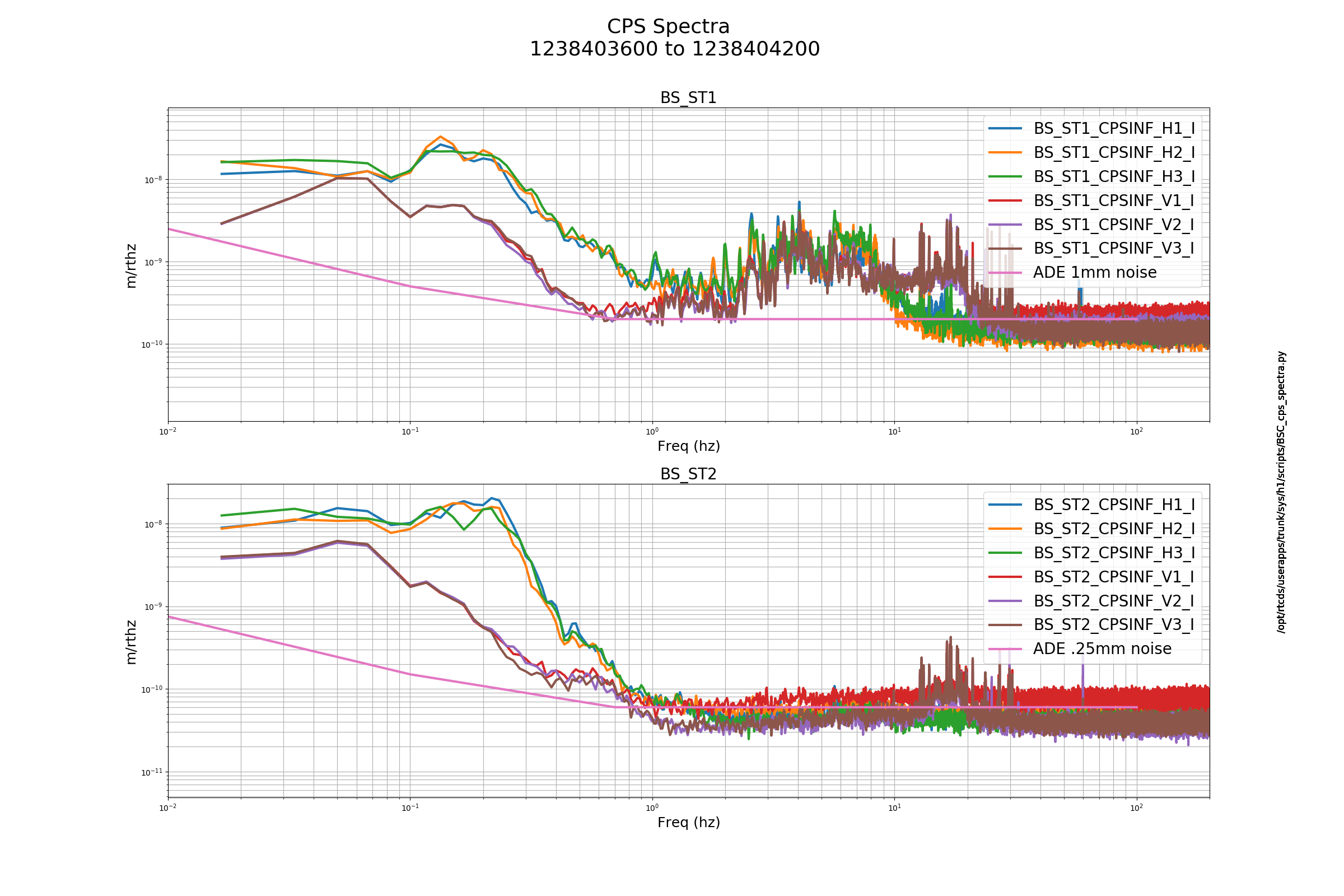
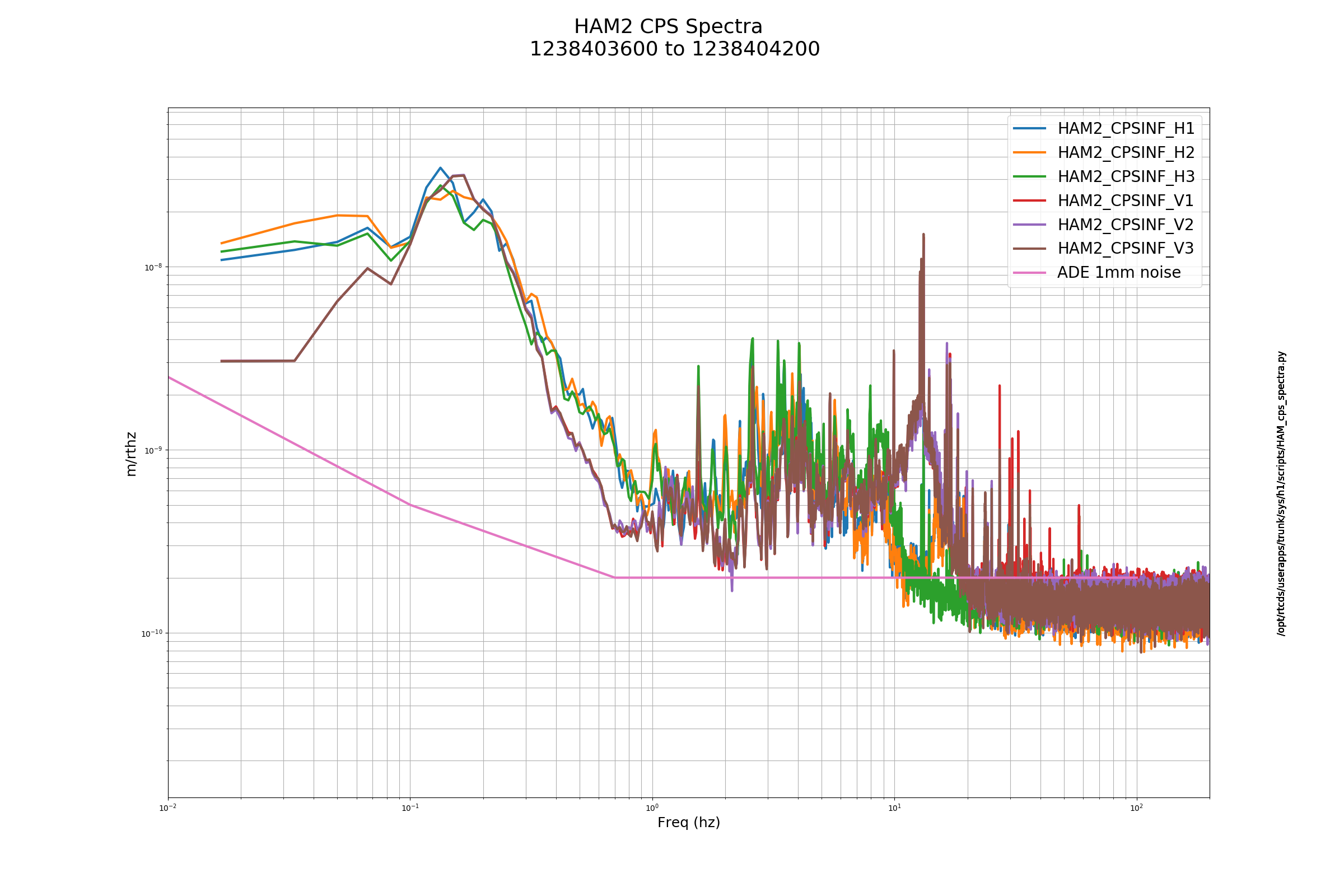
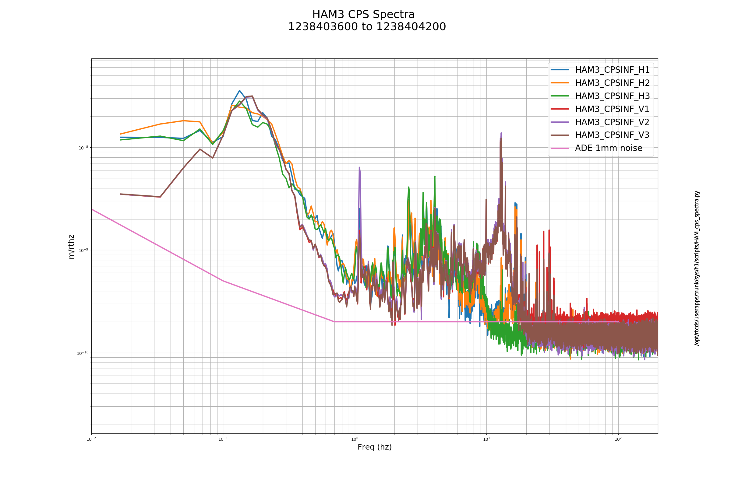
edmond.merilh@LIGO.ORG - posted 09:30, Thursday 04 April 2019 - last comment - 09:34, Thursday 04 April 2019(48233)
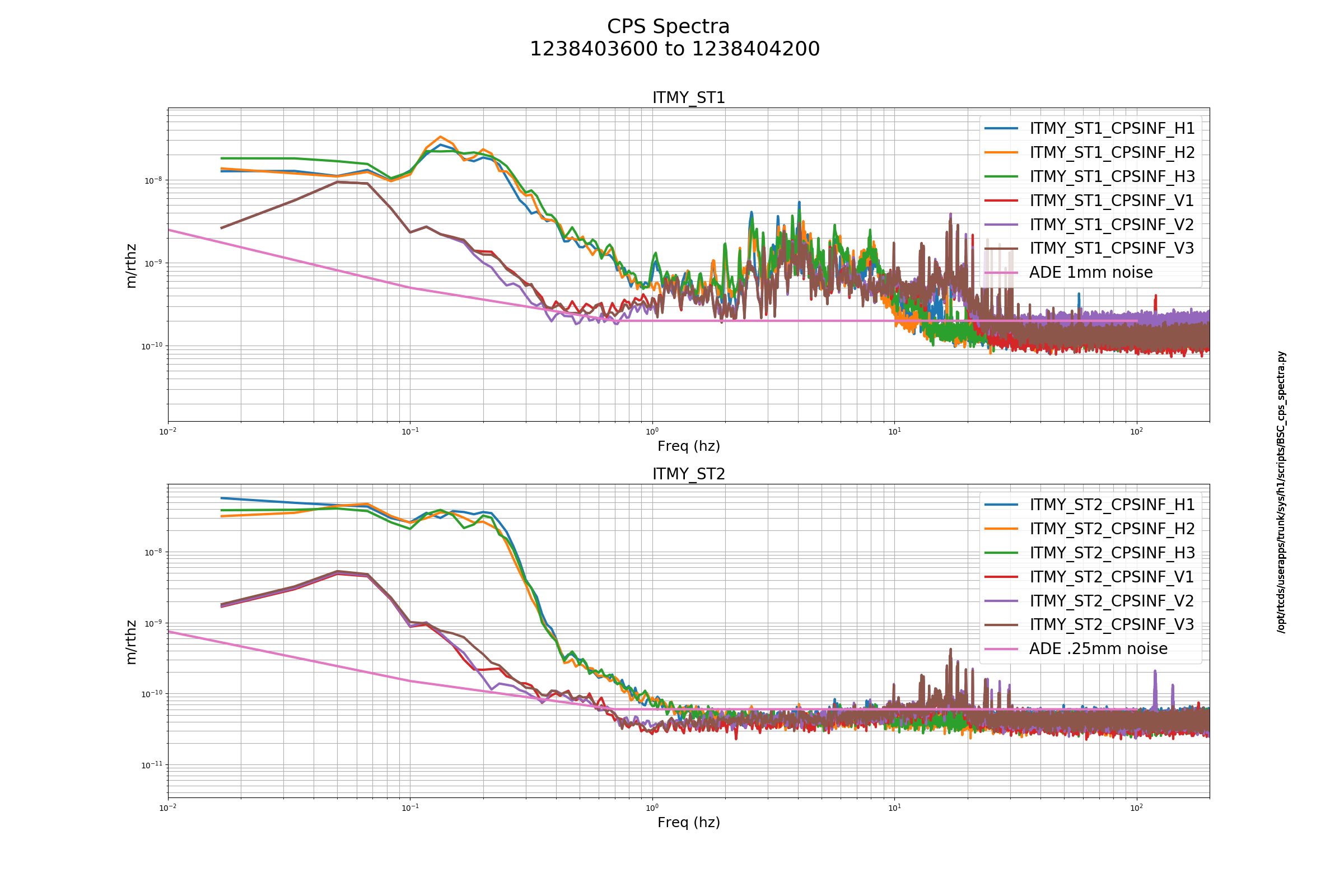
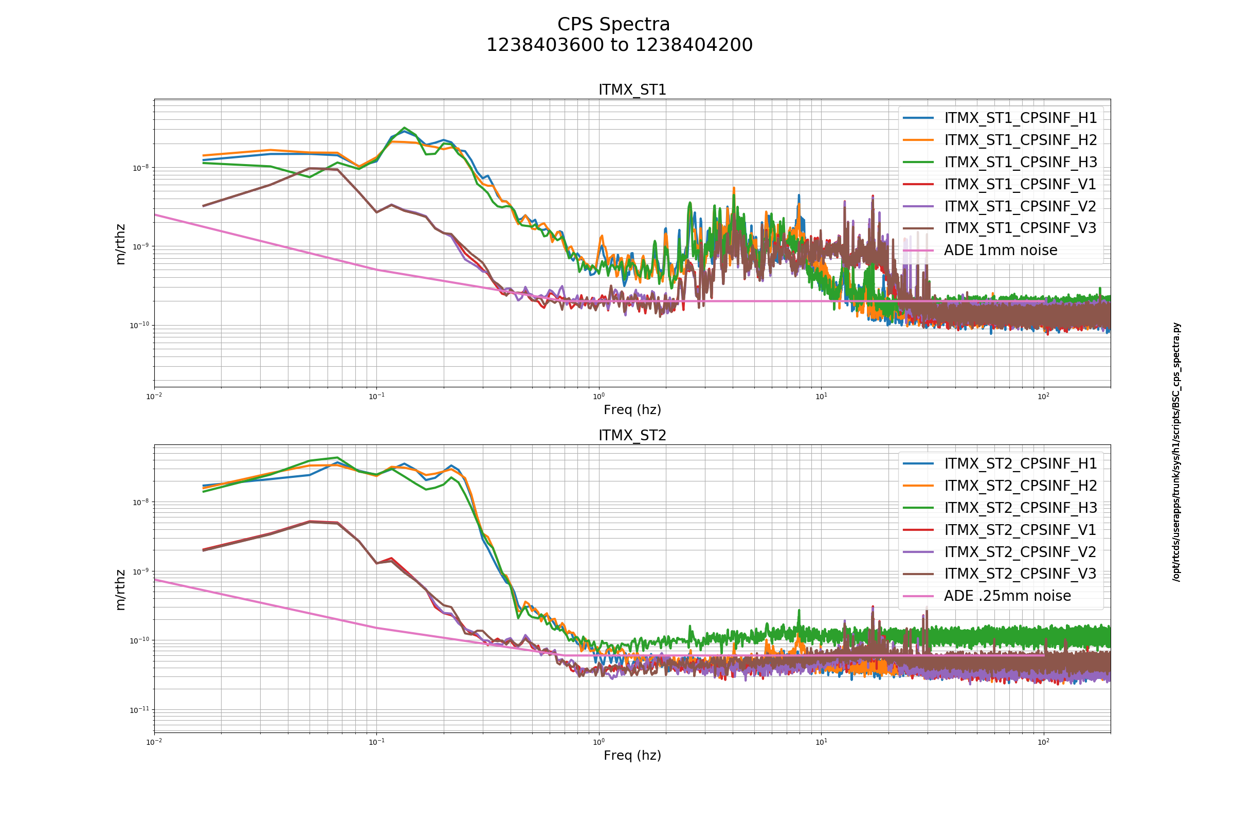
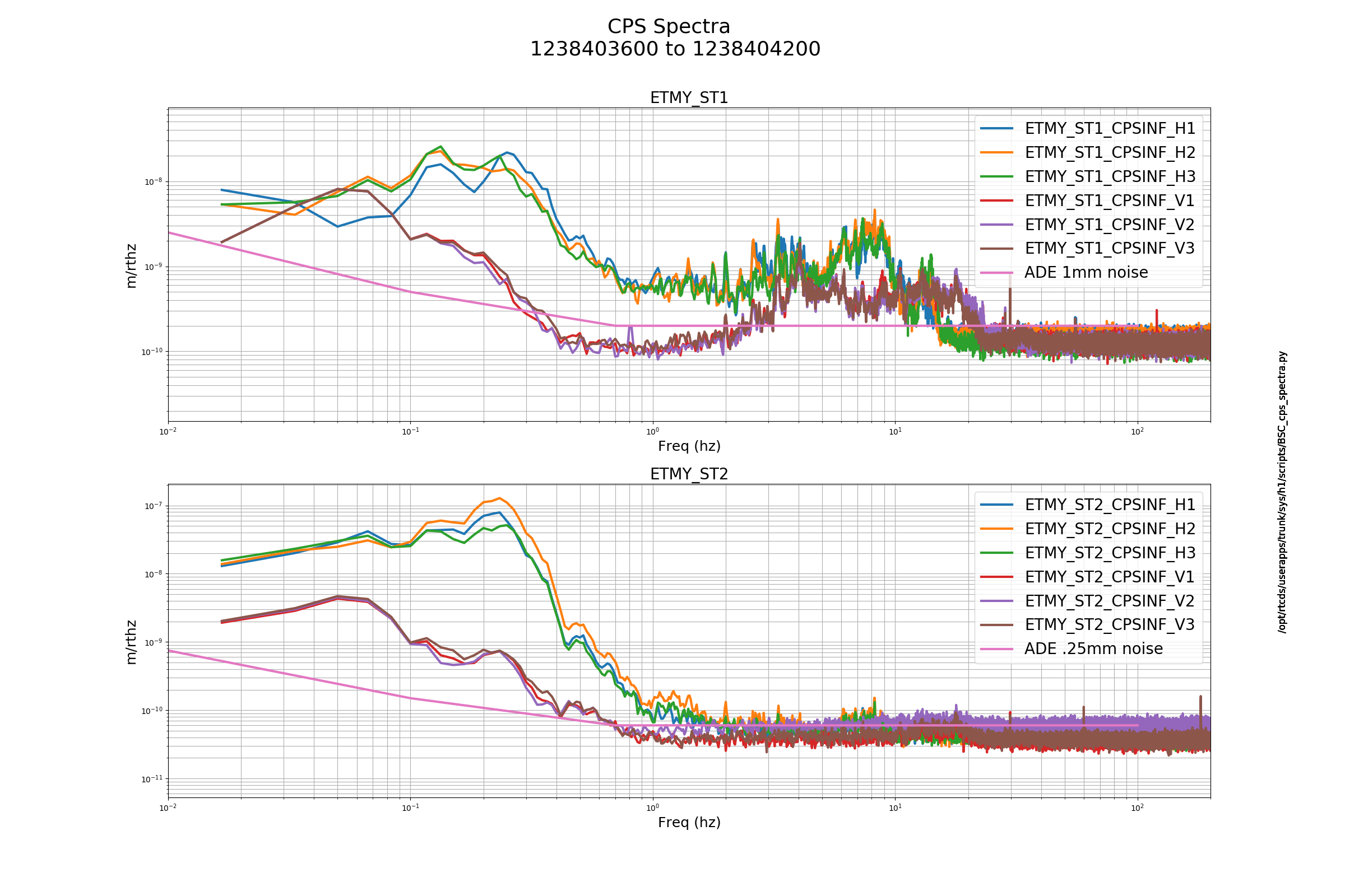
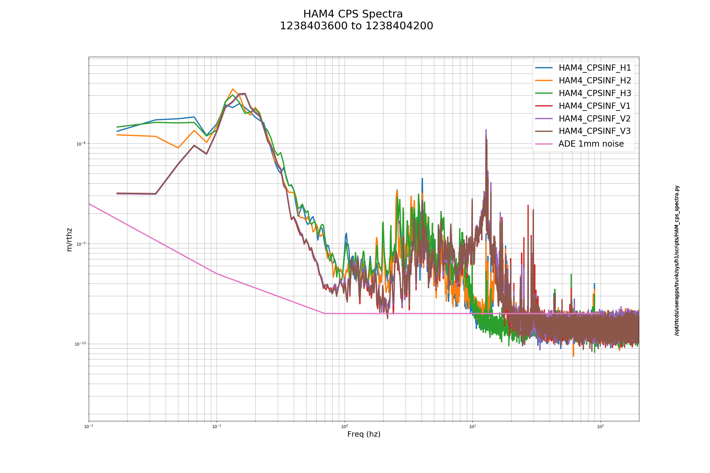
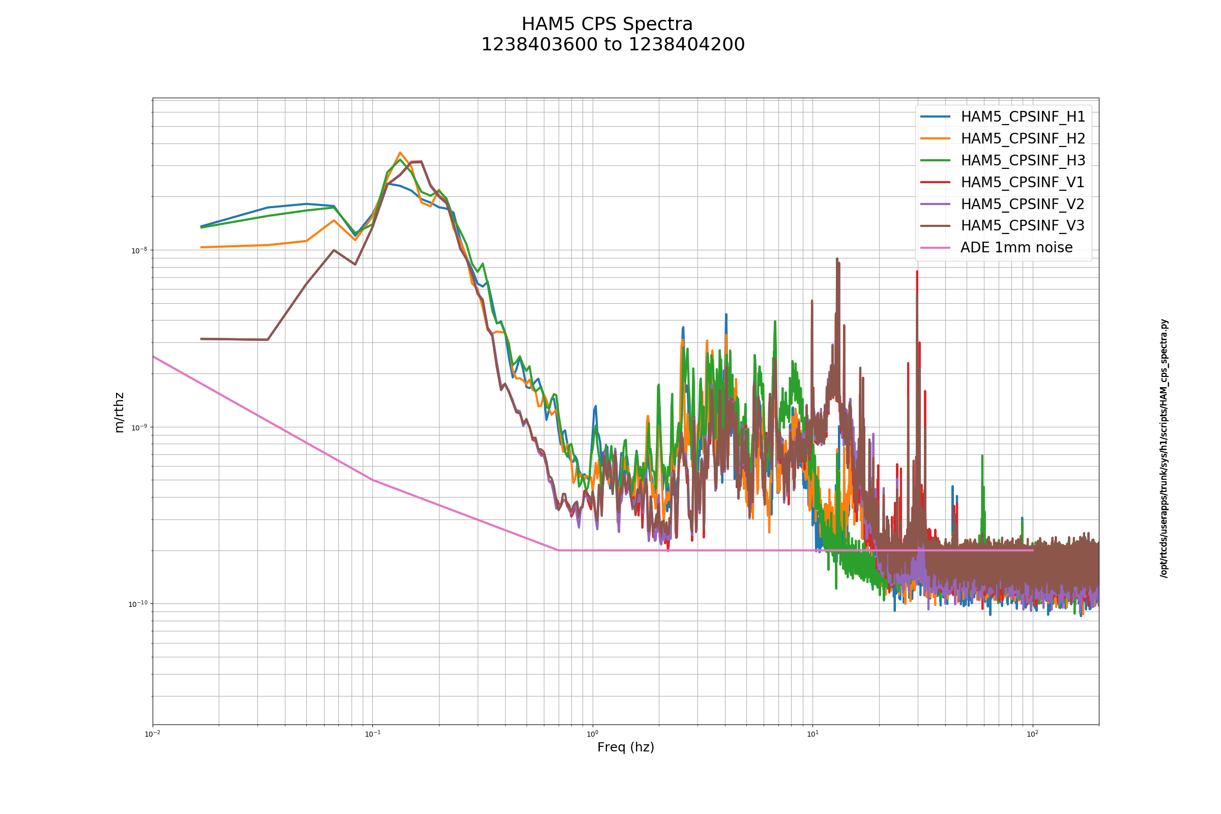
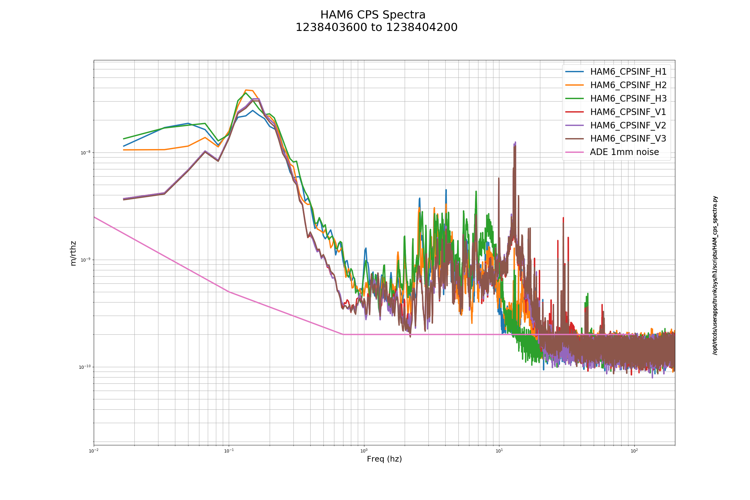
H1 ISI CPS Sensor Noise Spectra Check - Weekly FAMIS #8552

ITMX_ST2_CPSINF_H3 high freq noise is high!


Images attached to this report
Comments related to this report
edmond.merilh@LIGO.ORG - 09:34, Thursday 04 April 2019 (48234)

Posted prematurely: Here's the rest of the story:  All plots look nominal.

Images attached to this comment
H1 AOS
edmond.merilh@LIGO.ORG - posted 08:16, Thursday 04 April 2019 (48232)
Shift Transition - Day

TITLE: 04/04 Day Shift: 15:00-23:00 UTC (08:00-16:00 PST), all times posted in UTC
STATE of H1: Observing at 112Mpc
OUTGOING OPERATOR: Patrick
CURRENT ENVIRONMENT:
    Wind: 4mph Gusts, 3mph 5min avg
    Primary useism: 0.01 μm/s
    Secondary useism: 0.14 μm/s
QUICK SUMMARY:

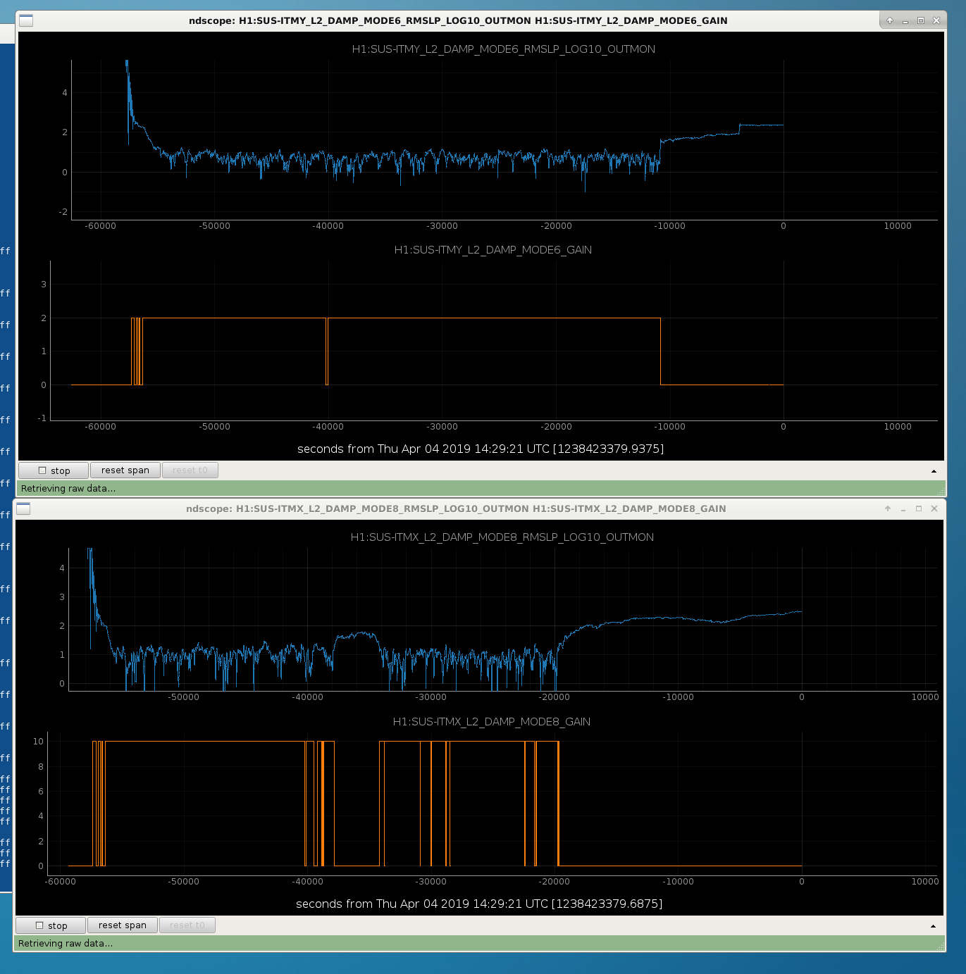
IFO locked and Observing at 110Mpc. 2 violin modes ringing up for the last 3 hours or so.(ITMY Mode 6 and ITMX Mode 8) The concern is not resetting the intent bit if attempts are made to turn these filters on that Guardian has turned off. Sheila looking into it.


LHO General
patrick.thomas@LIGO.ORG - posted 08:00, Thursday 04 April 2019 (48231)
Ops Owl Shift Summary
TITLE: 04/04 Owl Shift: 07:00-15:00 UTC (00:00-08:00 PST), all times posted in UTC
STATE of H1: Observing at 111Mpc
INCOMING OPERATOR: Ed
LOG:

07:01 UTC GRB notification (E328869). Confirmed with LLO.
07:31 UTC Hit diag reset for H1CALCS. Red timing error went away.
11:28 - 11:30 OTC Dropped out of observing by ITMY violin mode 6 gain. Unmonitored and set back to observing.
14:47 UTC Jeff B. to mechanical room
H1 SUS
patrick.thomas@LIGO.ORG - posted 07:29, Thursday 04 April 2019 (48230)
Violin mode damping
The violin mode guardian has turned off the gain for ITMY mode 6 and ITMX mode 8, and this appears to have caused them to start growing. I don't think I can set them back without taking us out of observing, so I am keeping an eye on them for now.
Images attached to this report
H1 General
patrick.thomas@LIGO.ORG - posted 04:33, Thursday 04 April 2019 - last comment - 09:50, Thursday 04 April 2019(48228)
Dropped out of observing by another violin mode gain
ITMY mode 6

11:28 - 11:30 UTC Dropped out of observing

I unmonitored it and went back to observing.

Is something putting these back to monitored?
Images attached to this report
Comments related to this report
thomas.shaffer@LIGO.ORG - 09:50, Thursday 04 April 2019 (48236)SUS

Both Rahul and I have gone through and attempted to unmonitored all of the the gains for modes 1-20 on each quad. Since it isn't easily searched on the SDF screen, it is definitely possible that we missed one or two, but this still seems like too many. I'm hoping that both of us just happen to miss these ones and we are in the clear now.

LHO General
patrick.thomas@LIGO.ORG - posted 03:54, Thursday 04 April 2019 - last comment - 06:21, Thursday 04 April 2019(48226)
Ops Owl Mid Shift Status
Have remained in observing. No major issues to report.
Comments related to this report
patrick.thomas@LIGO.ORG - 03:58, Thursday 04 April 2019 (48227)
H1:PEM-C_SUP_RACK1_TEMPERATURE has been on the edge of the tolerance threshold (< 21).
Non-image files attached to this comment
patrick.thomas@LIGO.ORG - 06:21, Thursday 04 April 2019 (48229)
30 day trend attached.
Non-image files attached to this comment
LHO General
patrick.thomas@LIGO.ORG - posted 00:59, Thursday 04 April 2019 (48225)
Ops Owl Shift Transition
TITLE: 04/04 Owl Shift: 07:00-15:00 UTC (00:00-08:00 PST), all times posted in UTC
STATE of H1: Observing at 107Mpc
OUTGOING OPERATOR: Cheryl
CURRENT ENVIRONMENT:
    Wind: 6mph Gusts, 4mph 5min avg
    Primary useism: 0.02 μm/s
    Secondary useism: 0.18 μm/s 
QUICK SUMMARY:

07:31 UTC Hit diag reset for H1CALCS. Red timing error went away.
H1 CDS
patrick.thomas@LIGO.ORG - posted 00:37, Thursday 04 April 2019 (48224)
Cleared timing error on H1CALCS using diag reset
Attached 8 hour trend of state word. Looks like it went into error around 3:22 UTC on 4/4/2019. Hitting diag reset did not take us out of observing.
Non-image files attached to this report
H1 CAL
sheila.dwyer@LIGO.ORG - posted 18:00, Tuesday 02 April 2019 - last comment - 20:57, Friday 05 April 2019(48178)
changes to pcal correction and delay in sensing measurement processing function, fixed error in DARM filter model

J Kissel, S Dwyer

We spent some time looking at sensing.py today, trying to understand better the systematic error in our sensing function model used for fitting the sensing function measurement.

Pcal Correction:

We also noticed that there is something called OMCDelay (and IOP delay which is insidetotalSensingDigital ) applied in Pcal correction, at first glace it doesn't seem right to apply an OMCDelay here. The default value of both of these delays is 0, and we think that omcDelay was intended to be a delay from sending pCal from the end station to  CalCS model in the corner.  Jeff filed a ticket : 12638  Since both of these are set to 0 delay, they don't impact the systematic error in the sensing or actuation functions. 

DARM excitation delay:

We committed this version of sensing.py at 7121.

DARM filters:

Non-image files attached to this report
Comments related to this report
ling.sun@LIGO.ORG - 10:14, Thursday 04 April 2019 (48240)

Lilli S, Jenne D, Jeff K,

I found the alog documenting when the DARM1 FM3 (resG) filter was turned on (47235). Jenne checked the exact time when the filter was turned on.

2019 Mar 01 23:38:37 UTC -- FM3 was turned on for the first time

2019 Mar 02 03:07-04:02 UTC -- It seems that during this period the filter was turned off again for some calibration testing.

I noticed that there was a measurement template during this time period: /ligo/svncommon/CalSVN/aligocalibration/trunk/Runs/O3/H1/Measurements/FullIFOSensingTFs/2019-03-01_H1_PCAL2DARM_TF_5t1100Hz_8min_AFTER_CHANGE.xml (2019-03-02 03:26:24 UTC)

It is not clear whether the model file modelparams_H1_20190301.py was generated using the measurements when FM3 was on or off. But for all the model files generated after Mar 01, I have added FM3 to the DARM1 filter bank.

sheila.dwyer@LIGO.ORG - 11:17, Friday 05 April 2019 (48265)

We have removed the excitation delay from the DARM EXC/ DARM IN2 measurement processing in sensing.py, because we think this was an error after Jenne looked into it more.  This will make our sensing function fit even worse, like the second attachment above.  

sensing.py is committed at revision 7143

jeffrey.kissel@LIGO.ORG - 20:57, Friday 05 April 2019 (48272)
J. Driggers, J. Kissel, L. Sun

TL;DR -- We also reverted the application of the full pcalCorrection mentioned above today, but now I think there's a bug in the way that the DC gain of the analog anti-aliasing filters (which is 0.99) are applied.

Here's why (as we were reminded by Evan and Shivaraj, but only just finally grokked today):

We take two measurements to obtain a complete measurement of the interferometer's response to differential arm displacement, C_meas,

  DARM_IN1       C_truth      (artifacts in PCAL_RXPD)
 ---------- = ------------- * -----------------------
 PCAL_RXPD    (1 + G)_truth   (artifacts in DARM loop)

  DARM_EXC                     
  --------  = (1 + G)_truth * (artifacts in DARM loop)
  DARM_IN2                  
which, as is indicated above, have some artifacts for which we need to correct.
When we multiply these together, the (artifacts in DARM loop) cancel, leaving

 DARM_IN1      DARM_EXC                            
 --------   *  --------  =  C_truth  *  (artifacts in PCAL_RXPD)
 PCAL_RXPD     DARM_IN2  

Now, we want to isolate C_truth. 

We know that (artifacts in PCAL_RXPD) are what we need to apply to turn the PCAL *channel* back in to DARM displacement,

(artifacts in PCAL_RXPD) = armSign_PCAL * (two poles at 1 Hz) * 1/(PCAL analog AA filter) * 1/(PCAL digital 65k-16k down sampling filter)

                         = armSign_PCAL * ("pcal dewhitening")* 1/(AAanalog_PCAL response * AAanalog_PCAL DC gain) * 1/(AAdigital_PCAL)

where AAanalog_PCAL has been measured to have a DC gain of 0.99 (import later), and AAdigital is a digital filter provided by the RCG with a DC gain of 1.00.

Thus, to get at C_meas alone, we take our two measured transfer functions and divide it by our known "pcalCorrection,"

 DARM_IN1      DARM_EXC                              armSign_PCAL * (two poles at 1 Hz)                       
 --------   *  --------  = C_truth * ----------------------------------------------------------------
 PCAL_RXPD     DARM_IN2             (AAanalog_PCAL response * AAanalog_PCAL DC gain) * AAdigital_PCAL 


           DARM_IN1      DARM_EXC      (AAanalog_PCAL response * AAanalog_PCAL DC gain) * AAdigial_PCAL                        
C_truth =  --------   *  --------  *   ----------------------------------------------------------------
           PCAL_RXPD     DARM_IN2                    armSign_PCAL *  (two poles at 1 Hz)   

We also have a model of this measurement of C_truth, which includes,

C_model =   (Optical Response = optical spring * coupled cavity pole) 
          * (Optical Gain) 
          * (IFO delay = (L/c) * single pole correction) 
          * (Uncompensated high frequency OMC DCPD Trans. Impedance Amp and Analog Whitening Filter Poles) 
          * (OMC DCPD analog AA filter response) * (OMC DCPD analog AA filter gain) 
          * ADC Gain 
          * (OMC DCPD digital 65k-16k down sampling filter)

where the (Optical Response) and (Optical Gain) are the only things we *don't* know or can't measure on the bench. We also *choose* to empirically measure the overall gain, from physical DARM displacement to DARM_IN1 counts, because it's easier to do that than measure the gains of all the electronics (i.e. the trans impedance amp, the whitening chassis, the analog AA, and other things between the "ideal" optical gain and the OMC DCPDs, i.e. between the power coming out of the SRC and the power on the DCPDs), because we can get very precise answer without uncertainty build-up from each term.
So, 
(overall gain) =   (Optical Gain [W/m]) 
                 * (loss between SRM to OMC DCPDs [W/W]) 
                 * (DCPD QE [A/W]) 
                 * (Trans. Impedance Gain [V/A]) 
                 * (Whitening Gain [V/V]) 
                 * (OMC analog AA Gain [V/V]) 
                 * (ADC gain [ct/ V]) 
                 * (whatever digital gains folks have implemented between the ADC channel and DARM_IN1 [ct/ct])

(and, of course, there are two DCPDs, so it's actually the split gain of the two paths recombined digitally in the real-time system, but you get the idea -- we want to fit for the gain of the whole path -- including the OMC DCPD's Analog AA filter gain.)

So we create a multi-parameter MCMC fit on C_truth to obtain the (overall gain) and (overall gain) but that means we must take out everything that we know, i.e.

C_MCMCinput = (Optical Response) * (overall gain) 
            = C_truth / (IFO delay * high freq. DCPD poles * AAanalog_DCPD response * AAdigital_DCPD)

Now here's where things get SNEAKY and CONFUSING.
     (1) We only have one model for the analogAA that we use for both the PCAL and the OMC DCPDs. Thus, analogAA_PCAL = analogAA_DCPD.
     (2) The RCG is doing identically the same thing for the digitalAA. Thus, digitalAA_PCAL = digitalAA_DCPD
That means that technically, we'd have to do *less* to create C_MCMCinput, because the (analogAA_PCAL * digitalAA_PCAL) from pcalCorrection cancel the (analogAA_DPCD * digitalAA_DCPD),

                                                         1
C_MCMCinput = C_truth * -----------------------------------------------------------------------------
                       (IFO delay * high freq. DCPD poles * AAanalog_DCPD response  * AAdigital_DCPD)  


               DARM_IN1      DARM_EXC      (AAanalog_PCAL response * AAanalog_PCAL DC gain) * AAdigial_PCAL                                      1
C_MCMCinput =  --------   *  --------  *   -----------------------------------------------------------------  *  -----------------------------------------------------------------------------
               PCAL_RXPD     DARM_IN2                       armSign_PCAL * (two poles at 1 Hz)                   (IFO delay * high freq. DCPD poles * AAanalog_DCPD response  * AAdigital_DCPD)    


               DARM_IN1      DARM_EXC                  (AAanalog_PCAL response * AAanalog_PCAL DC gain) * AAdigial_PCAL                                                  
C_MCMCinput =  --------   *  --------  *   -------------------------------------------------------------------------------------------------------------
               PCAL_RXPD     DARM_IN2      armSign_PCAL * (two poles at 1 Hz) * IFO delay * high freq. DCPD poles * AAanalog_DCPD response * AAdigital_DCPD  


               DARM_IN1      DARM_EXC                             AAanalog_PCAL DC gain              
C_MCMCinput =  --------   *  --------  *   ------------------------------------------------------------------------
               PCAL_RXPD     DARM_IN2       armSign_PCAL *  (two poles at 1 Hz) * IFO delay * high freq. DCPD poles

So -- you can get away with *only* dividing the measurement by *only* the frequency response (two poles at 1 Hz) and the (high freq. DCPD poles), which is what pyDARM was doing before, we just didn't realize it.. Note, I think pyDARM is still missing the IFO delay, but this works out to be 1 [us], so a small error on top of much bigger impactful things. By applying the full pcalCorrection, we were double counting the analogAA and digitalAA.

Note above, we're left with AAanalog_PCAL DC gain because we've chosen to fold the gain of the OMC DCPD analog AA into the fit of the overall gain.
I would have not have done this sneaky cancellation business, because there's confusion on the way -- BUT the math above gets you the true (overall gain) of the sensing function and the true (optical response).

BUT the DC Gain of the AAanalog_PCAL is not multiplied, it's divided, in pyDARM and I think it results in a missing multiplicative factor of AAanalog_PCAL DC gain = 0.99 in the construction of 1/C_GDS:
     (3) Again, the DC gain of *one* of analogAA models is *divided not multiplied* out of the what is input to the MCMC, and thus
     (4) The "optical gain" max aposteriori (MAP) that is spit out of the MCMC is then a fit to (overall gain) / (analogAA DC gain)^2.
AND
     (5) The user receives information to install 1/MAP into foton for the CAL-CS version of the 1/C correction, so this is wrong by (analogAA DC gain)^2 / (overall gain),
     (6) The sensing function model is reconstructed, it's done with the (overall gain) / (analogAA DC gain)^2 AND *one* of the analog models multiplied in *WITH ITS DC GAIN,* so we get model of C with (overall gain) / (analogAA DC gain), which means comparisons between (the MCMC input / model) are showing (overall gain) / (analogAA DC gain)^3,
     (7) gds corrections for the sensing function are *re*created ( from scratch without the model from (5) ), it's also created with *one* of the analog models *WITH ITS DC GAIN* multiplied, in so GDS corrections to C are 1 / (analogAA DC gain), and thus
     (8) 1/C_GDS = (analogAA DC gain) / C_truth

Let's look at 
    ^/trunk/Common/pyDARM/src/sensing.py   rev 7146

Inside the function "process_sensing_measurements,"

Lines 325-327      PCAL_tf = DARM_IN1 / PCAL_RXPD # essentially, later filtered for coherence, but overwritten with the same name
Lines 334-336       CLG_tf = DARM_EXC / DARM_IN1 # essentially, later filtered for coherence, but overwritten with the same name

Line 361           if modelAndDataPars[n].PCAL_arm == 'Y': sign = -1 # armSign_PCAL from above

                   # Here's where (3) gets applied
                   #                           armSign_PCAL       /        (two poles at 1 Hz)                           /               AAanalog_PCAL DC gain
Line 376           C_meas = PCAL_tf * CLG_tf * sign / signal.freqresp(sensProd.pcaldewhitening, 2.0*np.pi*PCAL_f)[1] / abs(signal.freqresp(sensProd.AAanalog, 2.0*np.pi*0.01)[1])
       
                   #              from above  /           high freq. DCPD poles
Line 380           opticalResponse = C_meas / signal.freqresp(sensProd.uncompensatedOMCDCPD, 2.0*np.pi*PCAL_f)[1]

and opticalResponse (assuming we don't correct for time dependence) is what's input into the MCMC fitting code because (in the same function), the named tuple "results" has its second slot filled with "opticalResponse",
Line 643           thisresult = results(PCAL_f, opticalResponse, unc, err, opticalResponse_mAperpm, err_mAperpm, opticalResponse_ref_tf)
Line 644           allresults.append(thisresult)

and then we zoom down to the function that runs the MCMC fitting, called sensing_MCMC, in which this "opticalResponse" is shoved into the MCMC hammer, 
Line 860           sampler = emcee.EnsembleSampler(nwalkers, ndim, lnprob_antispring, args=(PCAL_f, opticalResponse, err), threads=3)

from which the first of the maximum aposteriori values (MAP) values returned are the "optical gain," which we now know is (overall gain) / (analogAA DC gain)^2.
This MAP values is the "optical gain" that we stick in to any updated parameter file.

For CAL-CS, we just install the inverse of the "optical gain" MAP value, which we now know is (analogAA DC gain)^2 / (overall gain).

Then, this parameter file is used as input *back* in to sensing.py, where C_model is created that is eventually used to create filters for GDS. Here, the analogAA filter is multiplied back in *with its DC Gain*. See
Line 229          # FIXME the variable below is NAMED INCORRECTLY. It's actually C not 1/C. JSK 2019-04-04
Line 237          # gdscorrection = 1/ calcsResid2gdsInvSensOut = 1 / ( 1/C_pyDARM / 1/C_foton ) = (C_pyDARM / C_foton)
Line 238          calcsResid2gdsInvSensOut = signal.freqresp(serielZPK(serielZPK(uncompensatedOMCDCPD, AAanalog), omcDCPDtf), 2.0*np.pi*freq)[1] * AAanalog_delay   # analogAA is multiplied in WITH ITS DC GAIN
Line 239             * delay * singlePoleApproxDelayCorrection 
Line 240             * totalSensingDigital_freqresp 
Line 241             * 1.0/signal.dfreqresp(signal.ZerosPolesGain([],np.zeros(1),1,dt=1.0/2**14), 2.0*np.pi*freq/2**14)[1]  
Line 242             * pars.sensingSign 
Line 243             / IIRwarp_interp   

And this multiplied on to the data stream as 1/calcsResid2gdsInvSensOut (see res_corr_model on line 65 of GDS_FIR_filter_generation.py), so we have
     1                   1                  (analogAA DC gain)^2            1             (analogAA DC gain)
----------- * ------------------------  =   -------------------- *  ------------------ =  ------------------
 MAP value    calcsResid2gdsInvSensOut        (overall gain)        (analogAA DC gain)      (overall gain) 

Which means that at high frequency, GDS, is spitting out 0.99 / C_truth.

Also note that when the pcal correction is created, it's created *WITHOUT THE AA's DC GAIN,
    From above
    pcalCorrection = armSign_PCAL * ("pcal dewhitening")* 1/(AAanalog_PCAL response * AAanalog_PCAL DC gain) * 1/(AAdigital_PCAL)
and yet Line 208 (split for better labeling of parts) of sensing.py is
#                                     ("pcal dewhitening")           /               AAanalog_PCAL response                       /                 AAanalog_PCAL DC gainA           *         Adigital_PCAL        *  delay resolves to 0
pcalCorrection = signal.freqresp(pcaldewhitening, 2.0*np.pi*freq)[1] / (signal.freqresp(AAanalog, 2.0*np.pi*freq)[1]*AAanalog_delay/abs(signal.freqresp(AAanalog, 2.0*np.pi*0.01)[1]) * totalSensingDigital_freqresp * omcDelay_freqresp)


It's quite a kerfuffle. I've opened an FRS ticket for us to solve this issue -- see IIET Ticket 12642.

Displaying reports 41941-41960 of 88742.Go to page Start 2094 2095 2096 2097 2098 2099 2100 2101 2102 End