IM4 (and IM4 baffle) beam position
This is a belated alog from Tuesday.
Starting point: Same alignment for MC123, IM123 as last Friday, i.e. the IM4 baffle NOT centered nor unclipped.
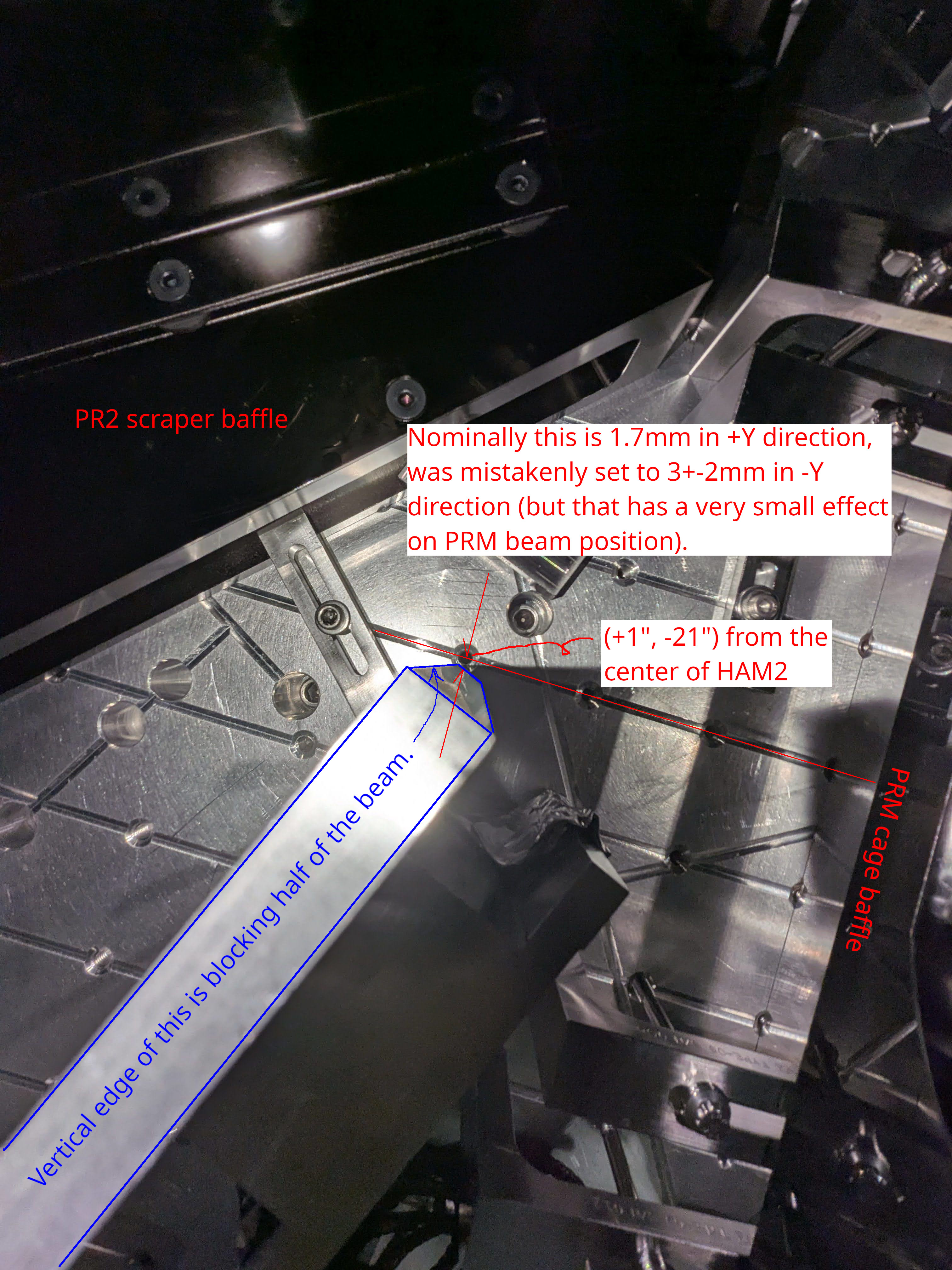
Without touching IMC and IM1/2/3, we rotated IM4 to steer the beam close enough to the nominal beam position in front of PR2, and measured the beam position horizontally and vertically relative to the known screw hole in front of PR2 and PRM.
The distance between IM4-PRM beam line as of now relative to the nominal PRM-PR2 center line was calculated to be 3.9+-1.1mm in -Y direction and too low by 2.9+-1.1mm. See measurement_cartoon.jpg for the horizontal position case. Height is derived in the same way. Since the beam position in front of PR2 is not grossly off, and since IM4 is much, much closer to PRM than PR2, you can use these numbers as the spot position on PRM, too.
From IM4baffle_20260526.jpg, centering the beam on PRM will correct the height on IM4 baffle (HA12). Horizontally it will within a couple mm or so from the center.
What we should do
As we're running out of time, give up the idea to understand what happened to the alignment during the vent before closing HAM2. We should recenter things whenever possible (but only when the IFO REFL path and POP sled path are not disturbed to the point we clip or lose the beam).
For IMC,
- Since MC3 beam spot is great but MC2 spot is off by 3.6mm in -Y direction, center the beam spot on MC2 (i.e. move it by 3.6mm in +Y direction using JM3) but don't move the beam spot on MC3.
- This is a scaled-down version of the yellow-orange trace in the plot ("Rotation around MC3" case in cartoon_IMC_alignment_to_unclip.png) from alog 90295, causing about 220urad angle change for the beam coming out of MC3 and will shift the beam by 3*3.6/11~1mm on PRM in positive Y direction.
- This is done by:
- Measure the beam spot of MC1 transmission in front of MC2. Rotate JM3 until the beam comes to the expected position.
- Measure the beam spot on MC2 reflection in front of MC3. Rotate MC2 until the beam comes to the expected position.
- Use MC3 to roughly make the 1 round-trip beam (MC3 reflection reflected by MC1) go on top of the input beam near MC1.
- Use MC1 to roughly make the 1-round trip beam go on top of the input beam near MC2.
- Only use MC3 and MC1 to refine.
For IMs,
following is the table of slider offsets as of now.
| IM1 | IM2 | IM3 | IM4 | |
| PIT | 517 | 810 | -614 | 531 |
| YAW | -387 | -88 | 385 | 64 |
Even though the physical PIT angle of the optics relative to the local vertical axis is arbitrary, it seems that IM1 is bringing the beam down on IM2, IM2 is bringing down the beam further on IM3, and IM3 is bringing up the beam on IM4 and PRM. But IM2 is twise as efficient as IM3 for changing the beam position on PRM. Besides, the beam is already coming down from MC2 to MC3 (about 10mm height difference over 16m, or about 220urad) and I don't know if it makes sense to use IM2 to bring the beam further down. It's worth redistributing PIT as well as YAW offsets to relieve big offsets.
However, note that ultimately IM1-IM2 line defines the IFO REFL path when PRM retroreflects. (Even if you rotate IM2, as far as IM1-IM2 line doesn't change the IFO refl beam won't move.) I won't touch IM1 as moving the beam on e.g. IM2 even just a few mm using IM1 (i.e. a few mm over ~1.8m leverarm) will result in a much bigger change for REFL path in HAM1, potentially risking yet another clipping or maybe the loss of the REFL beam. IMC alignment noted above will change the IM1-IM2 line, but that's basically the angle change of ~3.6mm/16m (i.e. an order of magnitude smaller than when moving IM1 to steer the beam on IM2 in a meangful amplitude). That's small enough it's hard to imagine that the beam will be clipped by IFO refl baffle nor the downstream optics.
So,
- Don't touch IM1 as the lever arm for IM1 to anything in HAM2 is much shorter than MC2-MC3 length and it will affect the IFO refl path in a meaningful manner. Don't try to center the beam on IFI input baffle using IM1, it's not too bad (see this picture from alog 90295). It's not ideal but we can live with that, IFI aperture is 20mm and the IFI input baffle aperture is 16mm.
- Before starting to move IM2/3, make sure that PRM is retroreflecting. Adjust PRM if not.
- Look at IFO refl on IFO refl baffle. If it's clipped, something is wrong, come out of the chamber and talk to others before proceeding.
- If IFO refl baffle looks fine, confirm that the flashing is visible in HAM1 LSC and ISC sensors.
- Look at the beam spot on IFI output baffle, if possible at all. Depending on how it looks, we could try something like below.
|
PIT |
IM2 | IM3 | IM4 | PRM |
| IM2 (810 -> 310, negative 500urad) | 0 | 1.2 | +2.8 | +3.5mm |
| IM3 (-614.7 -> -434.7, positive 180urad) | -0.4 | -0.6mm | ||
| Total change | 1.2 | 2.4 | 2.9mm (higher) | |
| Position as of now | -2.9mm (too low) |
| YAW | IM2 | IM3 | IM4 | PRM |
| From MC2 beam spot change |
0.4mm (-X) |
0.6mm (-X) | 1mm (-X) | 1.2mm (+Y) |
| IM2 (-88 -> 112urad, positive 200urad change) | 0.5mm (-X) | 1.1mm (-X) | 1.4mm (+Y) | |
| IM3 (385urad -> 0, negative 385 urad change) | 0.9mm (-X) | 1.3mm (+Y) | ||
| Total change | 0.4mm (-X) | 1.1mm (-X) | 3mm (-X) | 3.9mm (+Y) |
| Position as of now | 3.9mm (-Y) |
Of course this is assuming that the slider calibration is correct, so take this as a qualitative reference to get the sense of sign of angle changes. Anyway, when this is done, the DAC counts for IM2 and IM3 will be smaller while the beam height on PR2 will be fine.
| IM1 (no touch) | IM2 | IM3 | IM4 | |
| PIT | 517 | 810-> 310 | -614-> -434.7 | 531-> ? |
| YAW | -387 | -88-> 112 | 385-> 0 | 64-> ? |
After doing the above,
If centering HA12 (IM4) baffle is important, relocate HA12. I'll ask Rodica.
Make sure that PRM retroreflects. Readjust if not. Check IFO REFL beam on IFO REFL baffle, LSC REFL and ASC REFL sensors.
Recenter IM4_TRANCE by pico.
Realign ISS array (simply because it's easier to do it in air than in vacuum).
Homework
Think about POP sled path. Is it conceivable that we'll somehow miss the beam there because we change the beam spot position on PRM?


These pictures explain the horizontal beam position measurement in detail.


