FYI - I've updated the ISI/Common/ part of userapps with 3 new files:
models/Monitor_Library.mdl
medm/demo_peak.adl
src/PEAK_MON.c
-r 19184 and -r 19185
These are in prep. for a new monitor we'd like to add. These are not used anywhere (yet) so updating userapps should not impact anything in the detectors - at least not from these.
-Brian
This alog has been edited.
I think that we have understood one of reason that we have had trouble with the stability of our DARM loop over the last few months, which I've tried to explain in a dcc note: T1900148. The summary is that we are using length to angle decoupling, and because our spot positions are far off center we also are using gains of about 5 in the angle to length decoupling on the ETX PUM (a DARM actuator) to avoid having the angular drive show up in length. Since the output of the length to angle decoupling doesn't go through the angle to length decoupling filter, the output of that filter couples to DARM through the spot mis centering, which has been large enough to cause instabilities and calibration problems.
There have been several problems with the stability of the DARM loop over the last few months that might be explained by this, including the 4.2 Hz instability, which was initially solved by adding a boost to the PUM lock filter (47164) but has come back in the last few weeks, There have also been several attempts to change the DARM loop in ways that should have been stable according to the model but weren't, this effect is probably contributing to that difficulty.
This morning Niko and Jenne have been struggling with 4.2 Hz locklosses again, so we took a guess that turning off the L2P and L2Y might help fix the problems at 4.2 Hz, and that turning off the boost in the PUM stage would give us more phase margin for the crossover around 8 Hz and might help us avoid the locklosses we've had with the L2A off. So far it seems that this is working. If we can run like this it would make the calibration more accurate and make understanding our DARM loop easier.
The two most obvious ways to get rid of this parallel DARM actuation path are to set the A2L gains to zero, and turning off the L2A decoupling. We don't want to set the A2L gains to zero because we do not want the spot to be centered on the optic (power recycling gain, point absorbers). We would expect that turning off the L2A decoupling will increase the size of the ASC control signals. We have never had accurate measurements for the length to angle decoupling above 2.5 Hz, these filters are rolled off at around 10 Hz.
Some other conclusions from thinking about these cross couplings more: (updated)
1616 UTC out of Observing to start the measurements.
TITLE: 03/29 Day Shift: 15:00-23:00 UTC (08:00-16:00 PST), all times posted in UTC
STATE of H1: Observing at 109Mpc
OUTGOING OPERATOR: Travis
CURRENT ENVIRONMENT:
Wind: 3mph Gusts, 1mph 5min avg
Primary useism: 0.02 μm/s
Secondary useism: 0.23 μm/s
QUICK SUMMARY: Looks like a ~22hr lock, there was some times that we went out of the Nominal Low Noise state which reset the lock clock.
TITLE: 03/29 Owl Shift: 07:00-15:00 UTC (00:00-08:00 PST), all times posted in UTC
STATE of H1: Observing at 110Mpc
INCOMING OPERATOR: TJ
SHIFT SUMMARY: H1 locked for the entire shift, 13+ hours total. One brief drop out of Observing for as yet unknown reason.
LOG: Managed to stay awake for my first Owl shift of ER14/O3 era?
Unknown cause. I had stepped out of the control room and noticed it was in Commissioning upon return. No SDF diffs. There was a notification on Verbal Alarms of an EX saturation at 12:10 UTC. I had earlier noticed the scheduled injection running at 12:00 UTC in the DARM spectrum. Lock is now 10 hours young.
There is a distinct line of glitches noticeable in the DMT Omega FOM that lines up approximately with the loss of Observing.
The IFO Guardian node reported SDF diffs at that time. DIAG_SDF node reported susitmy, susetmx, and susetmy diffs with 15 seconds of each other then.
2019-03-29_12:11:14.085423Z DIAG_SDF [RUN_TESTS.run] USERMSG 0: DIFFS: susitmy: 1
2019-03-29_12:11:27.206766Z DIAG_SDF [RUN_TESTS.run] USERMSG 1: DIFFS: susetmx: 1
2019-03-29_12:11:31.148649Z DIAG_SDF [RUN_TESTS.run] USERMSG 2: DIFFS: susetmy: 1
TITLE: 03/29 Owl Shift: 07:00-15:00 UTC (00:00-08:00 PST), all times posted in UTC
STATE of H1: Observing at 108Mpc
OUTGOING OPERATOR: Patrick
CURRENT ENVIRONMENT:
Wind: 12mph Gusts, 9mph 5min avg
Primary useism: 0.03 μm/s
Secondary useism: 0.22 μm/s
QUICK SUMMARY: H1 locked for 5:15 (according to the lock clock) and in Observe for the past 15 minutes (due to drop out due to violin modes, Guardian transients, etc.)
TITLE: 03/28 Eve Shift: 23:00-07:00 UTC (16:00-00:00 PST), all times posted in UTC STATE of H1: Observing at 104Mpc INCOMING OPERATOR: Travis SHIFT SUMMARY: - Switching the violin mode guardian to simple takes us out of observing - It would be useful if there was a log of the channels that change in SDF when they kick us out of observing (if there is not one already). Sometimes the change is temporary and too quick to catch by eye. - Jim found issues with the guardian switching SEI blends. - Sometimes the violin mode guardian thinks a mode is growing, and it turns off the gain in response, but it was only a short term increase, and turning off the gain then makes it grow steadily. I believe this happened with ETMX mode 13 and 6. - Rahul would like us to make certain that the ETMX mode 9 gain is set to -3 (the violin mode guardian may turn it off, and we want to test keeping it on). LOG: 23:17 - 23:30 UTC Changed from earthquake to windy. Jim had to intervene to fix blends. Calibration measurements restarting. 00:05 UTC Observing. 00:25 UTC ETMX mode 13 was growing because the guardian had turned the gain off. When I took the violin mode guardian to simple, it took us out of observing. Turning the gain back on brought it back down. Left out of observing for Jeff K. Now ETMX mode 6 is having the same problem. 00:45 UTC Damping on simple. Set ETMX mode 6 gain to 5. Put back to IDLE and then Damping_On_DC. 01:03 UTC Changing the state of the violin mode guardian might have turned off the ETMX mode 9 gain. I set ETMX mode 9 gain back to -3 without changing the violin mode guardian. Seemed to work. 01:15 UTC Set observatory mode to calibration (late) 01:53 UTC Back to NLN 01:55 UTC Observing 02:42 UTC Violin mode damping guardian knocked us out of observing when it changed one of the gains? 02:43 UTC Observing 03:48 UTC Realized I forgot to set observatory mode to observing. Did so. 05:00 UTC Twice dropped out of observing by violin mode damping guardian. Unmonitored ITMX mode 17 gain in SDF and set back to observing. 06:05 UTC Dropped out of observing. Not certain why. Set back to observing. 06:51 UTC Dropped out of observing by TCS_ITMY_CO2 guardian. Waited for it to settle, set back to observing.
J. Driggers, S. Dwyer, J. Kissel, Y. Lecoeuche, J. Warner H1 was able to ride through a 6.1 Mag EQ on the pacific coast of Russia this afternoon by switching to the recently developed "robust" IFO-basis common-mode sensor correction system that the SEI team has been creating for the past few months. The only other configuration change was that Jenne increased the SNR of the ~20 Hz Alignment Dither System lines to "ridiculous" (a factor of 1000 higher than they normally are), and compensated for the amplitude increase by decreasing the loop gains by a corresponding amount. This was to avoid the lines being washed out by the scattering arch glitches that were appearing in the performance of the interferometer. The peak BLRMS during the EQ's arrival on site was ~1 um/s in the 0.03-0.1 Hz band, and it spilled into the 0.1-0.3 Hz band at the 0.5 um/s level. Note that the scattering arches were likely not caused by the earthquake, but the degradation in microseismic band performance currently necessary for the common-mode EQ configuration. Jim thinks this can be improved. The EQ occurred at 2019-03-28 22:06 UTC, and arrived on site about 15 minutes after. We received a ~10 minute warning from SEISMON, which successfully warned us to go into the above mentioned robust mode. We returned successfully out of this robust mode into nominal configurations ~1 hour after the first waves hit the site, once the BLRMS in the 0.03 to 0.1 Hz band went below ~0.5 um/s. A great testament to all the hard work the ISC and SEI teams have done between O2 and O3 to improve IFO robustness. A final note that during this EQ, the calibration crew was "measuring" the CAL-CS calibration paths, so the calibrated performance of the detector, DELTAL EXTERNAL and any down-stream products are non-sense. If you need to look at the performance of the IFO, look at less calibrated but perfectly useable DARM loop channels, like H1:LSC-DARM_IN1_DQ, or H1:CAL-DARM_ERR_DBL_DQ. All other IFO channels, including those for other IFO DOF lengths and all IFO angles were perfectly functional and can be used for further investigation. Jenne and Jim may have some plots and further comments to attach later.
A small correction - I increased the ADS excitation value to 1000, from its nominal value of 30. So, this was a 33x increase, not a 1000x increase. We likely could not have used this large an actuation if the quad suspension L2 coil drivers were in their lowest noise state (Acq off, LP on), but we've been in a medium noise state for the last week or so (Acq off, LP off).
To compensate, I had the ADS_MASTER_GAIN set to 0.03, rather than its nominal value of 1.0.
Also, I had the pit and yaw 3 degrees of freedom (PRM loops) set to zero, so that I was only actuating on the arms with the ADS system. I think that leaving the PRM loops on would have been fine, but it didn't seem necessary. I also was turning on and off the ADS for the arms, only having them on when it seemed like the error signals were drifting away from zero. Again, I think it would have been fine to leave them on the whole time.
I have made a new state in ISC_LOCK called EARTHQUAKE. It should be used if the seismic environment is such that SEI should be taken to it's EARTHQUAKE state. I'm not at all sure that we can stay locked with SEI's more severe LARGE_EARTHQUAKE state, so this ISC_LOCK state isn't really designed to handle that (yet). This new ISC_LOCK state so far just sets the ADS lines up, and the ADS master gain low by the same factor. This isn't tested yet, but it should be nearly the same as I did by hand yesterday. Procedure for use:
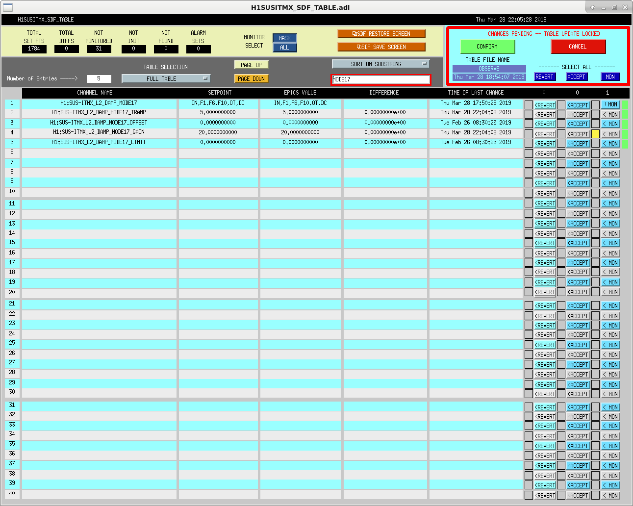
05:00 UTC I believe the violin mode guardian may have changed the gain for ITMX mode 17, which happened to be monitored in SDF, and this took us out of observing. I have unmonitored this channel in SDF (see attached screenshot) and put us back into observing.
We should unmonitor all of these gains (all guardian touched gains in Bank 1 and 2 of all optic violin mode damping banks). If someone gets a minute, please do so. Or we can do the ones that crop up and we'll finish cleaning house in the next few days.
These injections are scheduled to begin at 23:00:00 PDT 28 March 2018, the first injection should occur at 23:00:10 PDT 28 March 2018, and the entire excitation should last only 91 sec. The expected GPS times of all these injections can be found in GraceDb via: https://gracedb.ligo.org/search/?query=H1+Test+HardwareInjection+gpstime%3A+1237874418+..+1237874510+HWINJREQ&query_type=E&results_format=S
Schedule file was updated and INJ_TRANS was reloaded to pick up this injection. Unfortunately, this caused H1 to drop from observing.
The injections were successful. I've attached a CSV file with the expected injection paramters. They can also be discovered in GraceDb via: https://gracedb.ligo.org/search/?query=Test+H1+HardwareInjection+HWINJOK+1237874418+..+1237874518&query_type=E&results_format=S
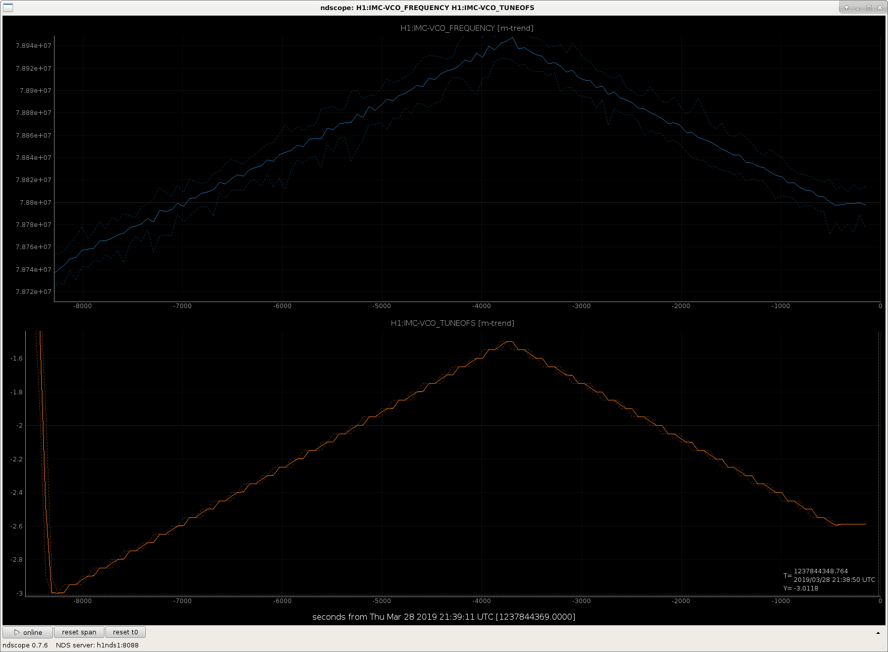
I have started another, somewhat slower IMC VCO sweep, in the frequency region around 78.8 MHz. Andy's plot in alog 47970 indicates that this is our best candidate for a whistle-free region.
I started moving the offset slider at about 19:16:50 UTC to get my starting place where I wanted it, a little low of 78.8 MHz. Then at about 19:23:35 UTC I started the script.
Picking upper and lower limits of the clean region of Andy's plot by eye, I'm sweeping the VCO between 78.8 MHz (-3.37 V) and 78.95 MHz (-1.48 V).
As with last night, this is a very slow change, and today we should be out of the whistle region for almost all of the sweep time, so we're leaving the IFO in Observing (with Keita's permission).
I've swept through the candidate VCO region once, and partially a second time. Since we've done a slow sweep in one direction, we're aborting the sweep-with-clean-data back in favor of some calibration measurements.
However, so that I don't accidentally cause any nasty glitches, I'm letting the VCO frequency continue to sweep, so anyone looking at the data will see that there is suddenly a lot of noise. Just stop looking at the data at around 21:21:00 UTC.
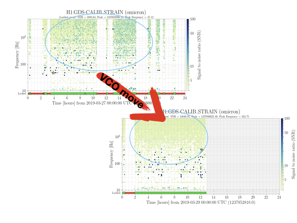
Also, by just looking at the DMT-Omega, it looks like there's definitely a major difference in the quantity of glitches reported as we sweep the frequency close to the edge of the clean region.
One sweep from -3V to -1.5V offset starts at 1237836061 and lasts for 4677 seconds.
VCO sweep started at 2019-03-28 12:23:37.922011 Pacific
VCO sweep ended at 2019-03-28 14:32:12.228220 Pacific (This is when I stopped the script - Cal injections started before this)
Also, Daniel looked at the glitch mon on the wall, and found that our cleanest region so far looks like it's when we're at -2.1 V. I have put us there, and then accepted that value in both the safe and observe snap files. The value is not monitored (maybe we should monitor it?!?), but at least now it'll come back to the correct value upon reboot.
With the VCO now around 78.86 MHz, there's no evidence of whistles in several hours of lock.
Craig Dan Danny Georgia + Jeff B and Ed
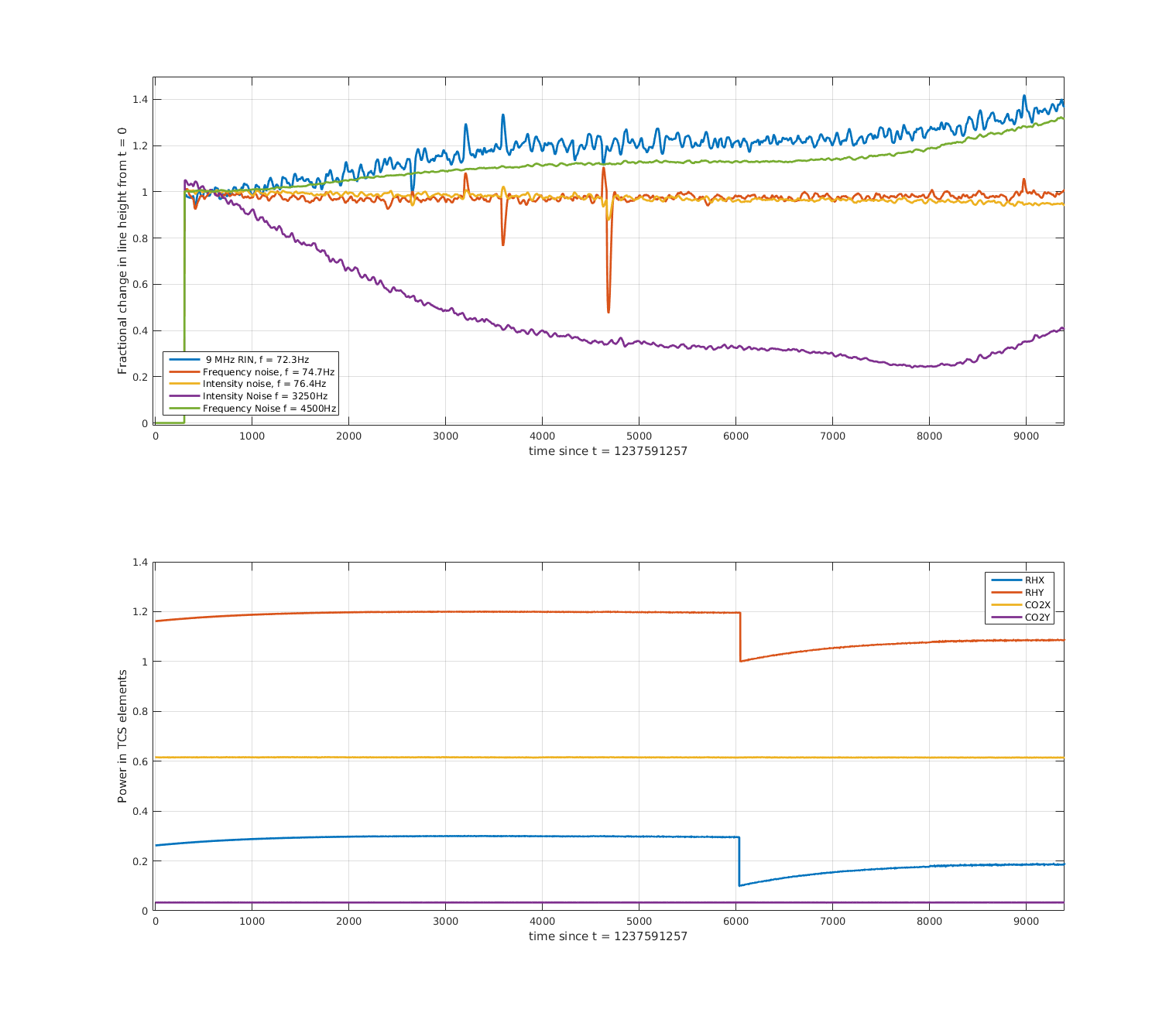
Over the past week we've taken a couple of steps with the ring heaters, trying to find a more optimal TCS configuration for 35 W input power. Craig and Dan previously set up the AWG_LINES guardian to inject frequency noise, intensity noise, and 9MHz RIN lines. I wrote a quick matlab script to demodulate these lines, and have made some plots of how these couplings change over time with the ring heater steps. This is building on an ipython notebook Dan had already written, but it cuts the data into chunks so it doesn't require the cluster to run. This work is ongoing but I'm posting what we've got so far.
It's a bit loose for now, but for interested TCS'ers, script lives here:
/ligo/home/georgia.mansell/TCS/AwgLineDemod/plotTCSDemodLines.m
On Monday Jenne decreased the ITM ring heaters in common by ~250 mW. She saw:
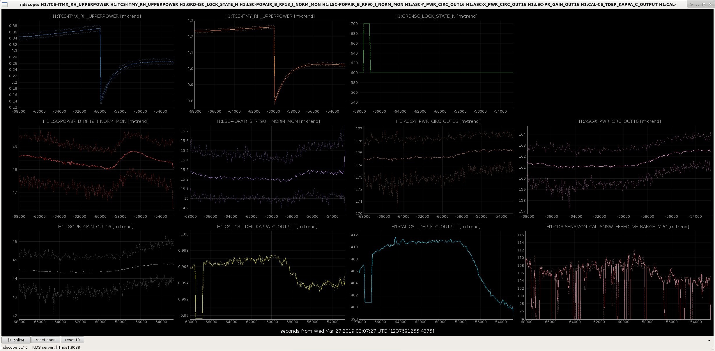
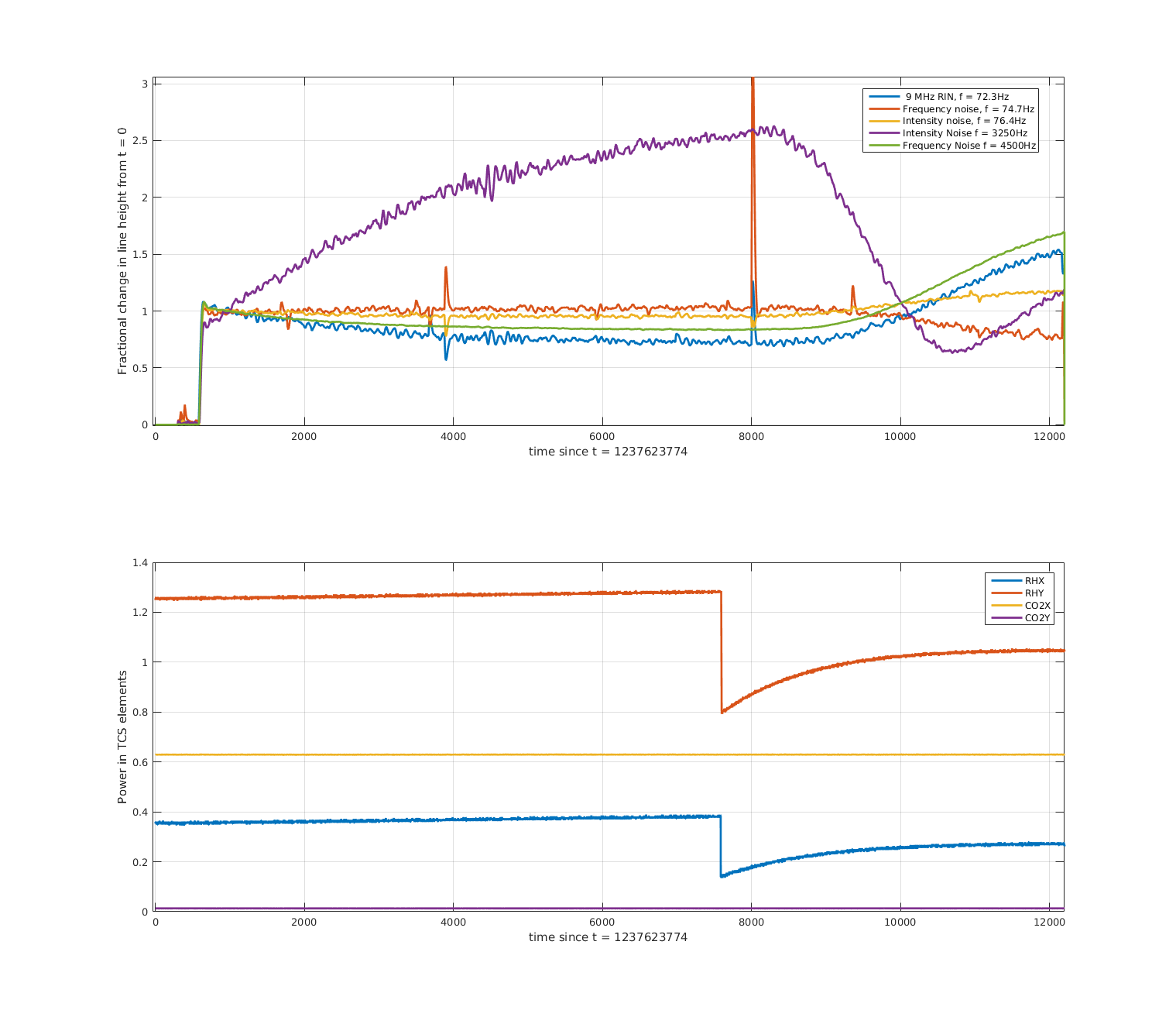
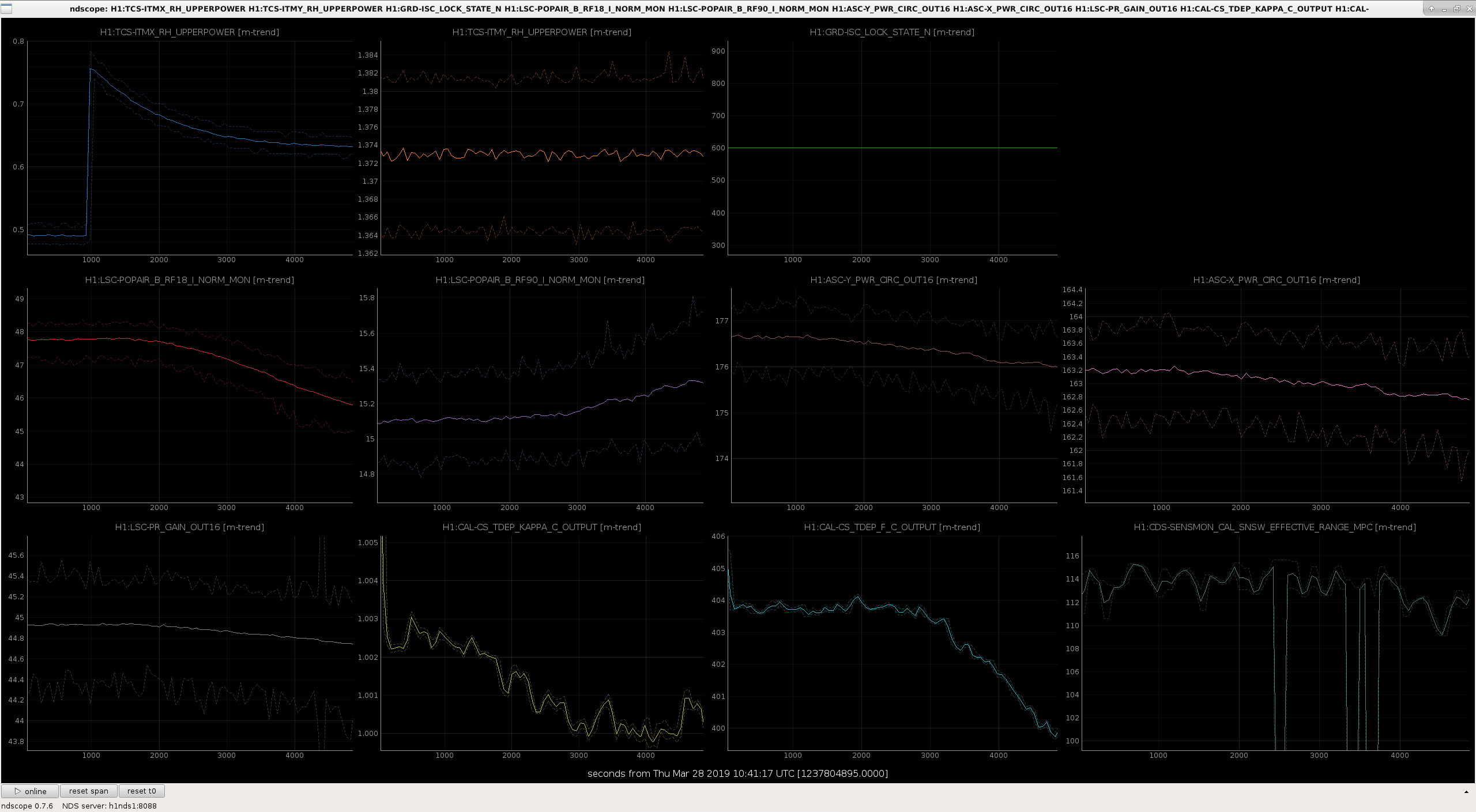
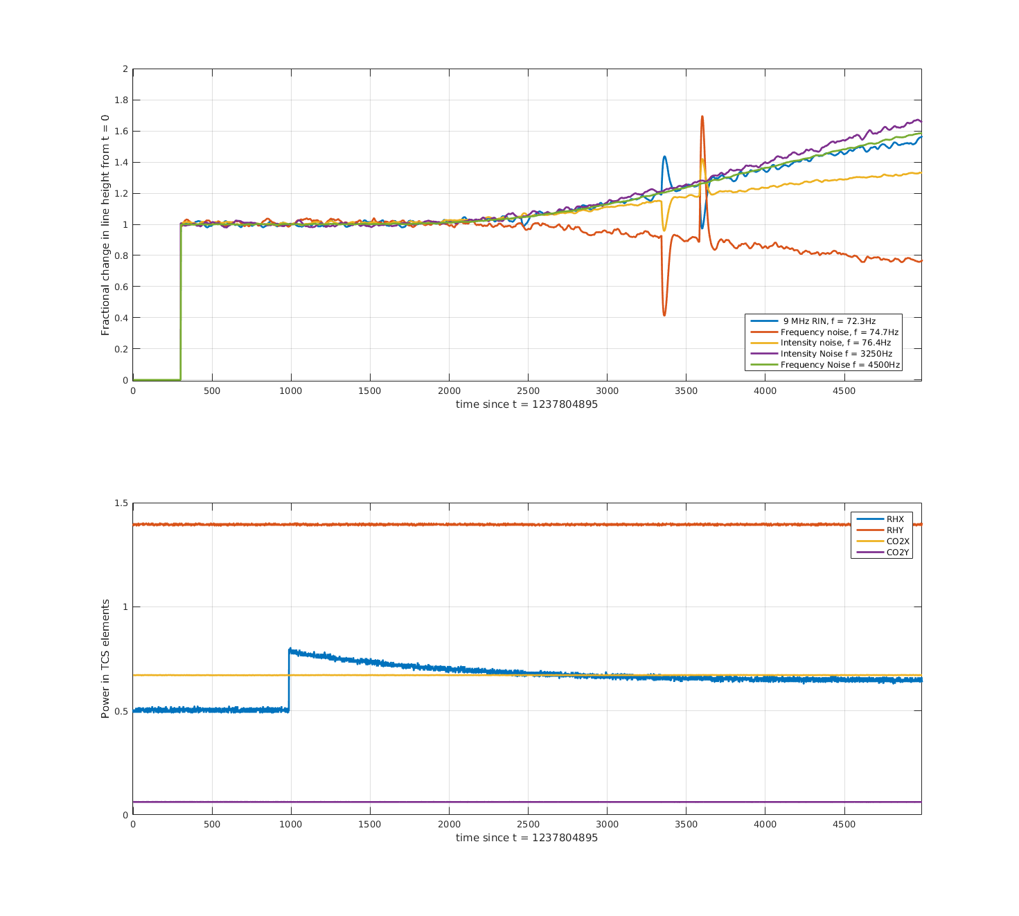
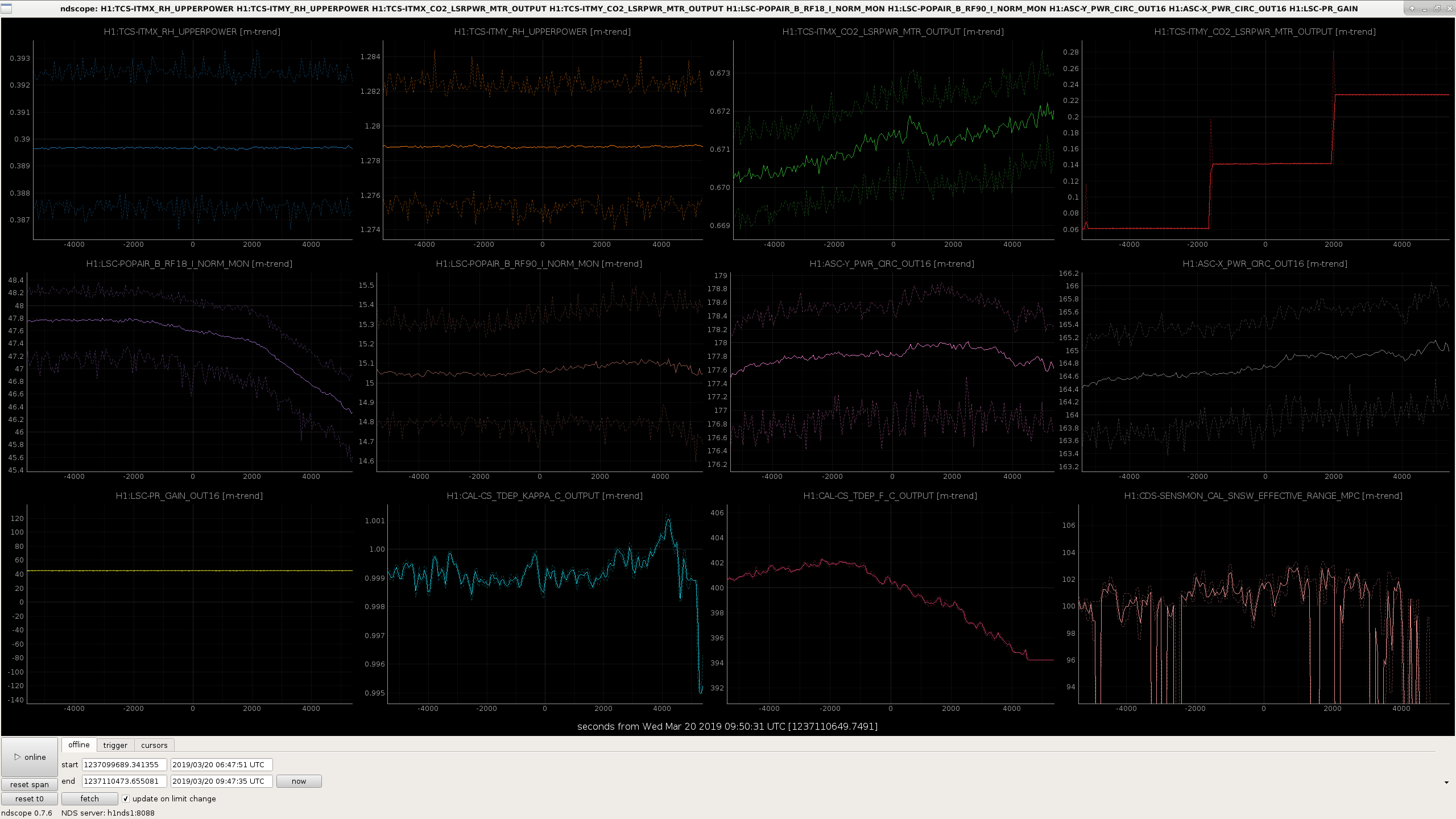
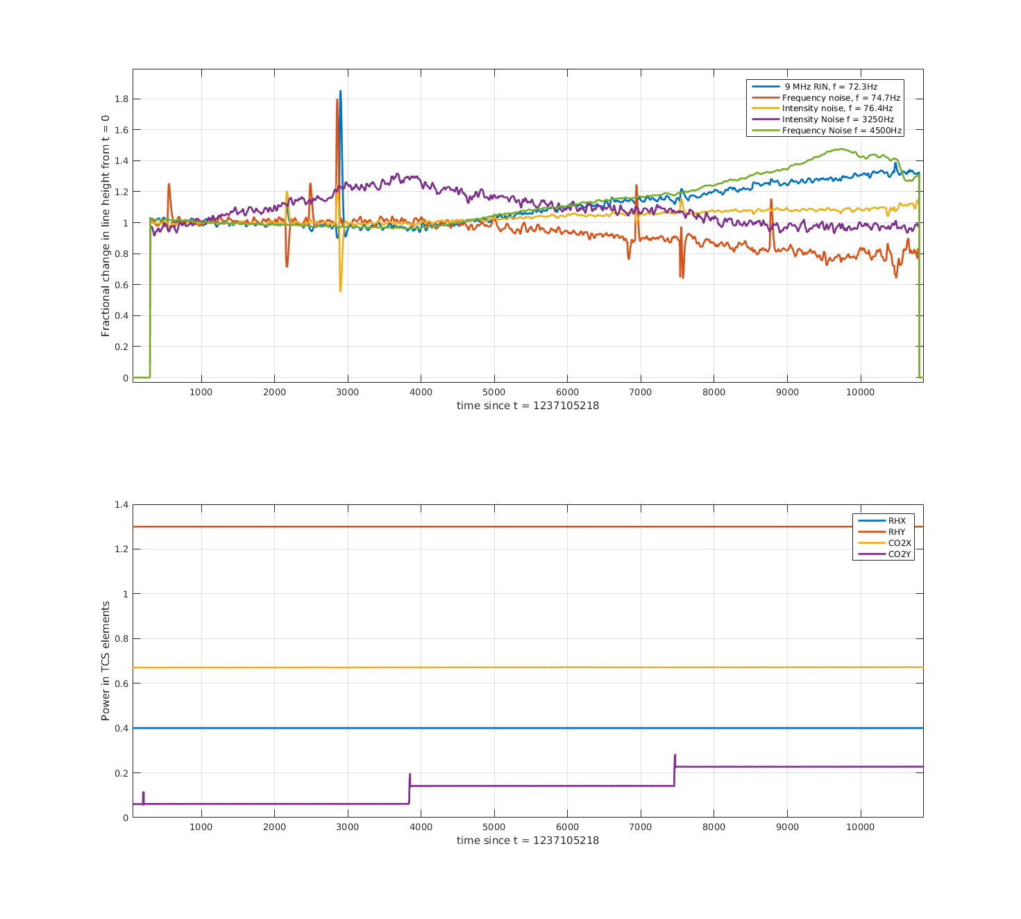
The first attachment shows an ndscope of the diagnostics, as well as the ring heater powers. The second attachment shows the demodulated lines, normalised to t ~ 700 s (sorry it's a bit dodgey for now). The time axis starts just after the first step down, at roughly the same time as the cursor in the first attachment (the lines were not on before this time), the lower plot shows the ring heater set_upper_power, which is controled by Danny's ring heater guardian.
The interferometer was well thermalised before this change, having been locked for 19 hours. Things to note: the coupling of the 9 MHz line, and high-frequency frequency noise appears to grow with this ring heater step. The high-frequency intensity noise coupling drops, though seems to turn back up towards the end - maybe we overshot some minimum coupling? The ring heater time constant is very slow. The frequency and intensity lines in the bucket seem unaffected.
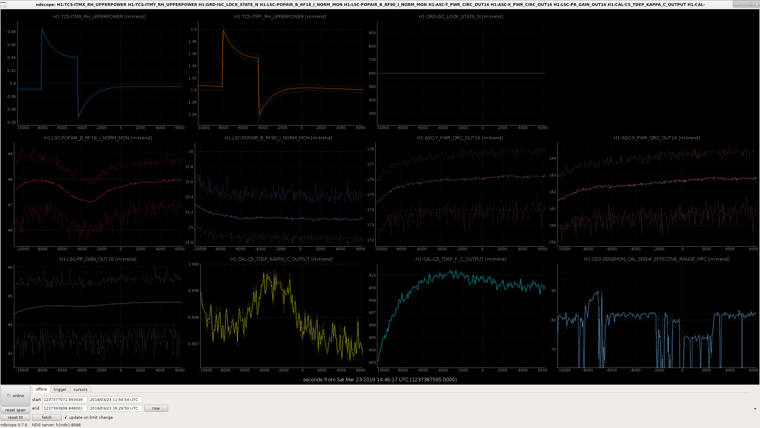
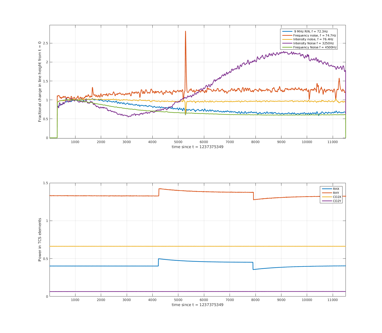
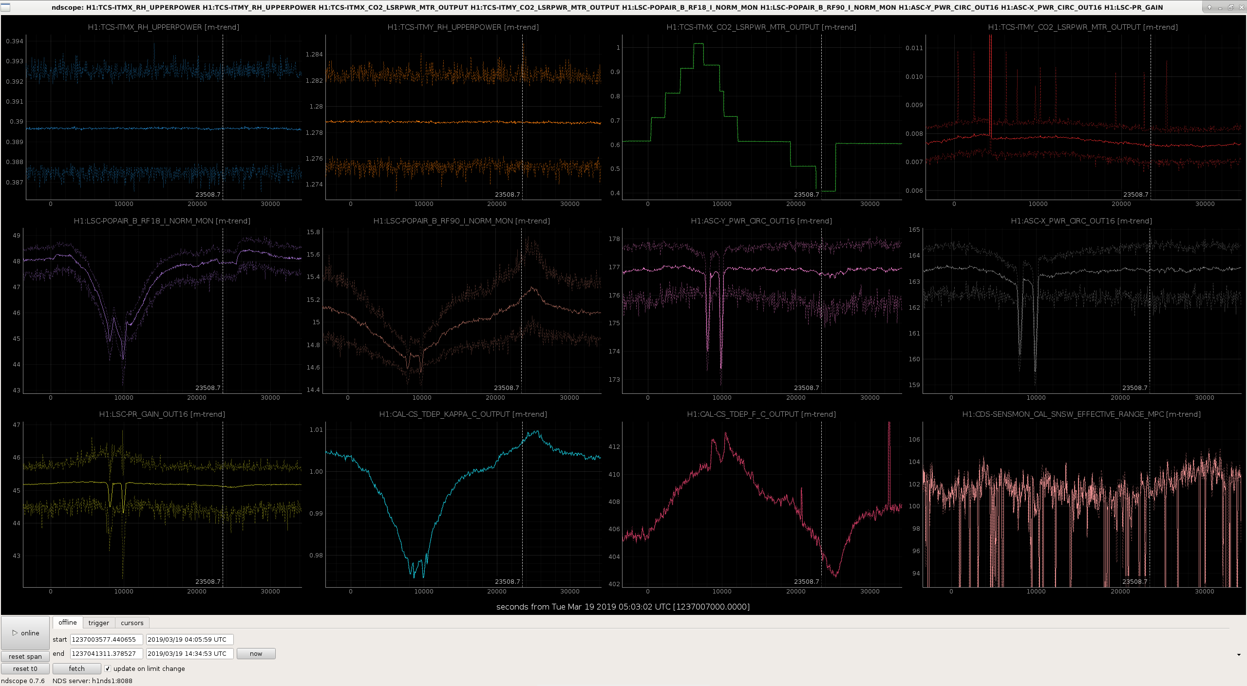
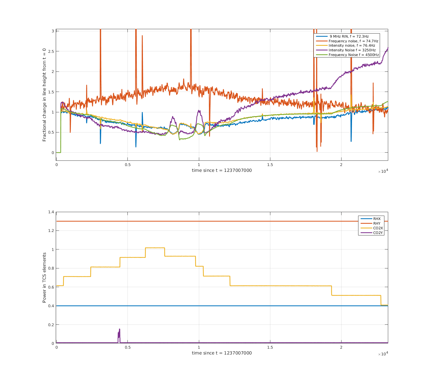
Later the same night, we tried a slightly differential step down in the ring heaters, lowering ITMX by ~0.1W and ITMY by ~0.26W. We see similar behaviour in our diagnostics (third attachment), increase in RF18 and circulating power, decrease in the f_c and range. Note that this step was taken sooner after locking, and that the interferometer was still thermalising. The fourth attachment shows the demodulated lines. Changes before the step at t~7500 are due to the thermalisation of the interferometer. After the ring heater step, the high frequency intensity noise again takes a dip (with a pretty fast time constant), while high-frequency frequency noise and RF9 increase. Craig noted that the high frequency line and the 9MHz RIN line (at 72.3 Hz) are moving together. With this step intensity noise in the bucket seems to rise, and frequency noise in the bucket seems improved.
On Friday night Danny and Ed took a 0.1 W common increase in the ring heater power. Note earlier that night we had seen that a 0.5 W increase on ITMY only caused POP_RF18 to plummet potentially causing a lockloss. During this step the interferometer was still thermalising, see for example RF90 (purple trace in fifth attachment) dropping before the ring heater step. I originally got excited to see the range increase but probably that was due to some squeezer shenanigans happening at the same time? With the increase in power RF18 looks like it drops a little, but other diagnostics don't show much. I think the demodulated lines (sixth attachment) are dominated by the thermalising IFO.
Tonight (@ 10:57:43 UTC) we have tried increasing the power on ITMX ring heater only, we requested 0.8 W from the filter input, where nominally it is 0.5 W. If future operators or commissioners would like to return this value to nominal after lockloss (eg if ASC is problematic), this can be done in the command line:
caput H1:TCS-ITMX_RH_INVERSE_FILTER_IN 0.5
The new custom mask has not been installed as far as I know. The testing, according to the mask guardian, has been done with the central mask.
The results from last night's RH_X step up by ~0.15W:
Overall, not good.
I've made the same plots of diagnostics and demodulated lines for some of the CO2 steps done last week by Dan and co.
Most of the analysis for this one was already done by Dan (alog 47658). First attachment shows the diagnostics, second attachment shows the demodulated lines. Some things to note
We did two tests around 20190320/21 with CO2Y power increasing, one with and one without the point absorber mask. The results were pretty similar. Third and fourth attachments are diagnostics and lines with the mask was one (the ifo had better thermalised for this test so the results are less confusing)
Based on all these test so far it's not obvious to me what combination of TCS settings we need to get the improvement we'd expect from out 30 - 35 W input power increase.
Was the second version of the CO2Y mask installed for this test? The first version is no longer valid due to the movement of the IFO beam.
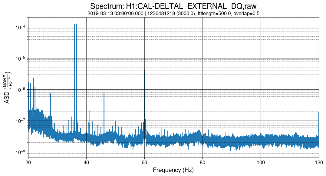
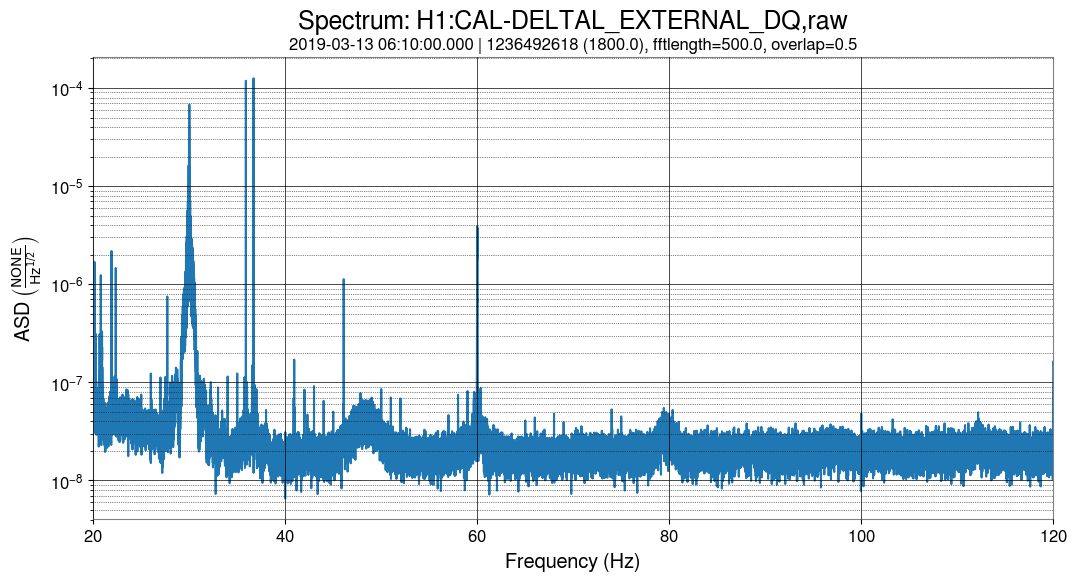
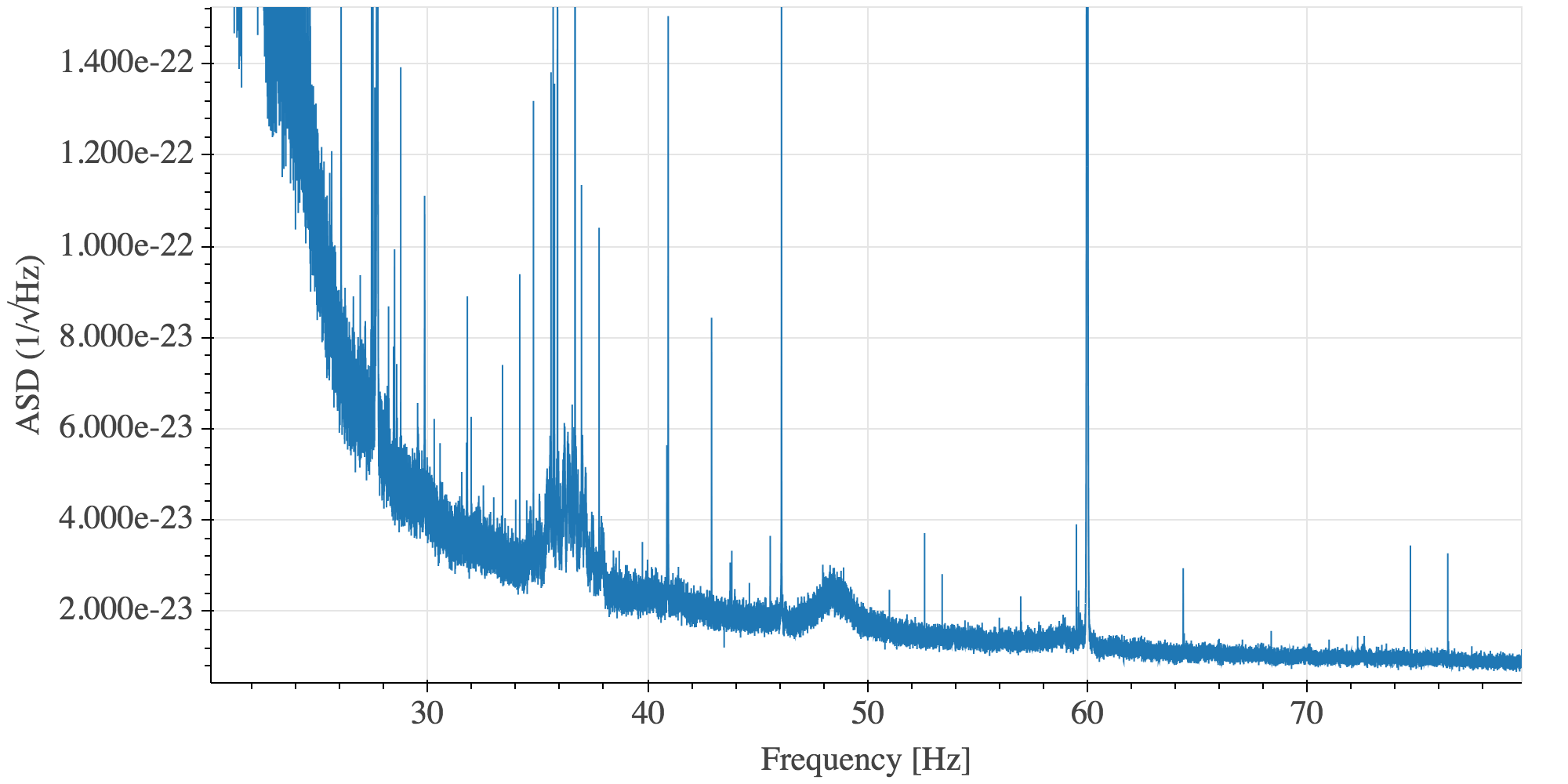
Given that H1 is still in commissioning mode, I hesitate to report on lines that may be due to ongoing work, but I'm seeing a very strong 1-Hz comb in DARM as of last Wednesday, which I suspect is unintended. Below are spectra of 20-120 Hz and its 20-Hz sub-bands from yesterday's data (typical of daily spectra since Wednesday). Note that the lines are on exact 1-Hz multiples (to ~0.5 mHz resolution), but they have flat shoulders of O(0.01 Hz) full width. An arbitrary but typical example at 34 Hz is shown. Also, the amplitudes of the lines do not fall entirely monotonically with frequency. There are clusters of lines with a spacing of roughly 7-8 Hz. Any ideas on what changed, perhaps during the last Tuesday maintenance?
Additional clue: there are small but noticeable changes in comb strength in a couple magnetometer channels at EX, in the same time frame. I'm not seeing anything similar in EY or CS mags. (The 1-Hz comb is present in many magnetometers; it's the change points that seems to be unique to EX.)
Hey all,
This looks similar to what we have seen in the past from the hartmann wavefront sensor cameras. It seems like we solved the issue by changing the camera power supplies. We can double check this by changing the HWS sync frequency at low noise and provide you with a gps time.
Sheila, Anamaria
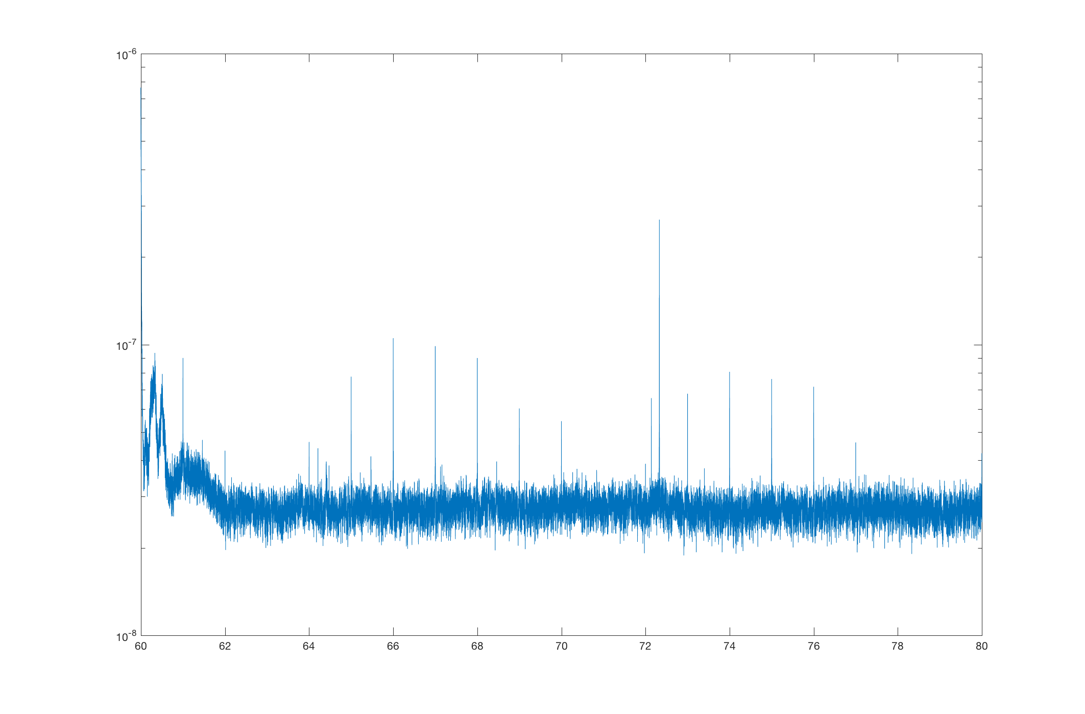
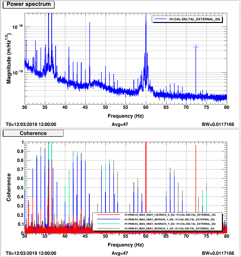
The first thing that comes to mind from last Tuesday is a change to the ESD driver grounding at EX (47308), which did reduce some coherence between EX magnetometers and DARM (47323) At first it looked like this work last tuesday removed a line at 73 Hz from DARM, although looking at the summary page you can see that this line has been coming and going and was at 72.5 Hz yesterday. summary page
It's probably not the HWS because those were always showing up a few tenths of a percent below their sync frequency, so if this comb is within half a mHz it's too accurate.
Ok, I'm posting more detail on what I'm seeing in the magnetometers, in case it helps to pin this down. I've checked for any obvious/clear change points, and also compared whether the shape of the comb is similar to what's observed in DARM (same pattern of variation in peak heights). In summary, SEIRACK and SUSRACK magnetometers at EX are particularly notable.
Also, the comb does appear to be precisely on 1 Hz, unlike the HWS comb.
Detailed magnetometer report:
[Corner station]
H1:PEM-CS_MAG_EBAY_LSCRACK_*_DQ: no apparent change; comb shape dissimilar from what is observed in DARM
H1:PEM-CS_MAG_EBAY_SUSRACK_*_DQ: no apparent change; comb shape dissimilar
H1:PEM-CS_MAG_LVEA_VERTEX_*_DQ: comb not really present
[End X]
H1:PEM-EX_MAG_EBAY_SEIRACK_X_DQ: changed (decrease); comb shape similar
H1:PEM-EX_MAG_EBAY_SEIRACK_Y_DQ: no apparent change; comb shape similar
H1:PEM-EX_MAG_EBAY_SEIRACK_Z_DQ: changed (increase); comb shape similar (?)
H1:PEM-EX_MAG_EBAY_SUSRACK_X_DQ: changed (increase); comb shape similar
H1:PEM-EX_MAG_EBAY_SUSRACK_Y_DQ: no apparent change; comb shape similar
H1:PEM-EX_MAG_EBAY_SUSRACK_Z_DQ: changed (decrease); comb shape similar (?)
H1:PEM-EX_MAG_VEA_FLOOR_*_DQ: comb not really present, but neither is anything else. These channels look way too clean; there might be an issue.
[End Y]
H1:PEM-EY_MAG_EBAY_SEIRACK_*_DQ: no apparent change; comb shape similar
H1:PEM-EY_MAG_EBAY_SUSRACK_*_DQ: no apparent change; comb shape similar
H1:PEM-EY_MAG_VEA_FLOOR_*_DQ: no apparent change; comb shape similar (?)
Robert, Anamaria
Even with just 0.01 Hz resolution, there is large coherence between various magnetometers in the EBAYs and DARM. Indeed this was not the case before last Tuesday.
Separately, the 72.5 Hz that appeared in the last two days is coherent with the corner EBAY magnetometer in the ISC rack. We think it's a real peak because if the sensor were picking up DARM the large calibration lines at 35ish Hz would show better coherence. Though it does not appear to be there this morning, so not completely clear what's going on.
Danny and I had a 72.33 Hz line driving some frequency noise over the weekend during some TCS tests. We also had lines at 3.25kHz, 4.5kHz and a bunch around 23-25Hz.
Shifted ETMX HWS sync frequency from 1 Hz to 5 Hz starting at 1236485181 and shifting it back to 1 Hz at 1236494796.
What about the GPS clocks that got turned on last Tuesday?
I had trouble finding a lot of clean DARM data during the period when the HWS frequency was changed, but what I found suggested the 1-Hz was still strong. Figure 1 is from when the HWS frequency was normal. Figure is from when it was changed.
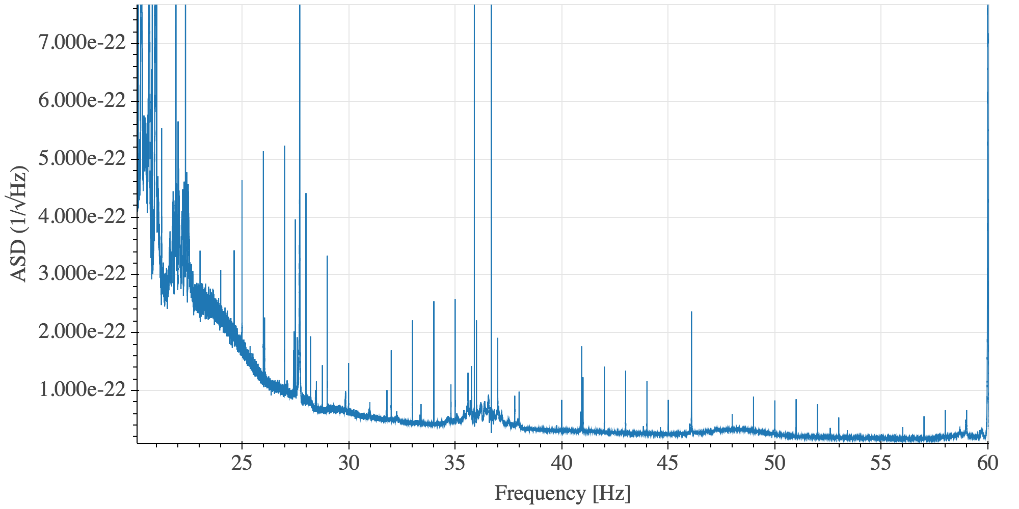
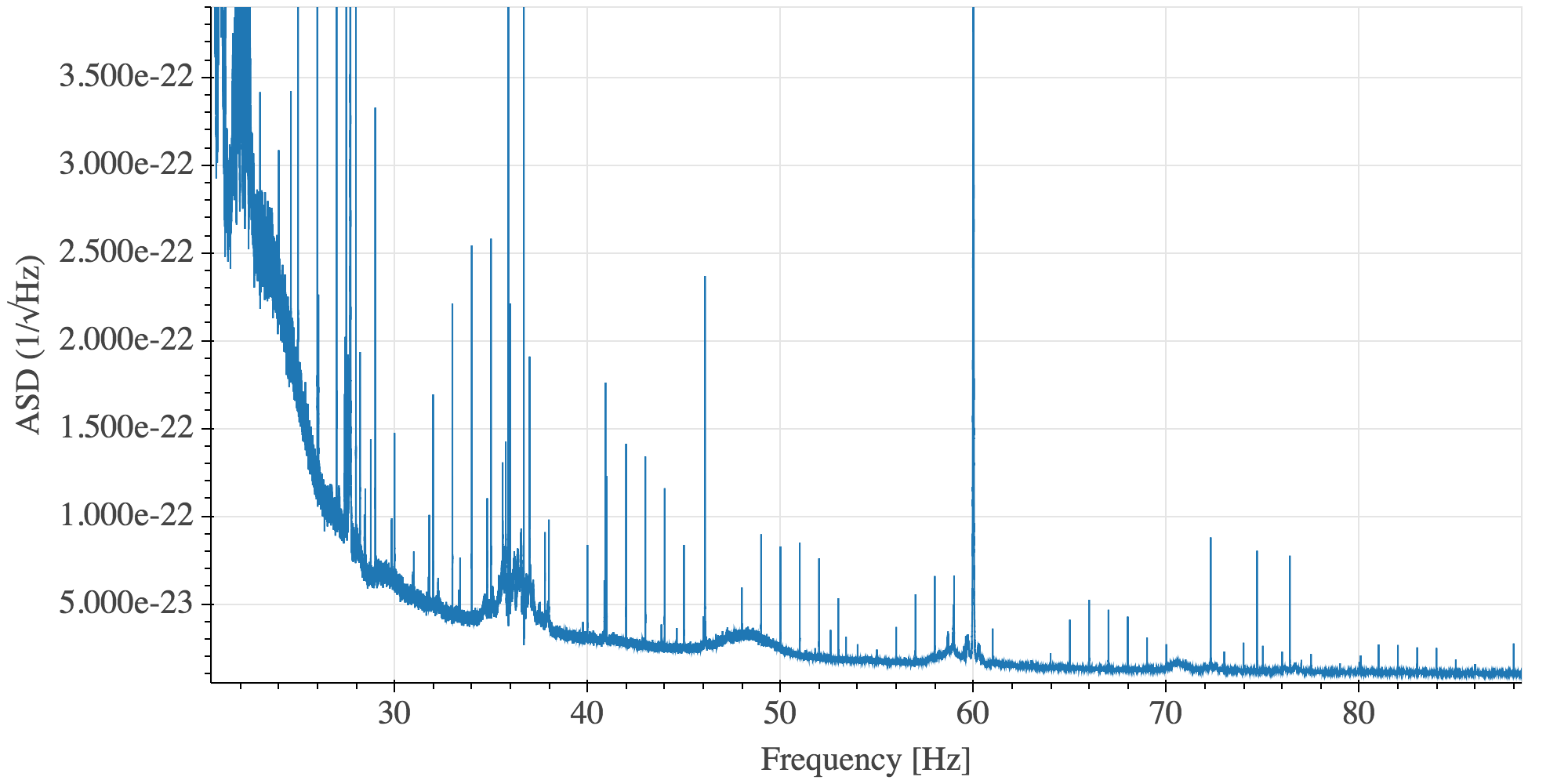
The 1 Hz comb is still present in data from the third week of ER14, see first attached plot. There is also a very bad 0.8 Hz comb visible between 420 and 500 Hz, see second plot.
The 0.8 Hz comb Pep noted is a complicated structure, but it has some symmetrical features which are centered on the 516.78 Hz line. Keith tells me this is an EX violin mode (alog 47650, alog 47179). A plot showing data from March 25 is attached.
It seems that the work reported in https://alog.ligo-wa.caltech.edu/aLOG/index.php?callRep=47766 has made the 1 Hz comb disappear.
The first attached plot shows the spectra before this change, and the second one the spectra after this change.
On the other side, the lines and 0.8 Hz comb around the ~500 Hz violin modes are still there.
In the attached figures (one with many signals, the other zoomed in on the signals that have a relevant change) show a reference time (dashed traces) from last night, when we did have our previously-nominal L2A filters and the PUM boost on versus our current lock without the L2A or PUM boost. You can see that all of the arm degrees of freedom (CHARD, DHARD, CSOFT, DSOFT and ADS) see much less motion at ~4 Hz, but the SOFT degrees of freedom see more motion at lower frequencies. This isn't too surprising since the L2A filters were measured with good coherence up to about 2 Hz, but not above there. On an upcoming Tuesday when we have time, we'd like to take data to get these L2A filters better coherence (JeffK started this Tuesday, but it's really hard to get good coherence).