betsy.weaver@LIGO.ORG - posted 15:30, Tuesday 26 March 2019 (47899)
IFO back up from Tuesday Maint
Nico and Ed have the IFO back up to Nom Low Noise. Calibration sweeps are currently running.
Nico and Ed have the IFO back up to Nom Low Noise. Calibration sweeps are currently running.
Daniel, Fil, Nutsinee
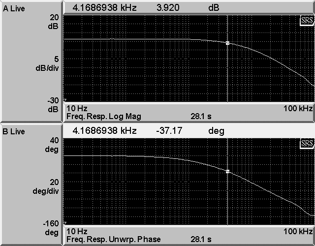
FEMTO LCA-S-400K-SI-FST was installed today (replace the unamplified Thorlabs diode that was in place). The following changes has been implemented on the concentrator board 7. Here's the transfer function.
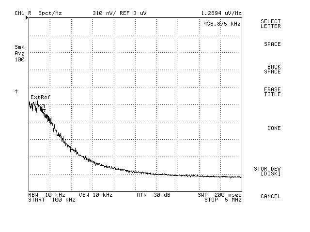
The response of the diode has also been measured (falls off at ~400kHz as advertised).
Nutsinee Daniel
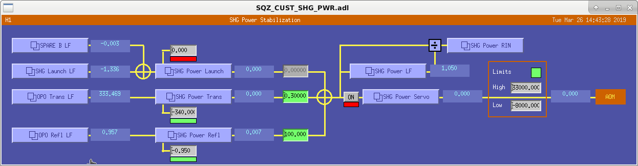
Asymmetric limits have been added to the green power servo to allow for lower power but limit the injected power to 20mW.
A new photodetector, Femto LCA-S-400K-SI-FST, has been installed in the OPO transmitted path.
The screenshot shows the updated servo screen.
Plot 1 shows the transfer function of this servo using the OPO reflected power (blue) and the OPO transmitted power (red).
Plot 2 shows the spectra of the OPO transmitted and reflected powers for servo off & optimized PDH offset (green), old PDH offset (blue), servo on using the transmitted power (brown), using reflected power (red) and the dark noise (black).
Plot 3 shows the coherence.
Earlier today I found that we have been operating with an offset in the common path. This offset was there because at the time when we swapped scheme the I error signal wouldn't go to 0 when OPO was locked (hence the offset was to zero this error signal). But only this morning I realized it caused a big offset in OPO refl and trans signal and we have been operating at the side of the fringe (and thus we have been sensitive to the OPO length noise, see 1.4 kHz peak, blue plot). Daniel found a new/better offset (1.45, was -4.125) which results in 11% more transmission and 16% less reflection from the OPO. And the OPO length noise diminished (red plot).
Richard Fil Ed Daniel
All VCOs and FDDs were equipped with the piggy-back board, which implements a relay to the power off the 1-GHz VCO, the RF dividers and the RF amplifiers. This required updated slow controls code and screens. There is a new button on the medm screen that turns on and off these RF parts. This replaces the excitation enable button which is now only available in hardware. So, there is still a readback of the state of the excitation switch. There are also new readbacks of the power state for VCO and FDD sections (corresponds to the two front panel power switches).
All VCO/FDD chassis have been upgraded in place with the exception of the squeezer VCO (s/n S1200565) which has been replaced with the spare (s/n S1700242).
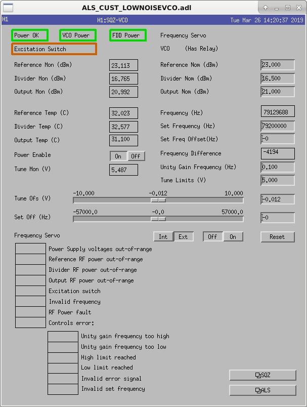
Per work permit 8142 we removed the 8 VCOs on site and added ckt board D1900056 to the chasis. This is a switch that allows them to be turned off remotely. https://dcc.ligo.org/DocDB/0159/D1900056/001/D1900056-v1.pdf.. Reinstalled the units and Daniel tested the software to make sure the switches worked.
Laser Status:
Front End Power is 31.67W (should be around 30 W)
70W Output Power is 70.37W
Front End Watch is GREEN
70W Watch is GREEN
PMC:
It has been locked 0 days, 0 hr 0 minutes (should be days/weeks)
Reflected power = 9.829Watts
Transmitted power = 54.48Watts
PowerSum = 64.31Watts.
FSS:
It has been locked for 0 days 0 hr and 0 min (should be days/weeks)
TPD[V] = 3.516V (min 0.9V)
ISS:
The diffracted power is around 2.1%
Last saturation event was 0 days 0 hours and 5 minutes ago (should be days/weeks)
Possible Issues: This looks good, up time is reflecting the end of Maintenance.
Both buildings were swept per the Sweep wiki/document.
Hugh made a walkthru of the LVEA for mech interferences to ISI/OPLEVs. Looks clear now.
WP8118 DAQ switch upgrade
Dave:
At EY I removed the old netgear switch and mounted the new Brocade switch in its place (last week I had installed the Brocade temporarily, resting on top of the Netgear). This took longer than anticipated due to inaccessible screws severely torqued down.
I have some more data points on what happens to DAQ data when an end station is shutdown. Last week powering off the netgear caused all FECs on h1dc0-card1 to go bad (both end stations, and most of corner ISC). This morning I tried just disconnecting a single front end (h1iscey) from the switch, again this hosed everything on h1dc0-card1. So I gave up trying to nicely and slowly remove FECs and powered down the EY switch, this time only EY went bad, as originally expected. I'm not sure why this behavior is inconsistent.
fmcs-epics-cds upgrade/reboot
Carlos:
The FMCS EPICS IOC machine fmcs-epics-cds was rebooted. The code did not automatically restart. I stopped the alarms, restarted the FMCS IOC and restored the alarms. The IOC was burt restored to 7am.
WP8141 h1sqz model change
Nutsinee, Daniel:
a new h1sqz model was installed. DAQ restart was required.
WP8137 remove PSL-DBB Jitter IPC from h1lsc
Dave:
I installed a new h1lsc model, removing the Dolphin IPC receiver for the PSL-DBB Jitter signal (which has been unavailable since mid-2018 when the Dolphin card was removed from h1psl0). This has greened up the IPC status, allowing me to show it again on the CDS overview. DAQ restart was required.
DMT Nat router upgrade
Carlos, Ryan, Dan:
A new nat router was installed for marble in place of the aging X2200 which was showing a failure LED. The original 10G SFPs did not work in the new hardware, and downgrading the SFP to various types of 1GB was unsuccessful. The original X2200 was put back into place for now. It is no longer showing a failure LED.
Beckhoff upgrades
Daniel, Dave:
Daniel installed new Beckhoff code, resulting in new DAQ-INI files for C1PLC[2,4], Y1PLC[1,2], X1PLC2. DAQ restart was required.
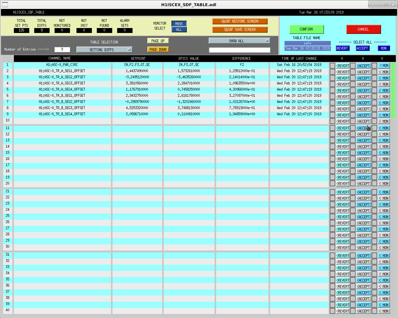
Some of the Beckhoff SDF faux-models were unresponsive, I restarted them all on h1ecatmon0. For each new channel which was not initialized, I (ACCEPT+MONITOR)'ed them.
Not Done This Week:
Ran out of time due to unexpected difficulties meant that external EDCU, DMT cable cleanup and EX switch upgrade will be deferred to next maintenance or TOO.
h1lsc on overview no longer has its IPC notched out.

Restart log for this morning's activities. Note that beckhoff PLC restarts are not logged here. All times PDT, we overran end-of-maintenance by 35 mins.
Maintenance activities ended around 12:30, a few of the items have been deferred.
Going through initial alignment now.
Pep Covas, T. Shaffer
Started the HIGH_FREQ_LINES Guardian node to sweep H1:CAL-PCALX_PACALOSC1_OSC_FREQ from starting frequency to 2000Hz by 500Hz steps. The steps will happen every 12 hours, but it will wait until we are not locked to change the frequency, so it could be longer than the 12.
Line amp = 35000
Starting freq = 5950.0Hz
Step size = 500Hz
We unmonitored H1:CAL-PCALX_PCALOSC1_OSC_FREQ in SDF.
J. Kissel, P. Covas
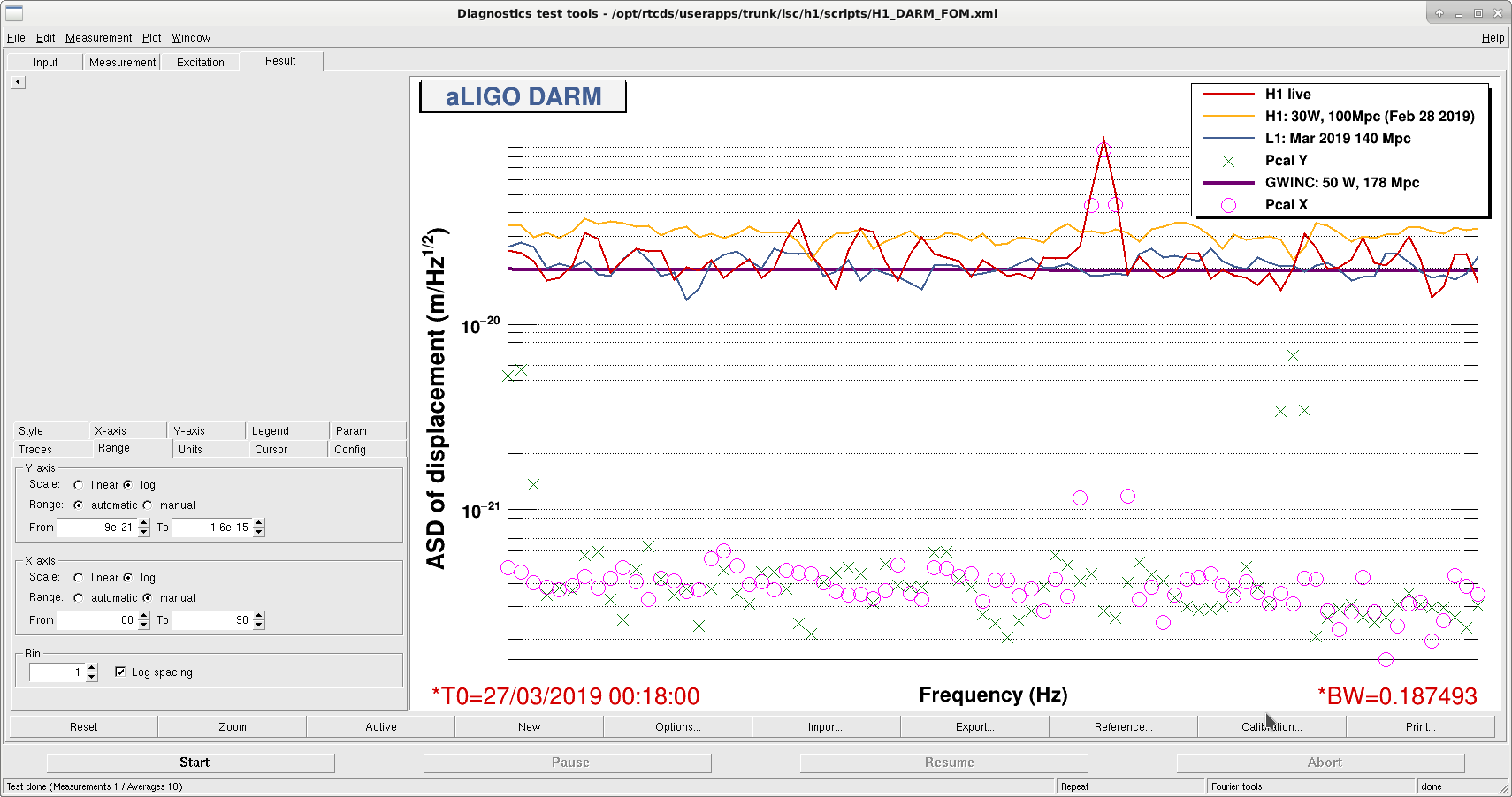
We found that the PCALX saturated, so we turned off the line at 5950.0 Hz, then turned off the optical follower servo and then reenabled it. Then we turned up the line around 0:18 UTC. We saw the non-linearity (down-conversion) seen previously in O2 is still there, which produces a line at 86 Hz, as can be seen in the attached plot. At 0:24:45 the frequency of the line was changed to 3 kHz.
We have seen that the line had been reverted back to ~6kHz. At 18:47 UTC we have changed it to 3001.3 Hz
FRS8295 Closed
After a myriad of minor issues for the past ~5 Tuesdays, I finally have the new RTD working.
I've restarted the FMCS-EPICS IOC and burt restored to 07:00 PDT. There should be no further alarms.
Sheila, JeffK, Betsy
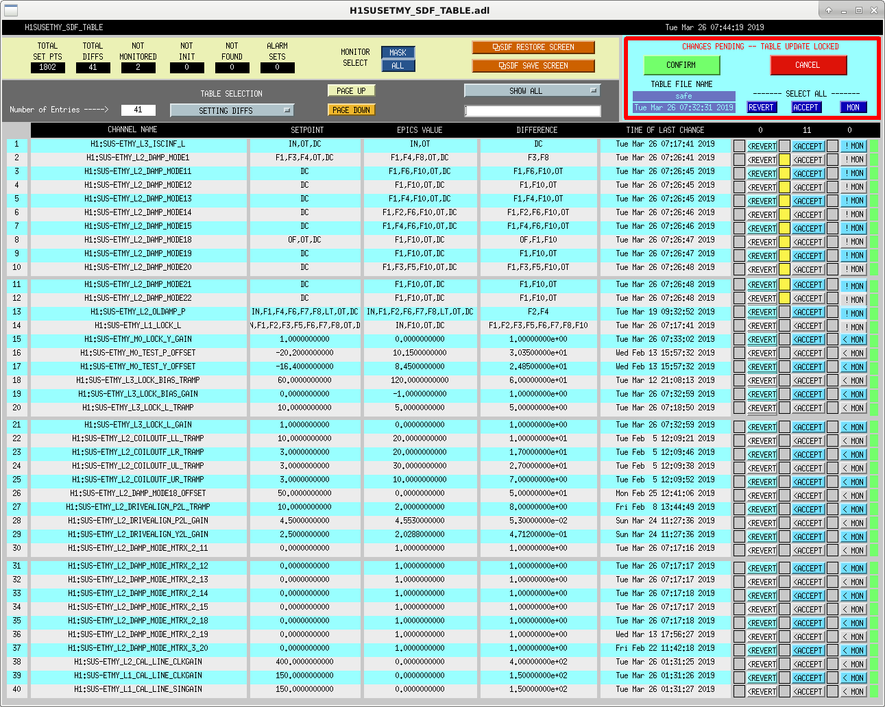
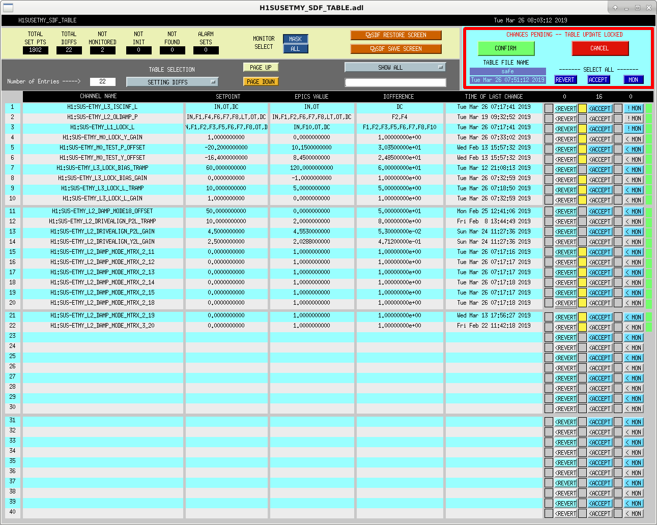
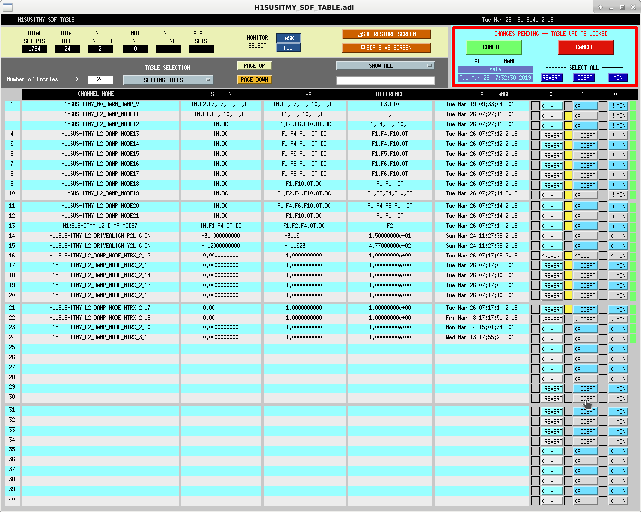
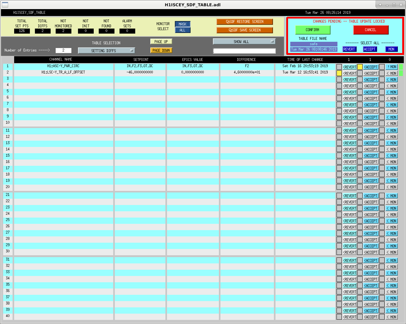
With the IFO set to Down after a fresh lockloss, we tackled setting the SAFE SDF files across all SUS, LSC, ASC, etc files (in prep for lsc, tcs, sqz, guardian to all be restarted this am). We generally accepted all things that guardian had newly set this morning, accepted all new Damping matrices settings, reverted some A2L settings from an errant script run over the weekend, and Sheila hand accepted/reverted a handful of things that were not well logged but that she thought seemed appropriate.
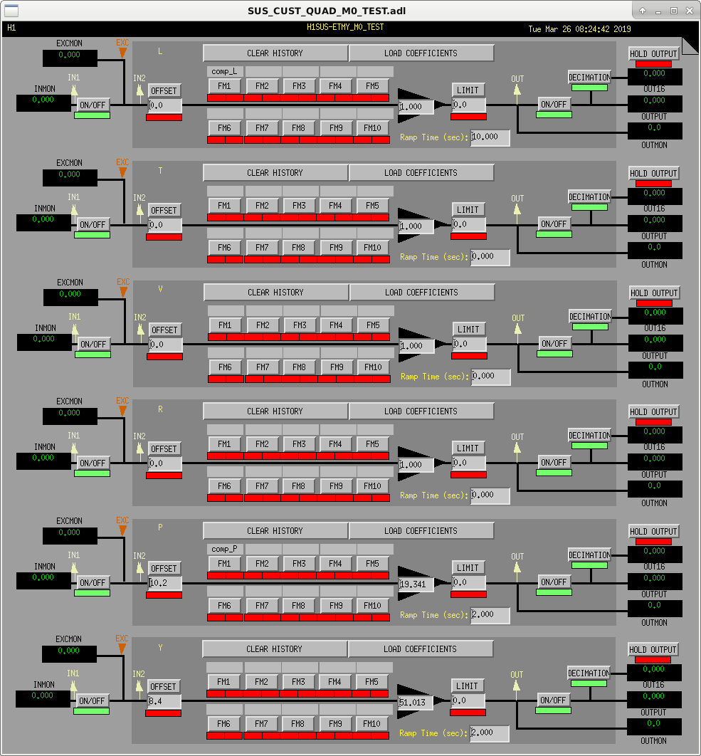
We found new ETMY_M0_TEST_OFFSETS changed Feb 13, but not logged. We decided to leave them, but are unsure of where they came from. See snapshot.
Once IMC setting files were sorted, Jeff set the IMC to OFFLINE for the VCO cards to be pulled (scheduled maint item).
I accidentally ACCEPTED 3 settings on the HAM2 ISI OBSERVE file, so those will pop back up in OBSERVE and will need ACCEPTING to get them back to the correct state.
We ignored all Beckhoff SDF files since Daniel had already started work on them and didn't want us changing the files.

Craig, Georgia, Nutsinee
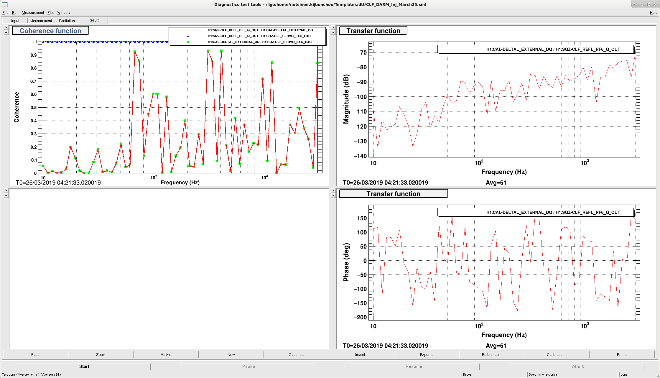
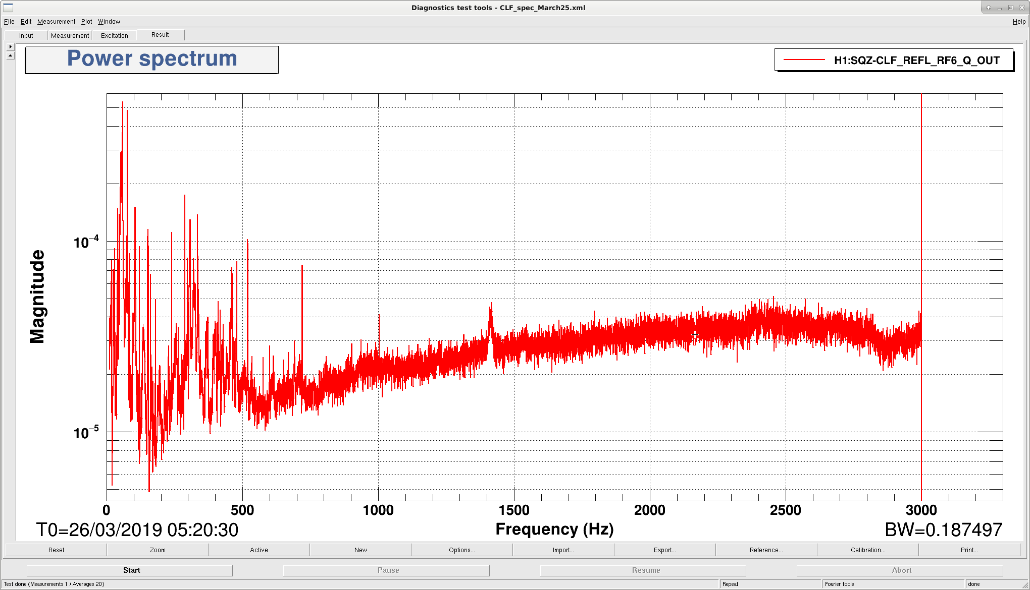
It seems like we have non-linear coupling from CLF to DARM. The coherence plot wasn't very obvious but we clearly saw out injection showed up everywhere in DARM as we swept. Lockloss before we could inject more squeezing measurement (it's not the squeezer!).
Hmm. How hard were you driving? I suppose it's either fringe-wrapping or nonlinear upconversion of the backscatter. At LLO, driving the ZM's also shows such nonlinear conversion into DARM LLO43807
The relevant ZM1 drive plot in DARM.(DARM calibration not setup here, but you can clearly see the 2F and even 3F harmonics for a small 1F drive)
I assume we are modulating the back scattered light, so the phase wanders around. We will have to repeat this with a power spectrum peak height ratio measurement.
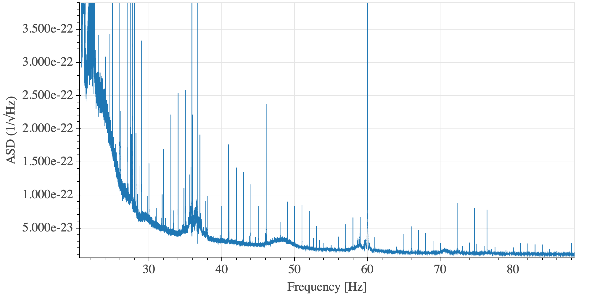
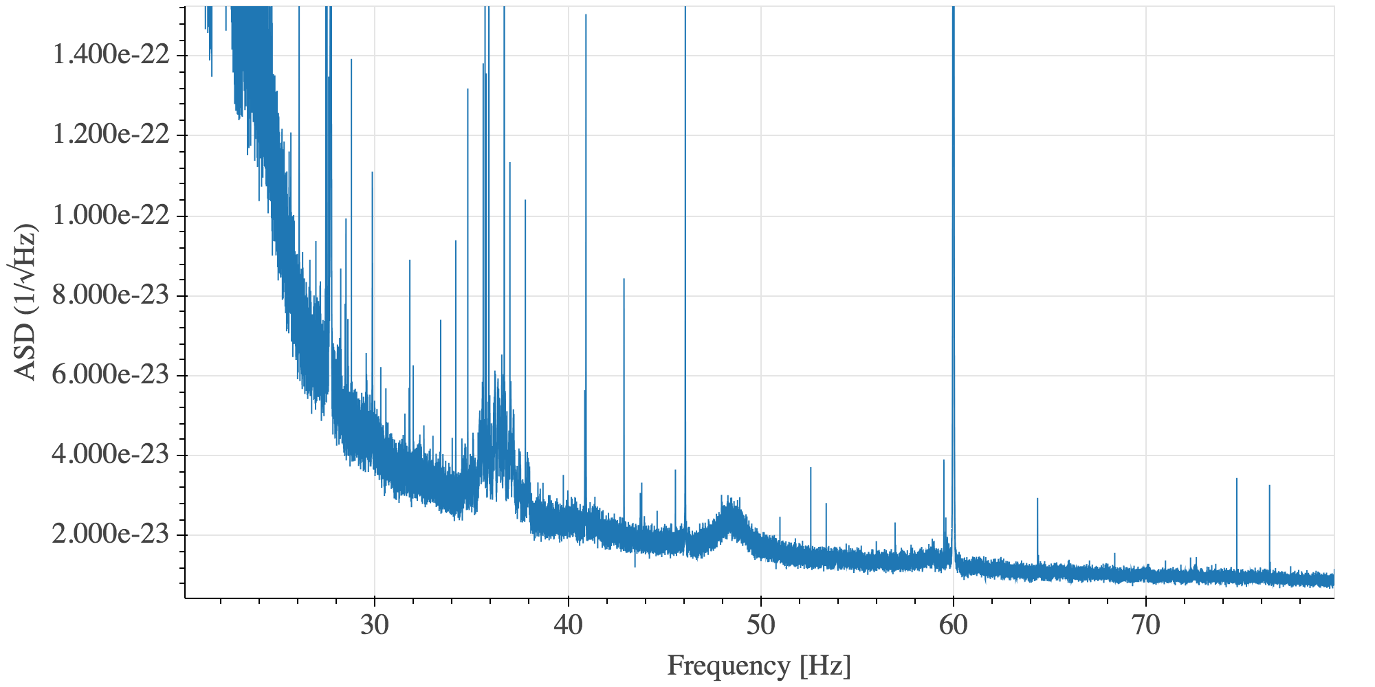
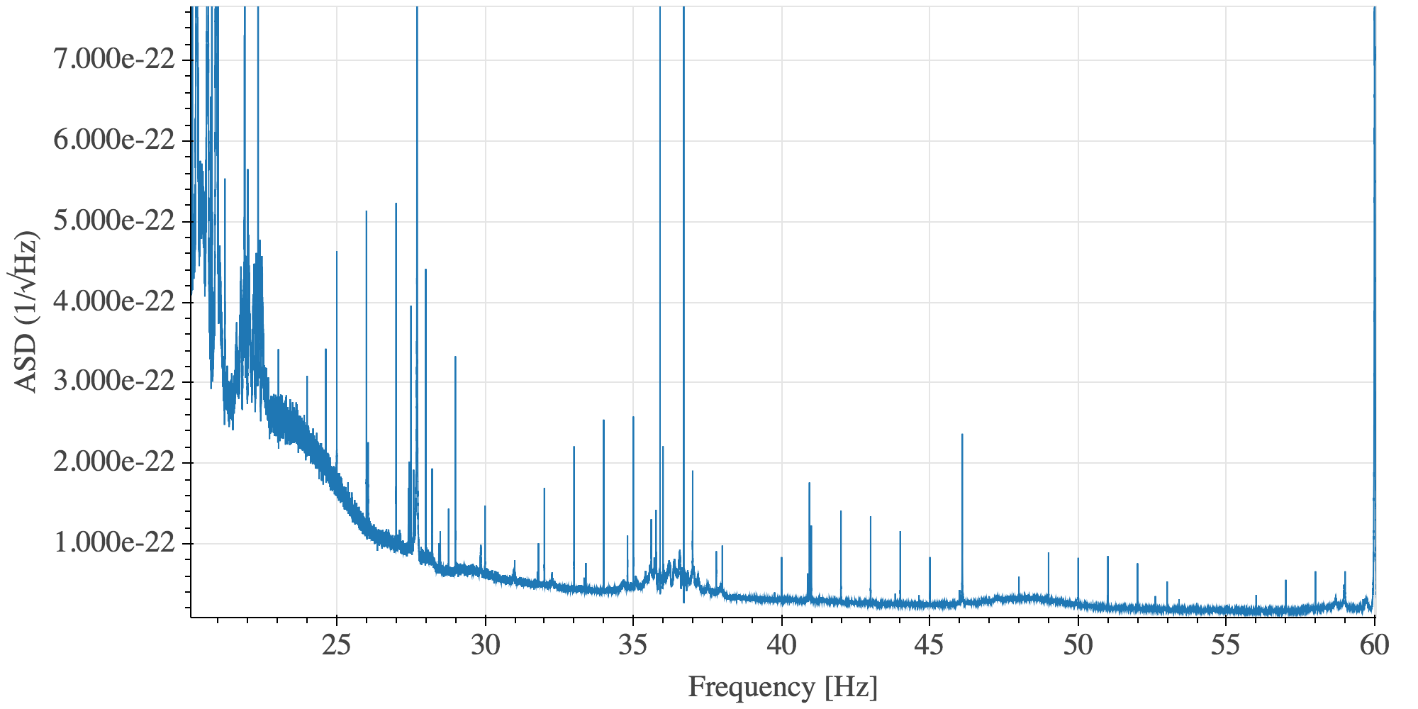
Given that H1 is still in commissioning mode, I hesitate to report on lines that may be due to ongoing work, but I'm seeing a very strong 1-Hz comb in DARM as of last Wednesday, which I suspect is unintended. Below are spectra of 20-120 Hz and its 20-Hz sub-bands from yesterday's data (typical of daily spectra since Wednesday).

Note that the lines are on exact 1-Hz multiples (to ~0.5 mHz resolution), but they have flat shoulders of O(0.01 Hz) full width. An arbitrary but typical example at 34 Hz is shown.

Also, the amplitudes of the lines do not fall entirely monotonically with frequency. There are clusters of lines with a spacing of roughly 7-8 Hz.

Any ideas on what changed, perhaps during the last Tuesday maintenance?


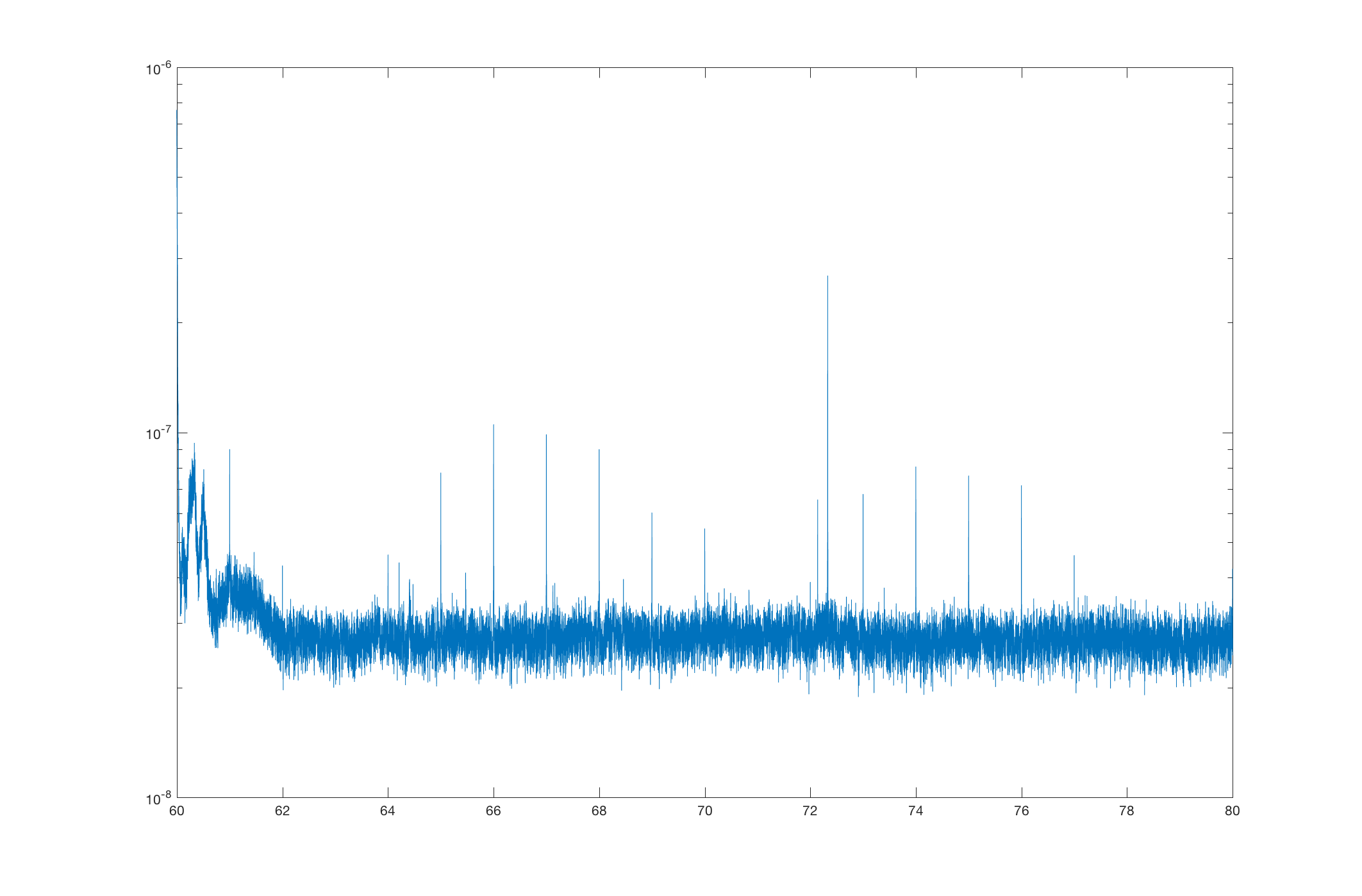


Additional clue: there are small but noticeable changes in comb strength in a couple magnetometer channels at EX, in the same time frame. I'm not seeing anything similar in EY or CS mags. (The 1-Hz comb is present in many magnetometers; it's the change points that seems to be unique to EX.)
Hey all,
This looks similar to what we have seen in the past from the hartmann wavefront sensor cameras. It seems like we solved the issue by changing the camera power supplies. We can double check this by changing the HWS sync frequency at low noise and provide you with a gps time.
Sheila, Anamaria
The first thing that comes to mind from last Tuesday is a change to the ESD driver grounding at EX (47308), which did reduce some coherence between EX magnetometers and DARM (47323) At first it looked like this work last tuesday removed a line at 73 Hz from DARM, although looking at the summary page you can see that this line has been coming and going and was at 72.5 Hz yesterday. summary page
It's probably not the HWS because those were always showing up a few tenths of a percent below their sync frequency, so if this comb is within half a mHz it's too accurate.
Ok, I'm posting more detail on what I'm seeing in the magnetometers, in case it helps to pin this down. I've checked for any obvious/clear change points, and also compared whether the shape of the comb is similar to what's observed in DARM (same pattern of variation in peak heights). In summary, SEIRACK and SUSRACK magnetometers at EX are particularly notable.
Also, the comb does appear to be precisely on 1 Hz, unlike the HWS comb.
Detailed magnetometer report:
[Corner station]
H1:PEM-CS_MAG_EBAY_LSCRACK_*_DQ: no apparent change; comb shape dissimilar from what is observed in DARM
H1:PEM-CS_MAG_EBAY_SUSRACK_*_DQ: no apparent change; comb shape dissimilar
H1:PEM-CS_MAG_LVEA_VERTEX_*_DQ: comb not really present
[End X]
H1:PEM-EX_MAG_EBAY_SEIRACK_X_DQ: changed (decrease); comb shape similar
H1:PEM-EX_MAG_EBAY_SEIRACK_Y_DQ: no apparent change; comb shape similar
H1:PEM-EX_MAG_EBAY_SEIRACK_Z_DQ: changed (increase); comb shape similar (?)
H1:PEM-EX_MAG_EBAY_SUSRACK_X_DQ: changed (increase); comb shape similar
H1:PEM-EX_MAG_EBAY_SUSRACK_Y_DQ: no apparent change; comb shape similar
H1:PEM-EX_MAG_EBAY_SUSRACK_Z_DQ: changed (decrease); comb shape similar (?)
H1:PEM-EX_MAG_VEA_FLOOR_*_DQ: comb not really present, but neither is anything else. These channels look way too clean; there might be an issue.
[End Y]
H1:PEM-EY_MAG_EBAY_SEIRACK_*_DQ: no apparent change; comb shape similar
H1:PEM-EY_MAG_EBAY_SUSRACK_*_DQ: no apparent change; comb shape similar
H1:PEM-EY_MAG_VEA_FLOOR_*_DQ: no apparent change; comb shape similar (?)
Robert, Anamaria
Even with just 0.01 Hz resolution, there is large coherence between various magnetometers in the EBAYs and DARM. Indeed this was not the case before last Tuesday.
Separately, the 72.5 Hz that appeared in the last two days is coherent with the corner EBAY magnetometer in the ISC rack. We think it's a real peak because if the sensor were picking up DARM the large calibration lines at 35ish Hz would show better coherence. Though it does not appear to be there this morning, so not completely clear what's going on.
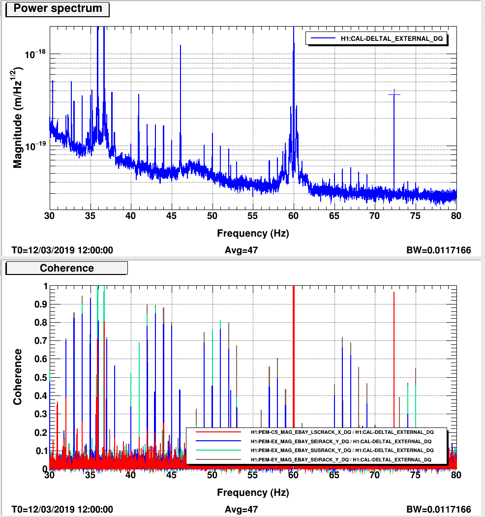
Danny and I had a 72.33 Hz line driving some frequency noise over the weekend during some TCS tests. We also had lines at 3.25kHz, 4.5kHz and a bunch around 23-25Hz.
Shifted ETMX HWS sync frequency from 1 Hz to 5 Hz starting at 1236485181 and shifting it back to 1 Hz at 1236494796.
What about the GPS clocks that got turned on last Tuesday?
I had trouble finding a lot of clean DARM data during the period when the HWS frequency was changed, but what I found suggested the 1-Hz was still strong. Figure 1 is from when the HWS frequency was normal. Figure is from when it was changed.
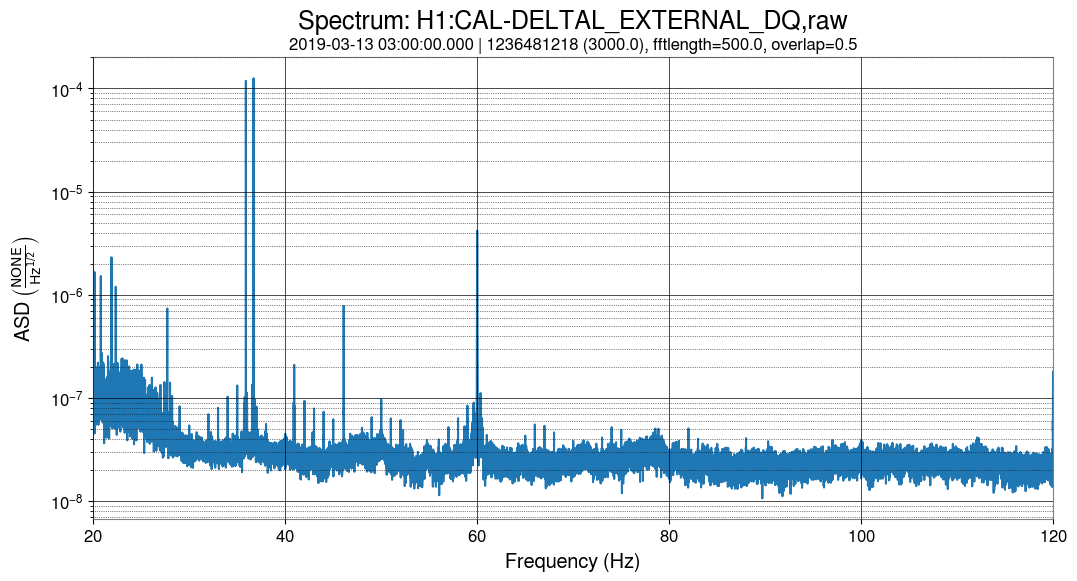
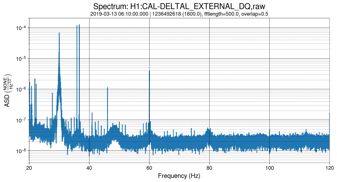
The 1 Hz comb is still present in data from the third week of ER14, see first attached plot. There is also a very bad 0.8 Hz comb visible between 420 and 500 Hz, see second plot.

The 0.8 Hz comb Pep noted is a complicated structure, but it has some symmetrical features which are centered on the 516.78 Hz line. Keith tells me this is an EX violin mode (alog 47650, alog 47179). A plot showing data from March 25 is attached.

It seems that the work reported in https://alog.ligo-wa.caltech.edu/aLOG/index.php?callRep=47766 has made the 1 Hz comb disappear.
The first attached plot shows the spectra before this change, and the second one the spectra after this change.
On the other side, the lines and 0.8 Hz comb around the ~500 Hz violin modes are still there.