NikoL, RickS
First, we re-installed the transmitter module shutter (Lasermet S/N 1258) that had been repaired by Filiberto and RichardM).
Then, we proceeded to investigate the clipping that had been reported based on observation of peaks in the Pcal Rx sensor signal ASD displayed in the control room.
We found that the outer (lower) Pcal beam was WAY off center (beam to the right in the first attached photo) at the Rx module power sensor. Since doing in-chamber alignment of the Pcal beams at all four end stations, this is the first time we have seen significant beam movement at the Rx power sensor.
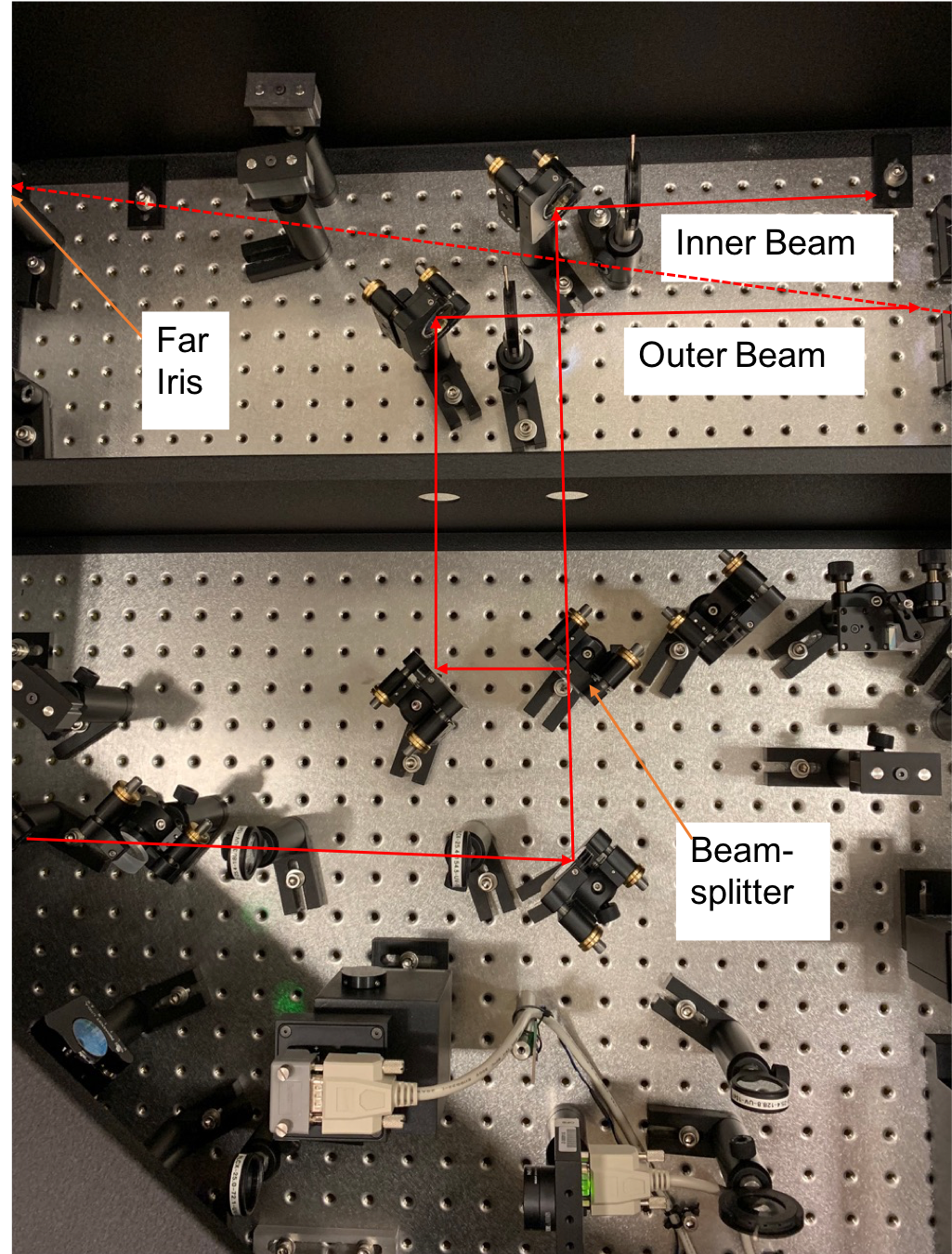
Inspection of the alignment irises revealed that the Outer Beam pointing was also significantly off (several mm left of center) on the far iris (see second attached image), with the temporary, kinematically-mounted retro-reflecting mirror in place (fourth attached image shows optical layout in Tx module).
Given that the inner beam had not moved at the Rx sensor, and that the pointing was off in the Tx sensor, it seemed that either the beamsplitter or one of the two downstream mirrors that direct the Outer Beam out of the Tx module had moved.
The attached video shows that the BS mount moves significantly, and much more than expected, in response to rocking forces applied at the top of the mirror mount.
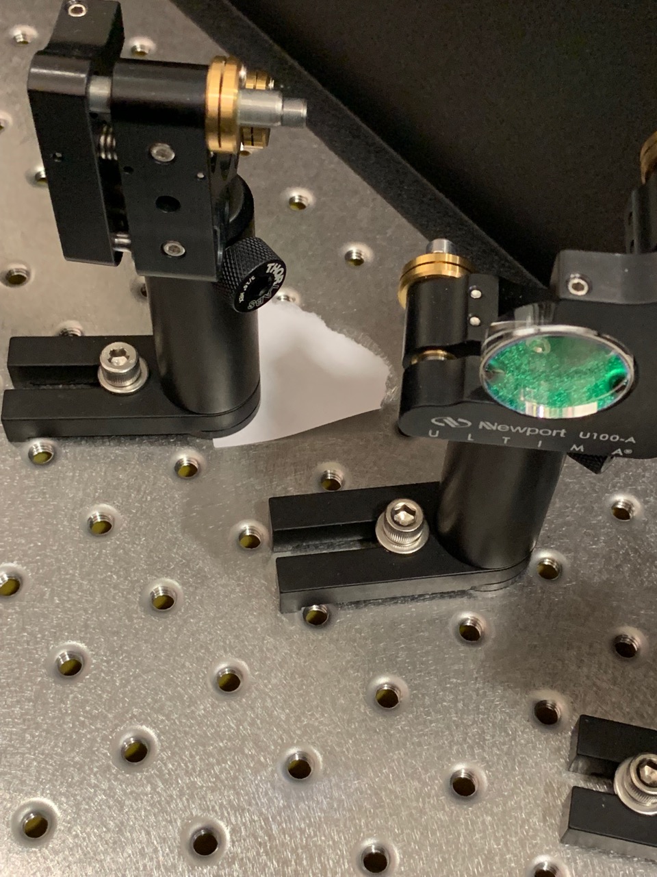
Either there are issues with this particular mount, or this type of mount has design flaws. Or maybe it is the way we are suing them (over-tightening?). The third attached image shows that a piece of paper could be slid under the back of the base, indicating that the base is only contacting the breadboard one edge. I've discussed this briefly with Stephen Appert and we plan to investigate this flaw and possible solutions with the SYS group.
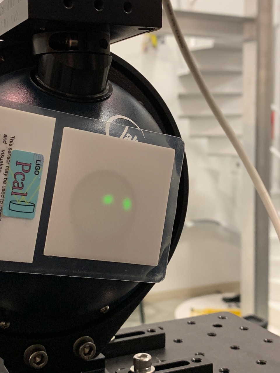
We adjusted the beamsplitter to re-center the Outer Beam on the Rx power sensor aperture (see fifth image below, with both beam incident on the Rx power sensor aperture), fine-tuned the alignment onto the Far Outer Beam iris in the Tx module, then proceeded with a standard end station Pcal calibration measurement suite. The scanned log of the measurements is in the attached .pdf file.
Current results are in good agreement (with a few hundredths of a percent) with the mean of the previous Yend measurements.
| Sensor | Dec. 13 | Jan. 15 | Jan. 29 | Feb. 26 | Feb 26 / mean of prev. meas. |
|---|---|---|---|---|---|
| Tx (V/V) | -0.480810 | -0.480448 | -0.480937 | -0.480805 | 1.00015 |
| Rx (V/V) | -0.715832 | -0.715410 | -0.716157 | -0.715337 |
1.00028 |
As mentioned in T1300659 the ID of this rocking transmitter module post holder is:
The receiver module also utilizes this type of post holder, but in 2" height (p/n UPH2).
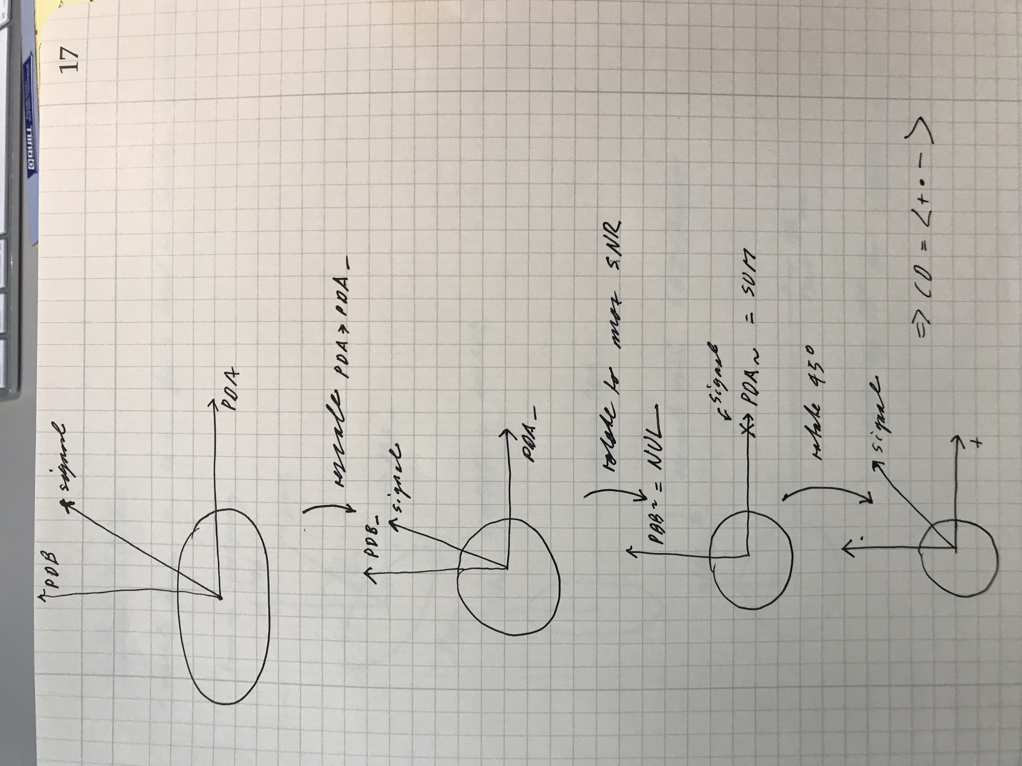
This is a follow-up to alog 45734.
It answers the question of how to set the DCPD input matrix, with some more background.
Basics:
- We can measure two numbers (ratios):
g = PD_A/PD_B coherent signal amplitude ratio (best done by looking at the PD_A/PD_B transfer function at low frequencies)
h = PD_A/PD_B shot noise signal amplitude ratio (by matching the amplitude spectra - a transfer function does not work here)
- These are directly related to the OMC BS splitting ratio 'bA/bB' and the sensing chain gain ratio between the two photo diodes, gA/gB via
g = gA/gB * bA/bB
h = gA/gB * sqrt(bA/bB)
in particular we have g/h = sqrt(bA/bB)
- I can write the photodiode signals as
PDA = g * s + h * nA
PDB = s + nB
or, rescaling PDA to match the shot noise level of PDB, PDA_ = PDA/h
PDA_ = g/h * s + nA
PDB_ = s + nB
Here s is the signal as seen by PDB, and nA and nB are realizations of shot noise, scaled such that <nA^2>=<nB^2> (i.e. same power spectral density).
They are independent, i.e. <nA*nB>=0.
- Since the two shot noise levels are equal and uncorrelated, we can now rotate the signal by any angle theta to maximize our readout SNR:
/ PDA~ \ / PDA_ \
| | = R | |
\ PDB~ / \ PDA_ /
or in vector notation:
x~ = R x_
Note that the shot noise levels in PDA~ and PDB~ remain uncorrelated and equal during this rotation.
Here R is the recular rotation matrix:
/ cos(theta) sin(theta) \
R = | |
\-sin(theta) cos(theta) /
- If we rotate all the signal into PDA~, PDA~ becomes DCPD_SUM, and PDB~ becomes DCPD_NULL. This is achieved for
theta = atan(h/g) = atan(sqrt(bB/bA))
- The matrix proposed in alog 45734 did exactly that, with
i) an additonal sign change for DCPD_NULL, i.e. DCPD_NULL = - PDA~
ii) rescaling the overall matrix gain to some aribitrary, traditional value set by A+B=2 (see alog 45734 for details, also the attached MATLAB file).
To be explicit, the alog 45734 matrix M is equal to
M = gain * diag([1,-1]) * R * diag([1/h,-1]);
- The cross-power CP between the two photodiodes can be calculated for any rotation angle theta:
With
/ 0 1/2 \
C = | |
\ 1/2 0 /
we get
CP = < PDA~ * PDB~ > = < transpose(x~) C x~ = transpose(x_) transpose(R) C R x_ >
or
/ -sin(2*theta) cos(2*theta) \
CP = < 1/2 transpose(x_) | | x >
\ cos(2*theta) sin(2*theta) /
or
CP = cos(2*theta) < PDA_ * PDB_ > + sin(2*theta)/2 * ( < PDB_^2 > - < PDA_^2 > )
There are now two ways to choose the theta for this cross-power calculations:
A) Stay in the original PDA_-PDB_ basis: theta=0deg
B) Optimize the SNR ratio in the cross-power: theta = theta_SUMNUL - 45deg
A) Guarantees that the cross-power measurement is independent of the measured gain-scaling - at least at high frequencies
(Low frequencies require loop gain corrections anyway).
B) This introduces a slight sensitivity to the measured shot noise ratio in the two diodes (sin(2*theta)/2 term).
But since the loop gain correction needs to be done in the SUM_NULL basis anyway, that is a bit of a mute point,
and should not matter for realistic OMC BS splitting ratios.
*****************************************************************
Bottom line:
If we follow the procedure from alog 45734, the cross-power estimator should work as advertised.
Practical suggestion:
The process will be less mysterious if we put the shot-noise-matching gain '1/h' up front in the PDA filter modules.
Then we can use a pure rotation matrix for the PDA_PDB to SUM_NULL matrix M.
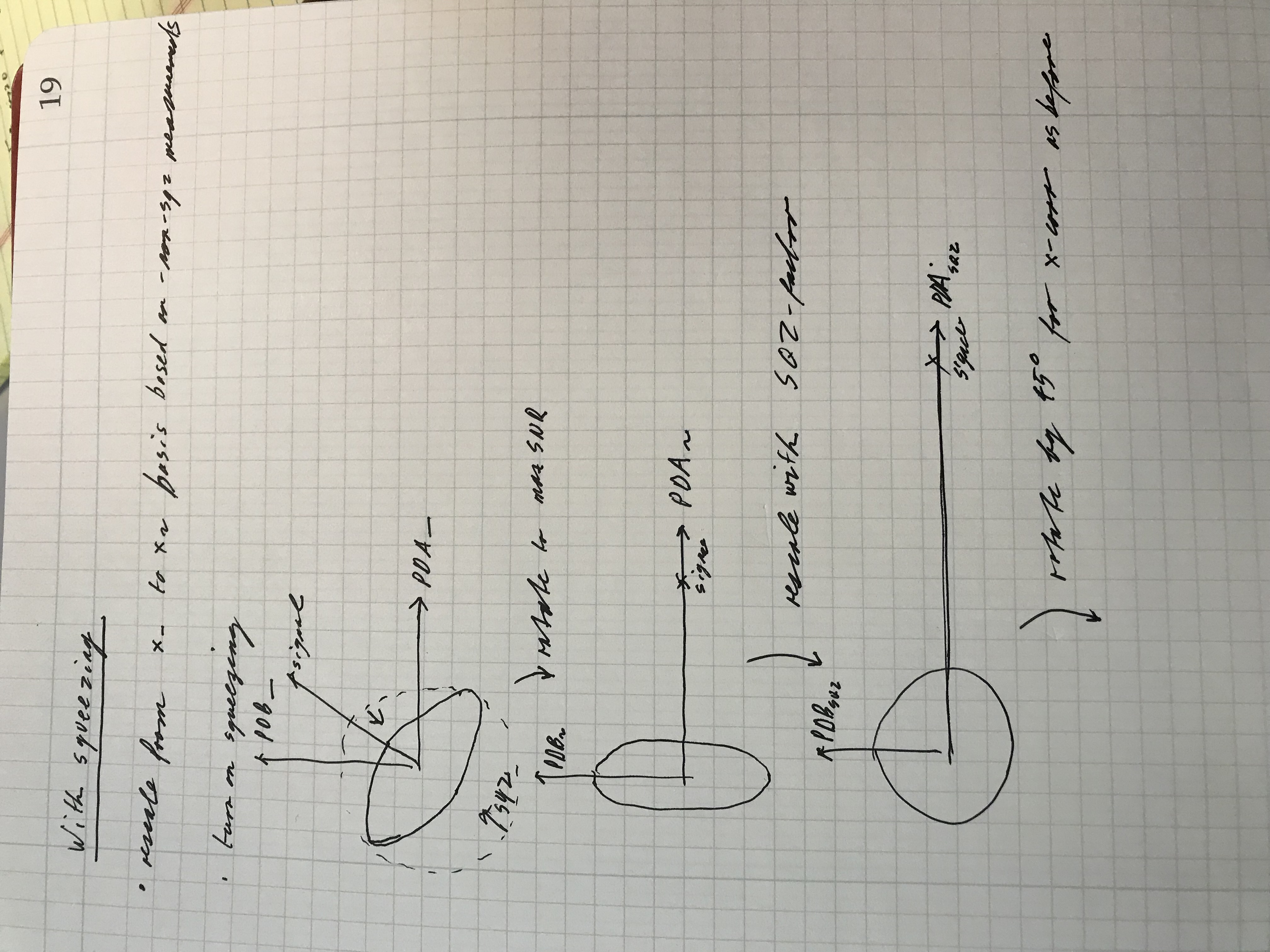
Attached are two hand-drawn illustrations.
1) Illustrations for the discussion above
2) What would change form 1 when we use squeezing. If we know the squeeze factor the cross-correlator can be made to work in principle. But precise knowledge of the squeeze factor is needed.
Also attached is the MATLAB file for calculating the input matrix.
16:44UTC Diag Reset cleared it
Richard, Dave:
we are having problems with digital camera-16 and others on h1digivideo1. This server was rebooted at 08:26 to clear the errors.
reboot fixed the problem.
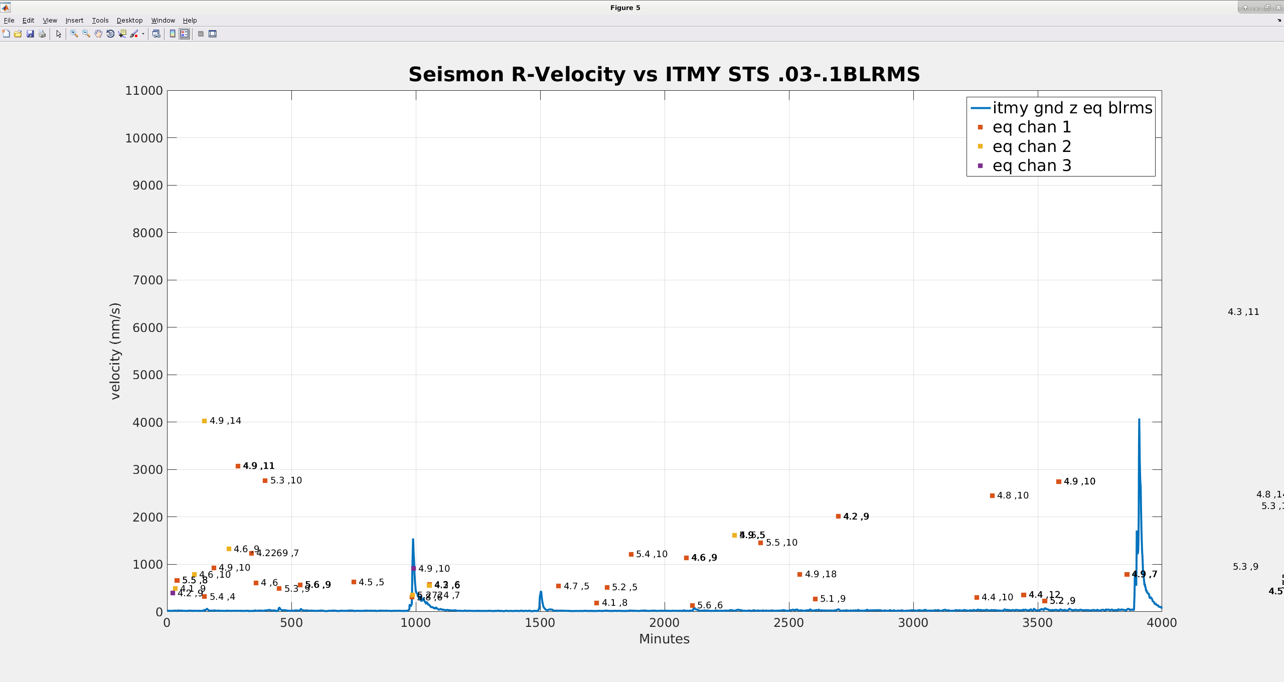
I actually started this a long time ago, but got swamped with other work and buried by snow. Our seismon code does not seem to give an accurate prediction of ground velocities. Attached plot compares the timeseries .03-.1hz rms ground velocity measured by the ITMY STS in Z (solid blue line) and the seismon predicted ground velocities for 5000 minutes of data from this month. Each dot represents the predicted velocity and arrival time for each earthquake seismon found over this time period (seismon can give up to five active predictions, eq chan 1,2 & 3 are the first 3 predictions, typically the "live" ones if seismon has given us early warning). The numbers by each prediction point are the magnitude and distance in 1000km of the earthquake (so 5.8, 10 is a 5.8 magnitude earthquake 10,000 km away). The earthquake at 4000 minutes actually has a arrival time prediction , but the predicted velocity is up around 60 micron/s, which made the rest of the plot hard to see, so I cut it off.
I would expect that if seismon was accurately predicting ground velocities, the dots would follow the blue line in some way. If there is a systematic relationship between the dots and the line, I don't see it.
The good new is that for other time periods when there were large earthquakes, seismon usually gave us early warning, which is the primary goal. But it would help deciding what the response to a notification should be if we could get a believable prediction of the velocities.
This aLOG has earned the inaugural LHO Paper Plate Award. "This award goes to Jim Warner for Most "meta" aLOG in 2019 (LHO aLOG 47200)." The award has been endorsed by our operations manager, in the presence of Jim and a witness -- our site safety officer. Jim has received the award in person, smiled, and sends his "thank you"s. References on what a "Paper Plate Award" is for those who've not heard of it: - The best definition (but by example) I could find - Some other examples of how they're used in practice. - A story of the award's power from SportsEngine - An anecdote from the .
For posterity -- the LHO Paper Plate Award was given for the first iteration of this aLOG that was posted -- it had only contained a title and an attached screenshot of the aLOG draft. Jim was aware of the issue within the 24 hour "set in stone" editing time limit, so he's since updated the aLOG to have its originally intended content and completeness.
TITLE: 03/01 Day Shift: 16:00-00:00 UTC (08:00-16:00 PST), all times posted in UTC
STATE of H1: Commissioning
OUTGOING OPERATOR: None
CURRENT ENVIRONMENT:
Wind: 6mph Gusts, 4mph 5min avg
Primary useism: 0.03 μm/s
Secondary useism: 0.39 μm/s
QUICK SUMMARY: ROn our wy back up to NLN, Jenne ready to start commissioning as soo as we are back to low noise.
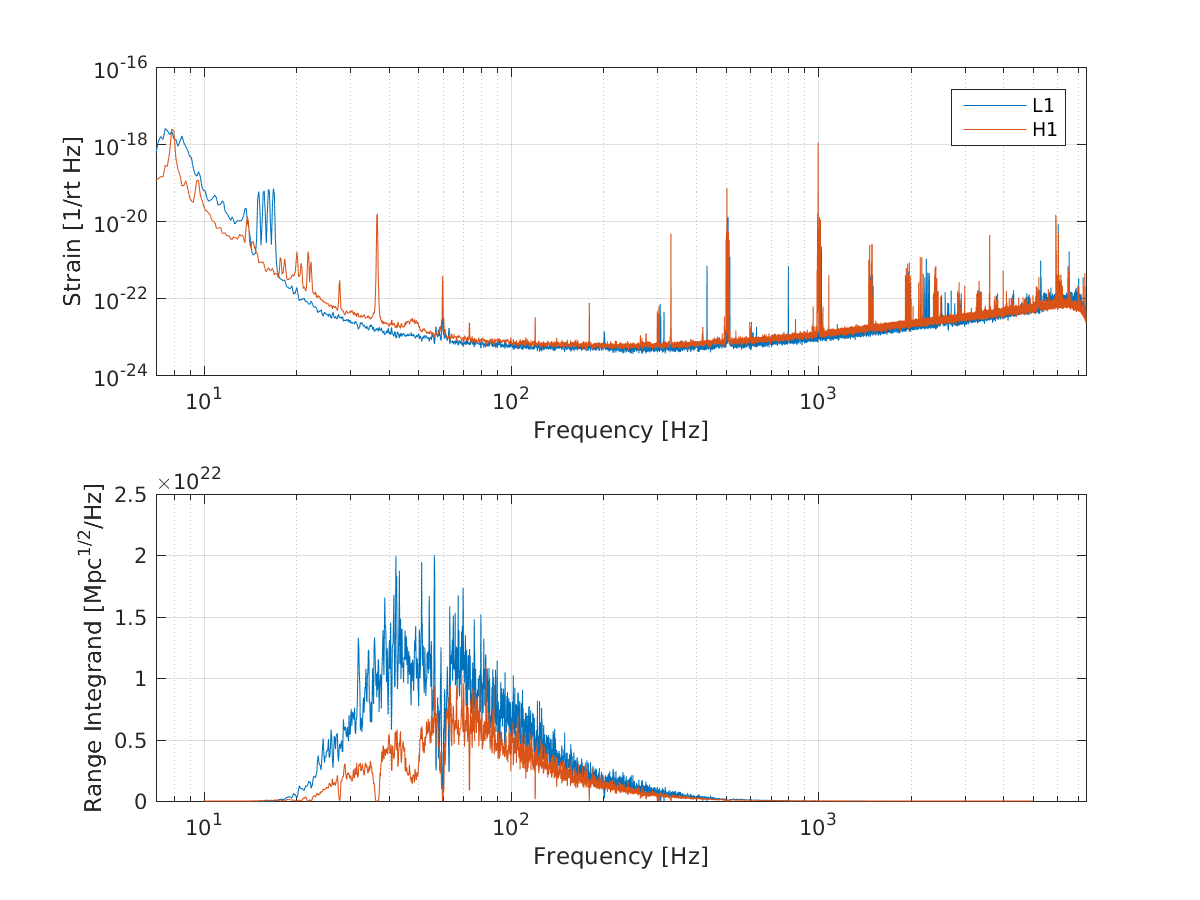
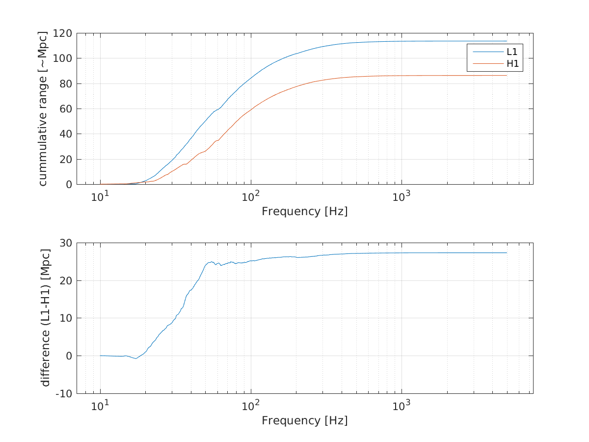
I had a quick look at the range integrand tonight, at a time last night when both L1 and H1 had fairly good ranges according to sensmon (L1 was nearly 140Mpc, H1 was nearly 100Mpc). I used some code that gives an approximation of the range integrand, the absolute scale is wrong so that the total ranges I calculate are underestimated. The first attachment shows the sensitivity of L1 compared to H1 and in the lower plot the range integrand. The second plot shows the cumulative range for both interferometers and the difference.
From the second attachment you can see that we can gain ~20 Mpc by improving our noise from 40-20Hz. In the first attachment you can see that the shoulders on the 60Hz lines are costing us.
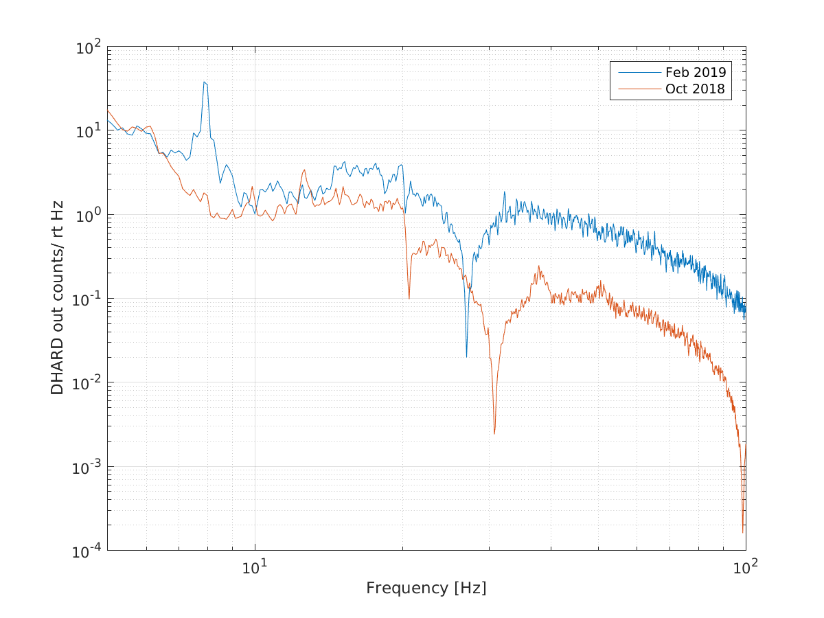
Last night I posted an incomplete ASC noise budget that shows that DHARD P+Y are both making large contributions to the DARM noise in this band. 47176 Since this is the band that we need to improve I started to look at why this noise is worse. The third attachment shows a comparison of the DHARD P control signals from October 25th and last night, you can see that the control signal is about a factor of 10 larger in the band where it limits DARM than it was in October. The RPC output is not included in this plot or in the noise budget that I posted last night, but it is too small to matter. The 4th attachment shows a comparison of the filters we were using in October; in addition to the filter change we are now using a gain of -42 instead of -30 in October.
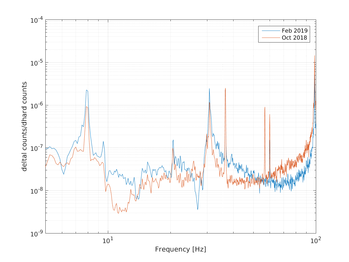
The last attachment shows a comparison of the coupling (DARM uncalibrated ASD/DHARD out ASD), you can see that the coupling hasn't changed much since October and most of the difference in noise is due to the loop shaping. We have had many problems with the stability of the DHARD loop, which have been written about in several alogs, which is why the gain of this loop has increased, and the cut offs have become less aggressive. It has been a while since we measured DHARD, so we were planning to try to get a good measurement before the earthquake hit.
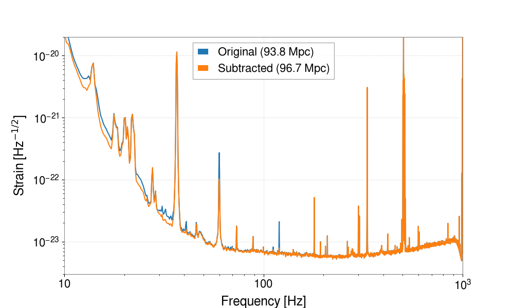
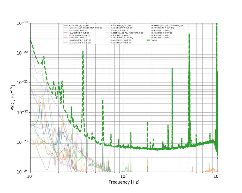
I ran a linear noise subtraction (T1800552T1800552) using all ASC signals, MICH/SRCL/PRCL and ISS signals. I used 600 seconds starting from GPS 1235390418. The first plot shows that the noise subtraction is effective at low frequencies, and improves the range from 93.8 MPc to 96.7 MPc (estimated using gwpy and GDS-CALIB_STRAIN). So 2.9 MPc more, no quite O(10 MPc) as Sheila expected.
The second plot shows the main contributions.
J. Kissel, G. Mansell, C. Cahillane, S. Dwyer While trying to solve a few ASC problems and considering running initial alignment, we got slammed by a 7+ mag earthquake from Peru around 2019-03-01 09:11 UTC (01:11a PT local). We've hit the VERY LARGE EQ button (turns all sensor correct OFF, and requests all platforms to ISI_DAMPED_HEPI_OFFLINE). All of the test mass BSC ISIs tripped (but not the BS, for some reason), and only TMSY suspension tripped. We've reset all watchdogs, but are staying in this damped state for bit while the EQ roles through...
We had some trouble with locking due to ASC this afternoon.
We had some locklosses when engaging ASC. We have been engaging all the QPD and WFS loops first, then adding the dithers after, but we have found that sometimes engaging all the loops other than the dithers brings the build ups down, until the dither loops are engaged. This afternoon Georgia and Jenne moved the DOF3 dither loop (ITMY-> PRM) engagement so that it comes on at the same time as the WFS loops. This seems to be working. I also increased the tolerance on some of the convergence checkers in the engage_ASC state, which has been taking ~10 minutes. It looks like there are some places where we are increasing gains after integrators in these states, which is why we need the long waits for offloading, but we could avoid this by moving the gains upstream of the intergrator.
We also lost lock twice in LOWNOISE ASC tonight, there is a large transient when we reduce the dither amplitudes and increase the dither loop gains. Georgia and I went through the dither loops and set them all up to be engaged with their final loops gains, so that we will no longer be increasing the gains of the loops in this state.
Jeff and I also had one lockloss where POP90 became large in final stage of the CARM offset reduction, which is something that I have seen happen before.
Georgia found that at 2W we can get higher POP18 build ups and lower POP90 with an offset in the SRC2Y SRC1Y loop.
Twice in a row we've lost lock during ENGAGE_ASC_FOR_FULL_IFO with the PRM ADS loop coming on at the same time. It seems mostly like a SRC problem - I could move SRM and get POP 90 down, and POP 18 and PRG up, but I'm just fighting the ASC, and if I stop clicking, the ASC pulls the SRM back to a bad place.
TJ and Ed are doing a wfsreliefpast to the time of my last lock this morning, which was right after I did an initial alignment.
We never offload our full IFO ASC to the suspensions because we have historically been concerned about wire heating, but perhaps with all the new baffling, we could offload our ASC (as LLO is talking about doing LLO-43581) after the SOFT loops have engaged and converged, before we increase power beyond 2W.
J. Kissel After months of at-best "really annoying" and at-worst "progress crippling" woes with svn 1.6 version checkout of the calibration group's SVN repository, on the CDS workstations'(i.e. the /ligo/svncommon/CalSVN/ folder of ... "the boot machine" or "file server" I think they call it ... I think), I bit the bullet and reconciled (checked in) everything local, and then hit "svn upgrade" at the root level of the check out. jeffrey.kissel@zotws3:/ligo/svncommon/CalSVN/aligocalibration$ svn --version svn, version 1.9.5 (r1770682) compiled Jul 21 2018, 02:35:40 on x86_64-pc-linux-gnu Copyright (C) 2016 The Apache Software Foundation. Now we no longer have to type "svn1.6" in the repo, and we can make svn calls from scripts again. You're welcome Evan! #DeeeeHardWoofs
J. Kissel, S. Dwyer,
After Sheila fixed a few hiccups in the NLN_CAL_MEAS state's return to NOMINAL_LOW_NOISE in the ISC_LOCK guardian, I was able to gather all measurements necessary for updating the actuation function of the calibration. I was tuning the amplitude in sensing function's DARM OLG sweep to get better coherence between 5 - 20 Hz (to resolve detuning), aborted the measurement and we lost lock [it was a swept sine, and yes, it had a 3 sec ramp down time. I was actively watching the ASDs of ETMX digital requests to the DAC and we were no where close to saturating].
Anyways -- analysis to come, but the data lives here:
/ligo/svncommon/CalSVN/aligocalibration/trunk/Runs/O3/H1/Measurements/FullIFOActuationTFs/
2019-03-01_H1SUSETMX_L1_iEXC2DARM_25min.xml
2019-03-01_H1SUSETMX_L1_PCAL2DARM_8min.xml
2019-03-01_H1SUSETMX_L2_iEXC2DARM_17min.xml
2019-03-01_H1SUSETMX_L2_PCAL2DARM_8min.xml
2019-03-01_H1SUSETMX_L3_iEXC2DARM_8min.xml
2019-03-01_H1SUSETMX_L3_PCAL2DARM_8min.xml
Note that during these measurements, one *has* to turn of the Alignment Dither Loop system (namely DOFs 3 4 and 5), which controls the drift of the Y Arm (roughly equivalent to the SOFT DOF). With the loops OFF, the alignment does drift slowly, on a ~20 minute time-scale. As such, given the length of my measurements, I went back from NLN_CAL_MEAS to NOMINAL_LOW_NOISE in between clusters of measurements and waited there for the ADS error signals to steer back towards zero (which takes about 5 minutes), then switched back to NLN_CAL_MEAS and resumed measurements.
And although the data is meaningless, the amplitudes and frequency vectors in the sensing function templates
/ligo/svncommon/CalSVN/aligocalibration/trunk/Runs/O3/H1/Measurements/FullIFOSensingTFs/
2019-03-01_H1DARM_OLGTF_5to1100Hz_20min.xml
2019-03-01_H1_PCAL2DARM_TF_5t1100Hz_8min.xml
should be used for future measurements.
If you need it, my template for watching the ESD and Coil Driver DAC requests during measurement lives here
/ligo/home/jeffrey.kissel/Templates/DTT
H1ETMX_ActuatorSaturations.xml
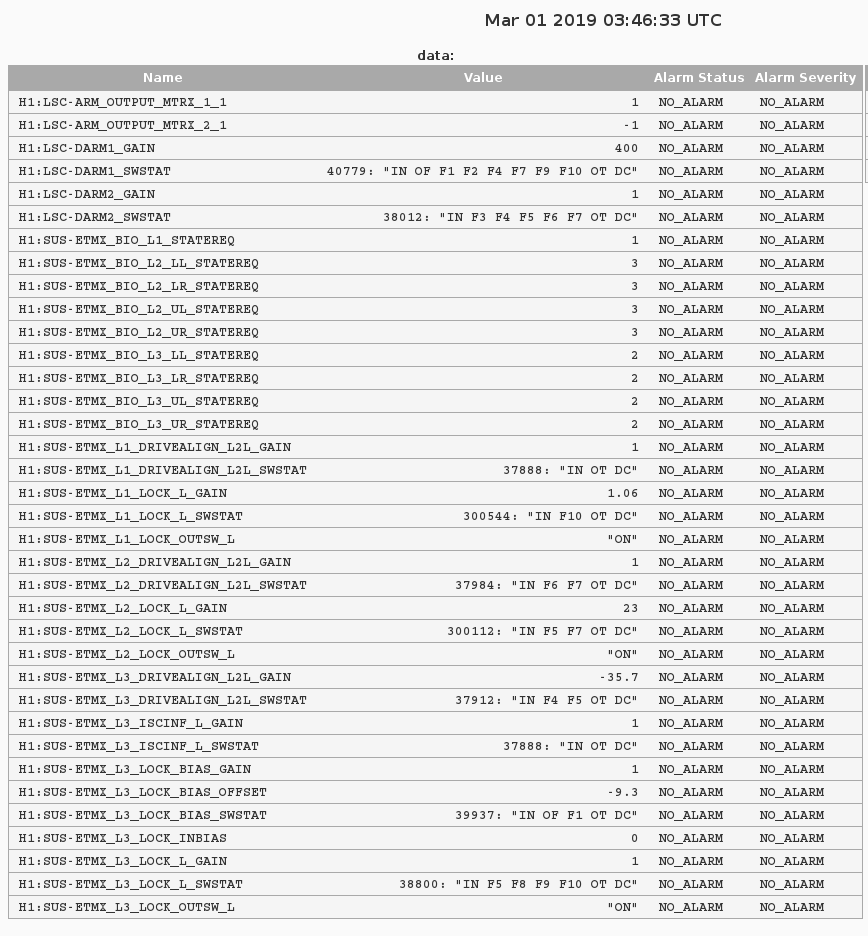
Here're the DARM loop settings for the actuator during the time of this measurement.
The filter file for ETMX is also attached.
It's from the filter archive.
There are several files around the time of the measurement (Data taken between 2019-03-01 02:55:17 [1235444135] and 2019-03-01 04:33:58 UTC [1235450056]),
/opt/rtcds/lho/h1/chans/filter_archive/h1susetmx/
H1SUSETMX_1235362558.txt (translated -- Feb 28 2019 04:15:40 UTC)
H1SUSETMX_1235500682.txt (translated -- Mar 01 2019 18:37:44 UTC)
So the data should be covered by the Feb 28th filter file. That file has been copied over to the CAL group's filter archive, for easy access,
/ligo/svncommon/CalSVN/aligocalibration/trunk/Common/H1CalFilterArchive/h1susetmx/
H1SUSETMX_1235362558.txt
While TJ was doing initial alignment today, after the green arms had converged, I ensured that PR3 was in the new position that we've been using the last few days, and aligned the beatnotes on ISCT1. I only got COMM to about -3dBm (it used to be more like +6 dBm), but since that's enough, I didn't take a lot of time to try to eek out more. Diff is now about -6 dBm, rather than the previous -12 dBm.
Also today, I put the turn-off of the ADS loops into NLN_CAL_MEAS, since I killed the lock earlier today by forgetting to turn off those loops before doing some calibration actuator measurements (and we almost killed the lock again by doing some noise budget injections). So, now if we're going to do any injections that might drown out the ADS dither lines, we should go to NLN_CAL_MEAS, and it'll take care of the ADS.
Also, also, I flipped the demod phases of 3/6 of the ADS loops, so that all of the ADS DOF gains are positive. This has been accepted in SDF and put into the guardian.
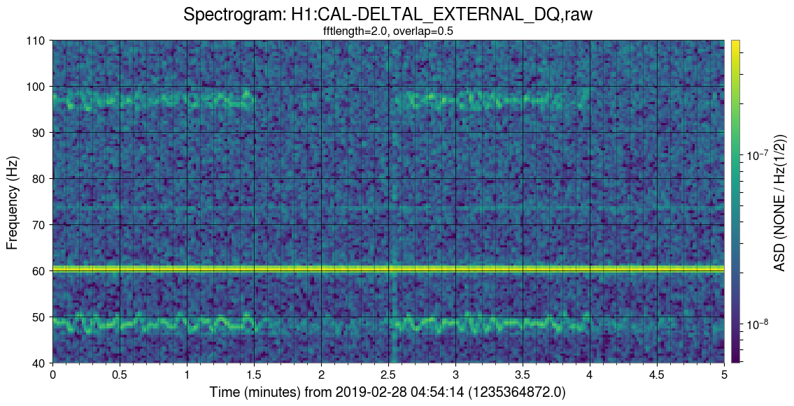
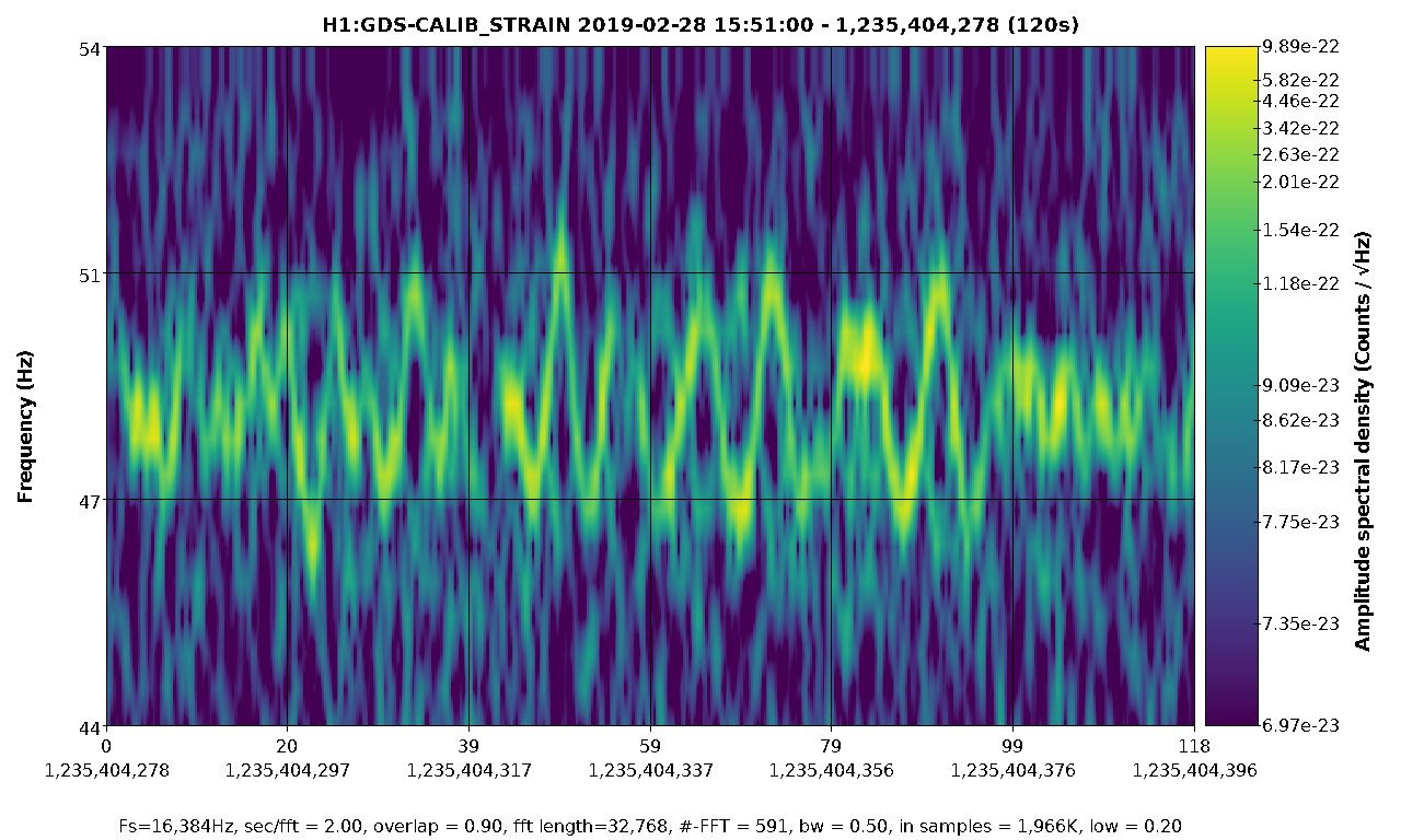
There is a broad noise peak at 48 Hz and its harmonic (96 Hz) that comes and goes in DARM. We do not know the cause, and I am posting this in hopes that DetChar can look into it. The attached pdf shows the DARM spectrum over ~10 minutes, but the spectrogram shows that the broad spectral feature is actually a narrower line that is wandering in frequency by several Hertz, at a time scale of 5-10 seconds. We know that these peaks can appear with or without the squeezer injection.

Hi Peter, this is what we once found about 48Hz. We can check tomorrow if this is still the situation.
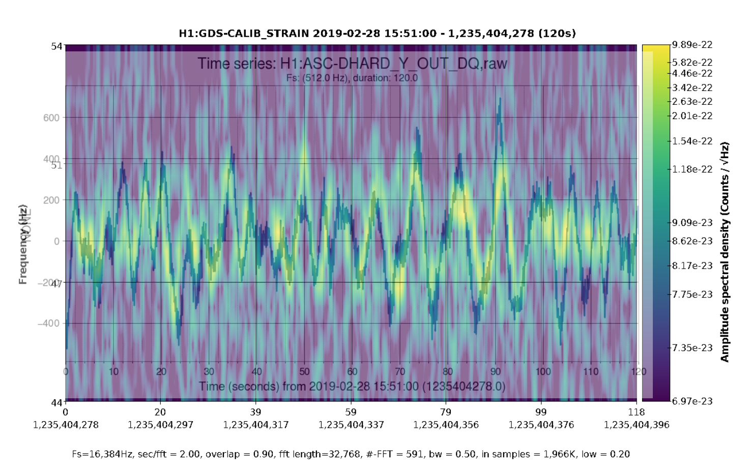
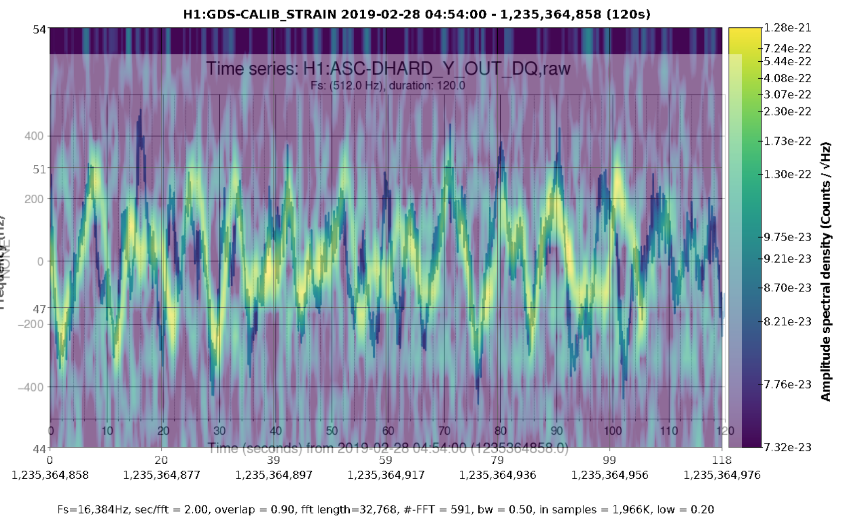
The tank motion mechanism reported back then by Jeff doesn’t seem to be related to the current 48 Hz and 96Hz frequency-modulated lines. The frequency track of the fast moving ~48 Hz line resembles alignment signals such as DHARD Y but we haven’t exhaustively checked other signals. We also don’t have a good clue for the origin of the line and Bruco didn’t find coherence. Fig 1 shows a strong zoom of the line, it oscillates in frequency with a roughly 10s period and 4 HzPkPk amplitude. Fig 2 shows the same with DHARD Y overlayed. Fig 3 shows Peter’s time from above with DHARD Y.
I am wondering whether we can explain this as a whistle with untypically small frequency motion. Do we happen to have VCO and RF frequencies ~48Hz apart?
TITLE: 02/28 Day Shift: 16:00-00:00 UTC (08:00-16:00 PST), all times posted in UTC
STATE of H1: Commissioning
INCOMING OPERATOR: None
SHIFT SUMMARY: Commissioning work all day. Had to do an initial alignment on the last lock after we would lose lock at DHARD_WFS twice in a row.
LOG:
1600 Pfeifer crew and Kyle at MY
1625 Karen to MY
1741 Karen leaving MY
1835 Danny and Dan to LVEA SRM heater testing (WP#8052)
1847 Chandra, Kyle to MY to start some testing. Should not affect IFO.
1915 Danny and Dan out
1926 Nutsinee to LVEA to turn off equipment near SQZT6
1932 Nutsinee out
2130 Rich A to LVEA OMC rack
2134 Jenne to LVEA to adjust on ISCT1
21414 Dan, Sheila to LVEA to place black glass in OMC Trans camera
2200 Nutsinee to LVEA ISCT6 area
2213 Dan, Sheila out
2230 Jenne out
2232 Nutsinee out
2307 Rich A, Fil out
2310 Nutsinee out
2314 Rich A, Fil to LVEA to HAM6 racks
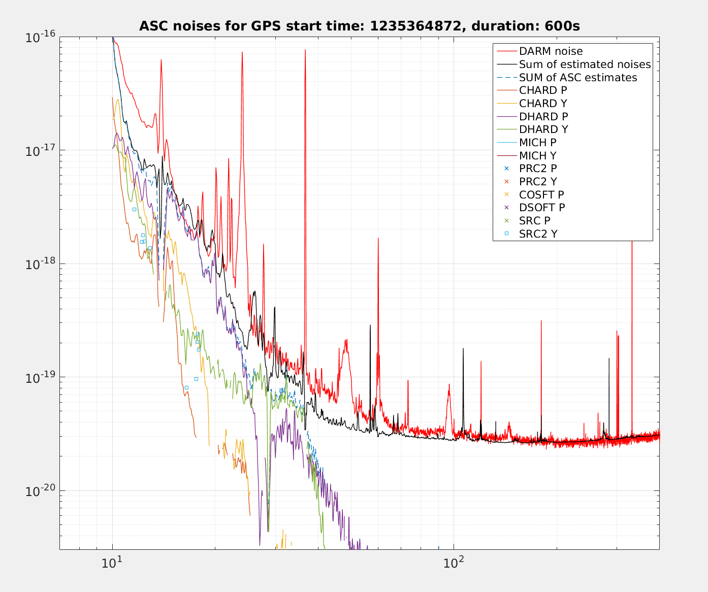
We got a few noise budget injections done in this lock before we lost lock. We will post a more complete noise budget once we have some more of the excitations done, a partial noise budget for the ASC noise contributions to DARM are attached.
The other interesting thing that we found was that MICH is only about a factor of 3 below DARM from 60-80Hz.
After we lost lock we needed to redo initial alignment, this might require realignment on ISCT1 since Jenne updated the initial alignment references for our new spot positions. 47168
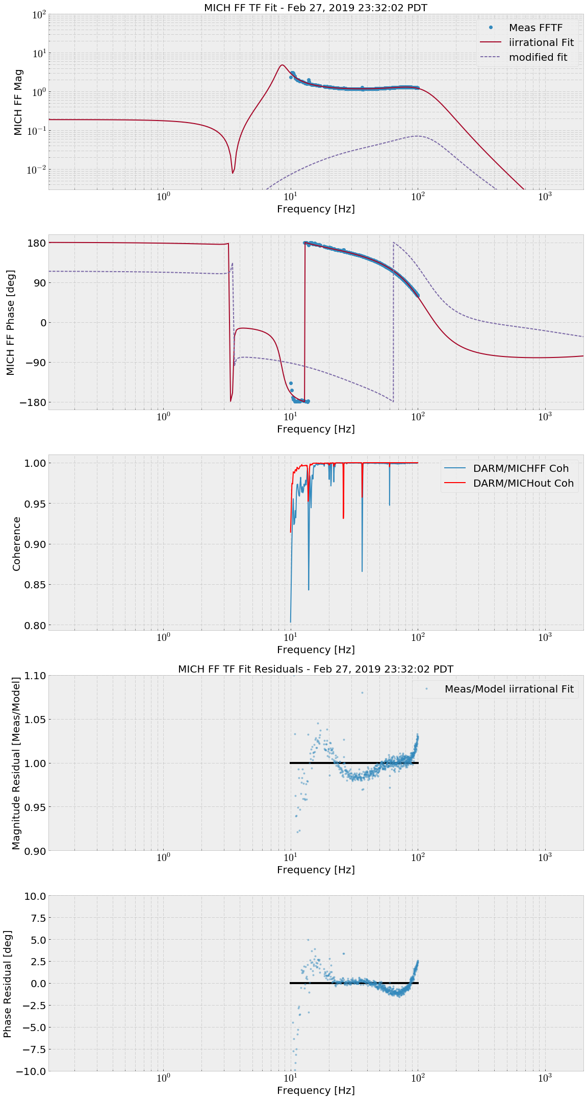
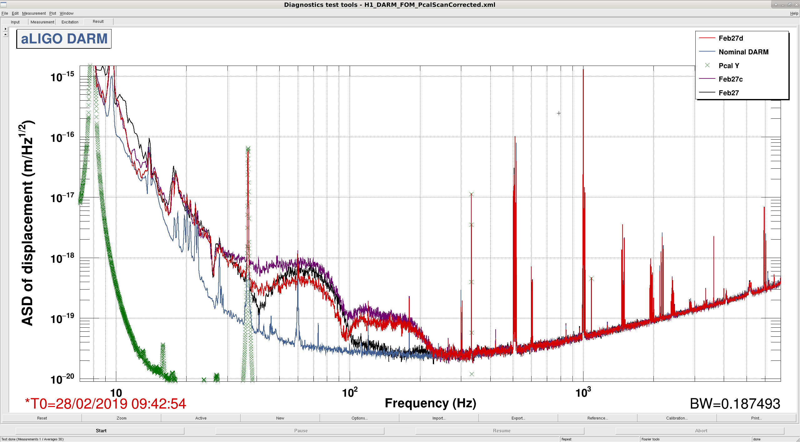
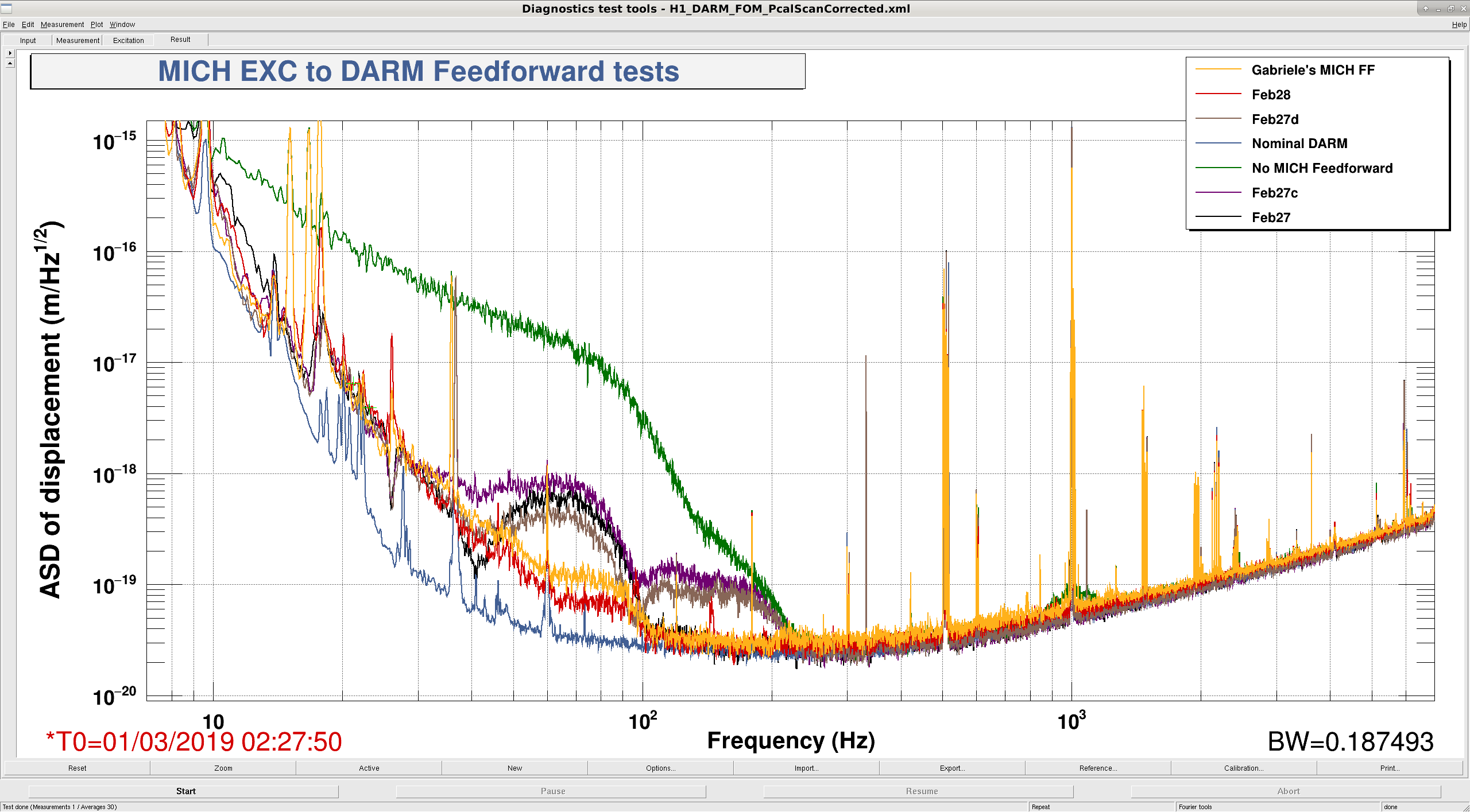
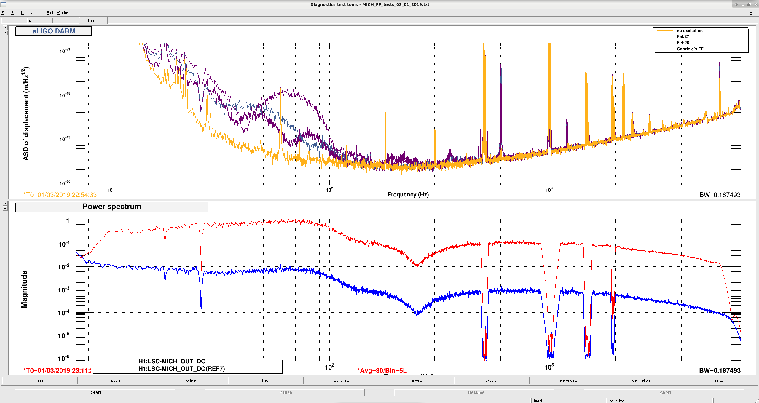
Redid the MICH FF and added another filter, Feb27c, to MICHFF FM8. Filter shown in the plot.Feel free to try it in the morning.Feb27c takes advantage of Danny's beamsplitter suspension resonance measurement. So far the best known feedforward is Feb27, in FM6. Feb27b gave worse noise than Feb27. Feb27c also gave worse noise than Feb27. The problem is the ~1 degree phase mismatch around 70 Hz in the MICHFF TF fit. Also some Feb27d was made and is sort of better at 70 Hz but is worse at 100 Hz. Leaving this one on for now.
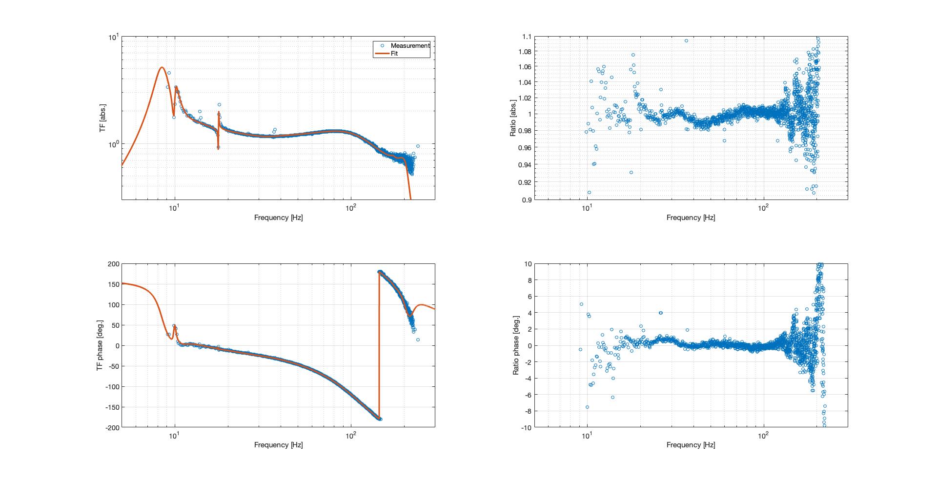
Here's a fit to the MICH FF which might have a better residual.
zpk([1030.2733+i*950.7986;1030.2733-i*950.7986;-94.6683+i*1386.0676;-94.6683-i*1386.0676;-38.9617+i*1095.7877;-38.9617-i*1095.7877;-47.1472+i*199.6596;-47.1472-i*199.6596;-15.1585;-0.025039+i*111.0189;-0.025039-i*111.0189;8.3412;-10.6324+i*71.093;-10.6324-i*71.093;-0.91023+i*62.1857;-0.91023-i*62.1857],[-5.0157+i*52.8173;-5.0157-i*52.8173;-1.2463+i*63.023;-1.2463-i*63.023;-13.5628+i*70.3543;-13.5628-i*70.3543;-0.0019152+i*111.1789;-0.0019152-i*111.1789;-48.6805+i*199.3746;-48.6805-i*199.3746;-335.845+i*587.6419;-335.845-i*587.6419;-37.2718+i*1094.6672;-37.2718-i*1094.6672;-88.2415+i*1288.8722;-88.2415-i*1288.8722],1)
Gain at 100 Hz: 1.24488138312429 (complex = -0.625528556960358 - 1.07631021665528i)
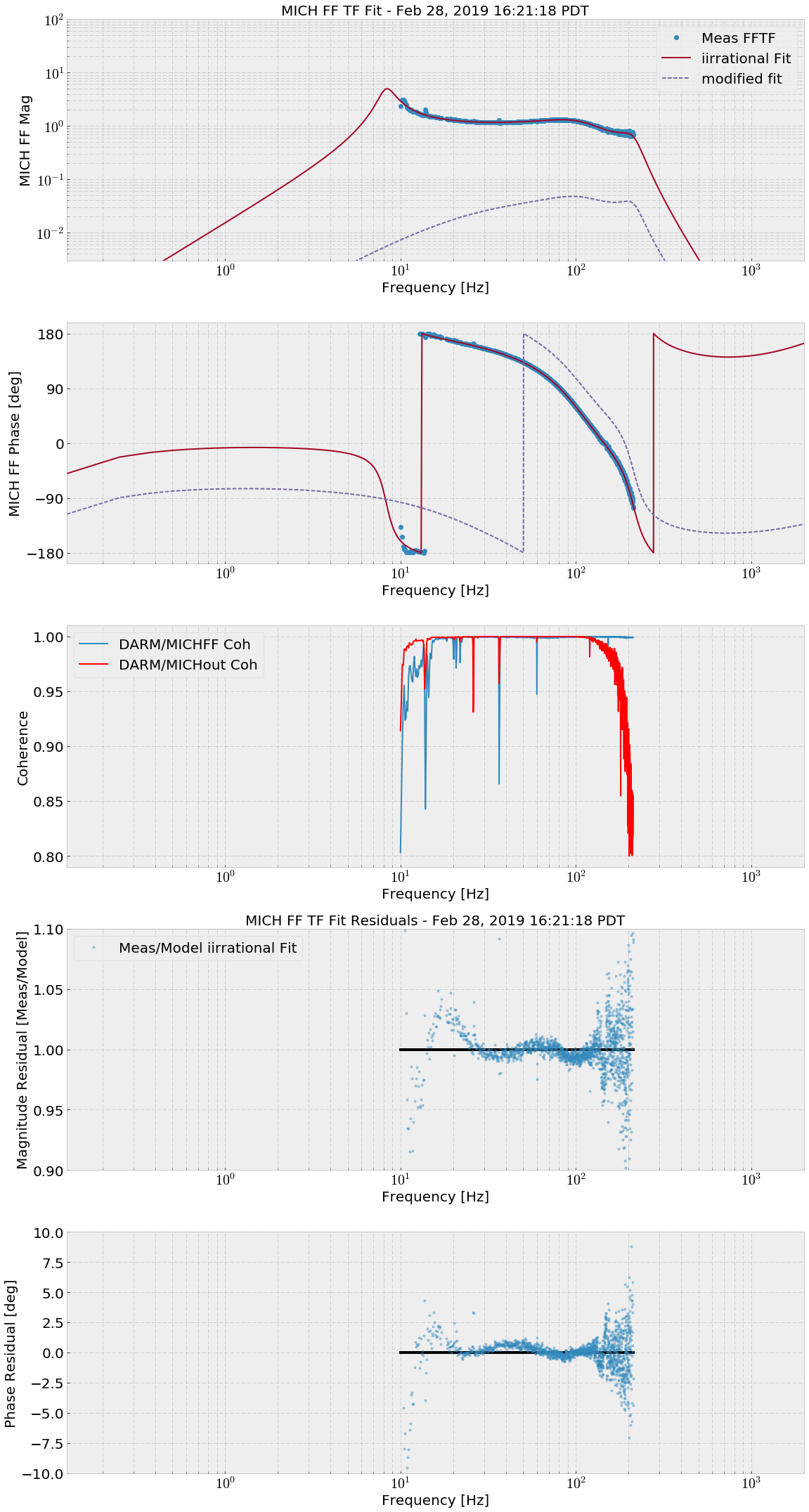
Tried Gabriele's filter in FM1 (copied below, scaled by -0.21415 gain, the one above does not agree with foton), as well as a new FF from me, called Feb28 in FM3 and plotted below.
Reran the injection test from last night. Both Gabriele's FF and Feb28 are much better than yesterday's MICH FF. These tests were done at the beginning of a lock, prior to complete thermalization taking place. Unclear if this matters to the FF quality.
Gabriele's FF
zpk([1030.2733+i*950.7986;1030.2733-i*950.7986;-94.6683+i*1386.0676;-94.6683-i*1386.0676;
-38.9617+i*1095.7877;-38.9617-i*1095.7877;-47.1472+i*199.6596;-47.1472-i*199.6596;-15.1585;
-0.025039+i*111.0189;-0.025039-i*111.0189;8.3412;-10.6324+i*71.093;-10.6324-i*71.093;
-0.91023+i*62.1857;-0.91023-i*62.1857],
[-5.0157+i*52.8173;-5.0157-i*52.8173;-1.2463+i*63.023;-1.2463-i*63.023;-13.5628+i*70.3543;
-13.5628-i*70.3543;-0.0019152+i*111.1789;-0.0019152-i*111.1789;-48.6805+i*199.3746;
-48.6805-i*199.3746;-335.845+i*587.6419;-335.845-i*587.6419;-37.2718+i*1094.6672;
-37.2718-i*1094.6672;-88.2415+i*1288.8722;-88.2415-i*1288.8722],
-0.21415
)
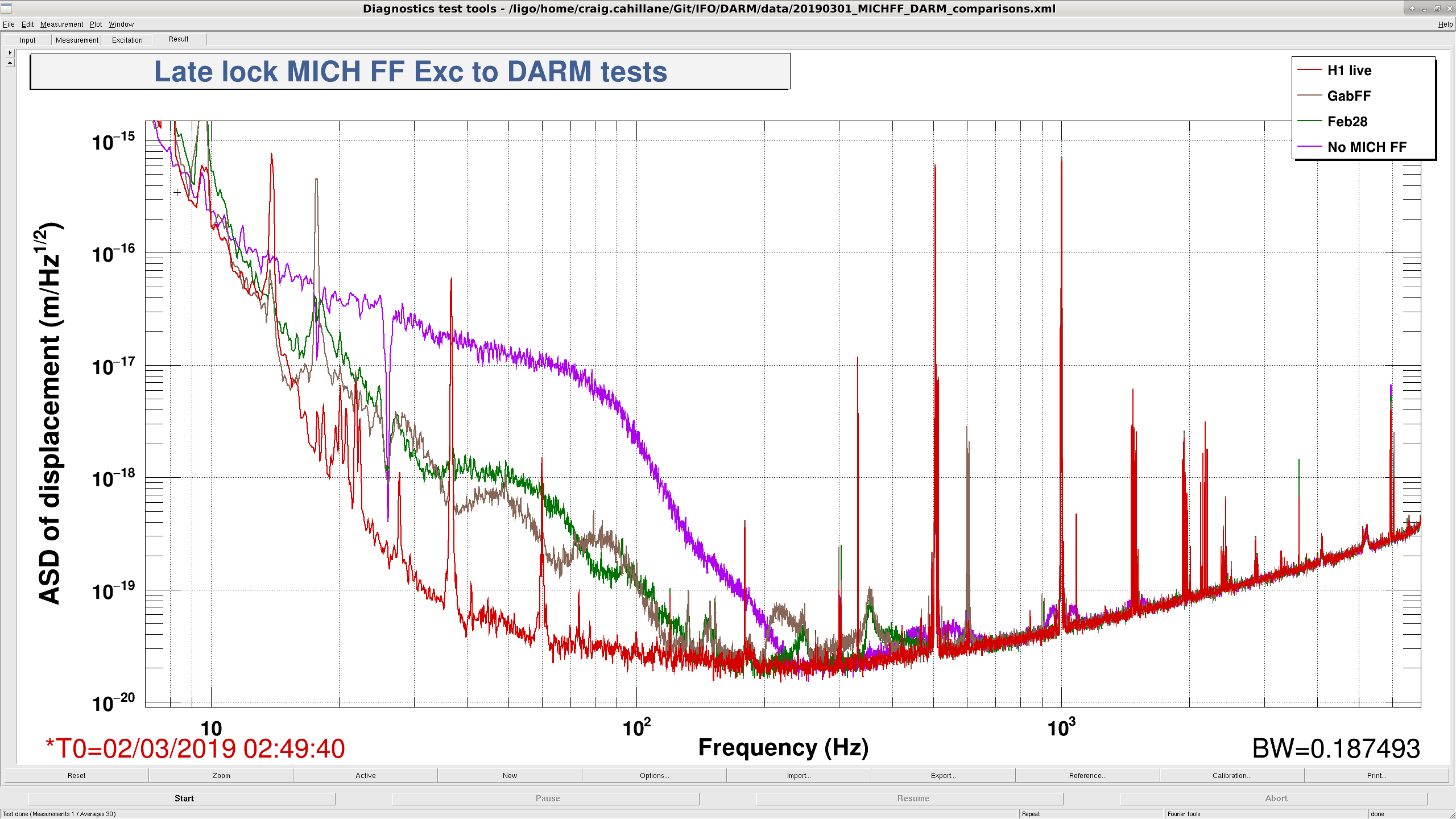
Measured MICH with the different feedforward filters after 3 hours into a lock. Both filters are better than Feb27. I switched out Feb27 with GabFF and used it to update MICH in the the noise budget.
We re-reran the MICH coupling later in the same lock. Danny said his test above had a slightly different excitation for each filter. Both GabFF and Feb28 are much worse. GabFF seems to be the better filter now. The overall frequency coupling is changed as well. It seems that further thermalization changed the feedforward even further, spoiling the linear noise cancellation. MICH to DARM length noise is projected to be only a factor of 3 below DARM with these levels of feedforward. We may need to make early/late lock MICHFF filters.