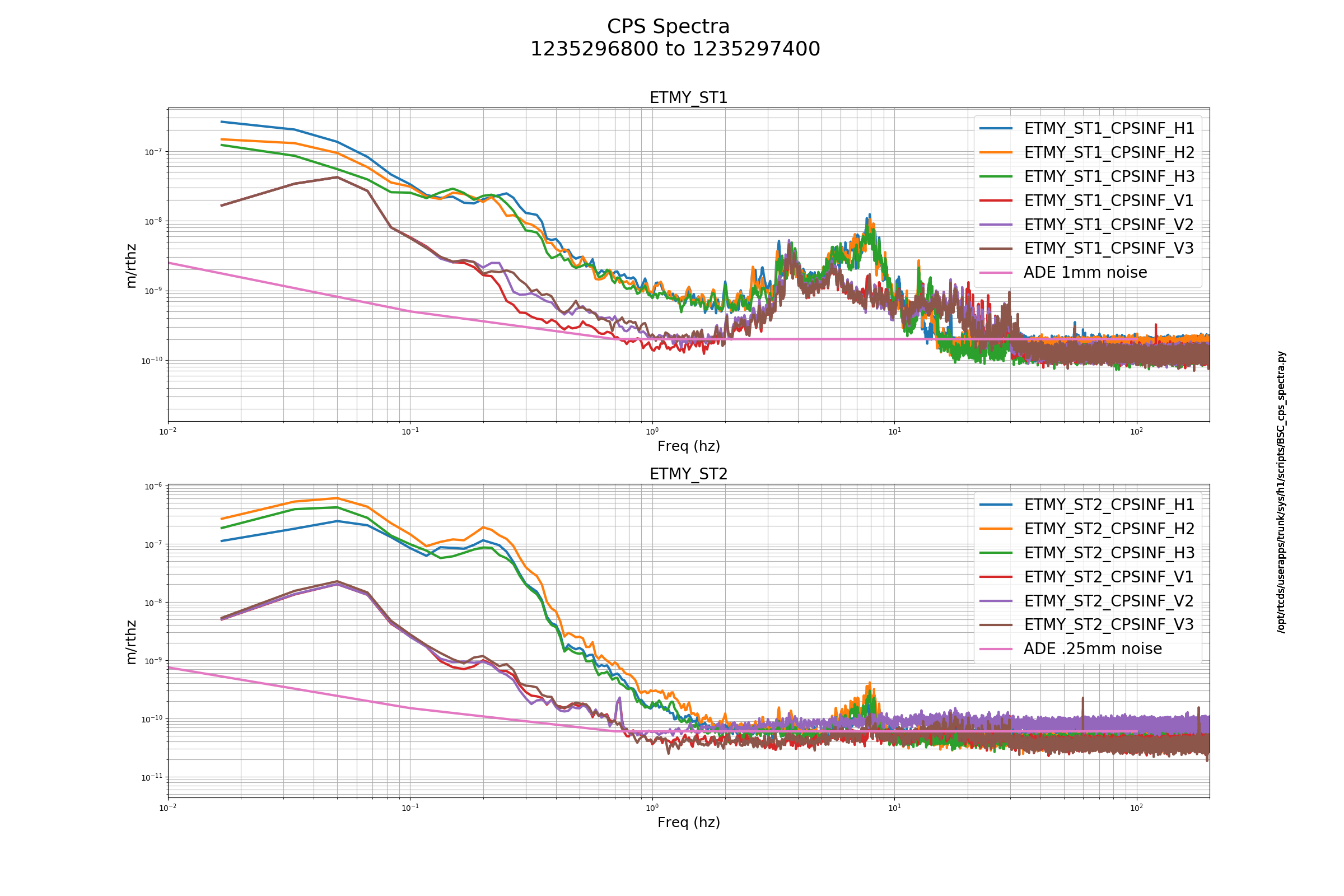
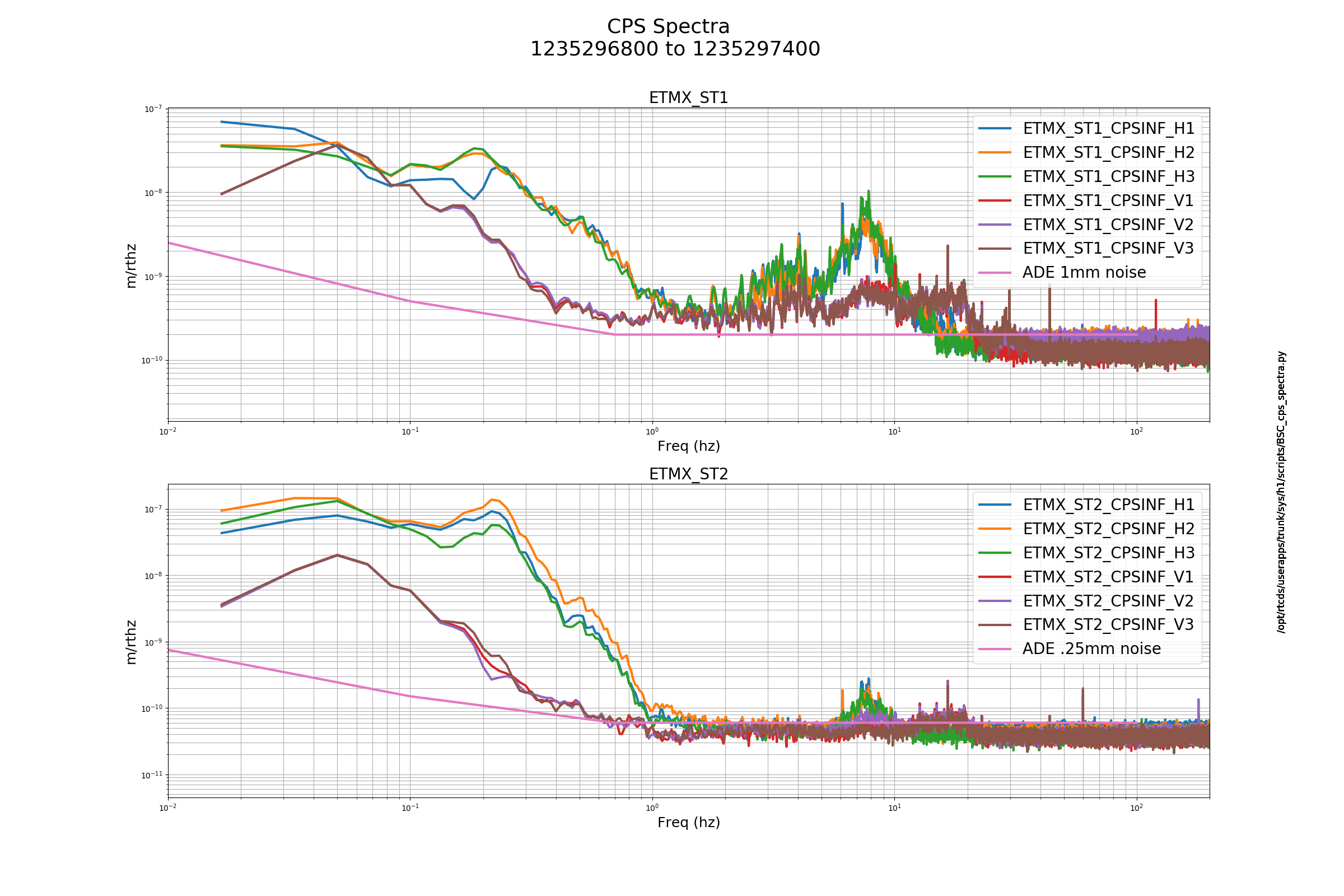
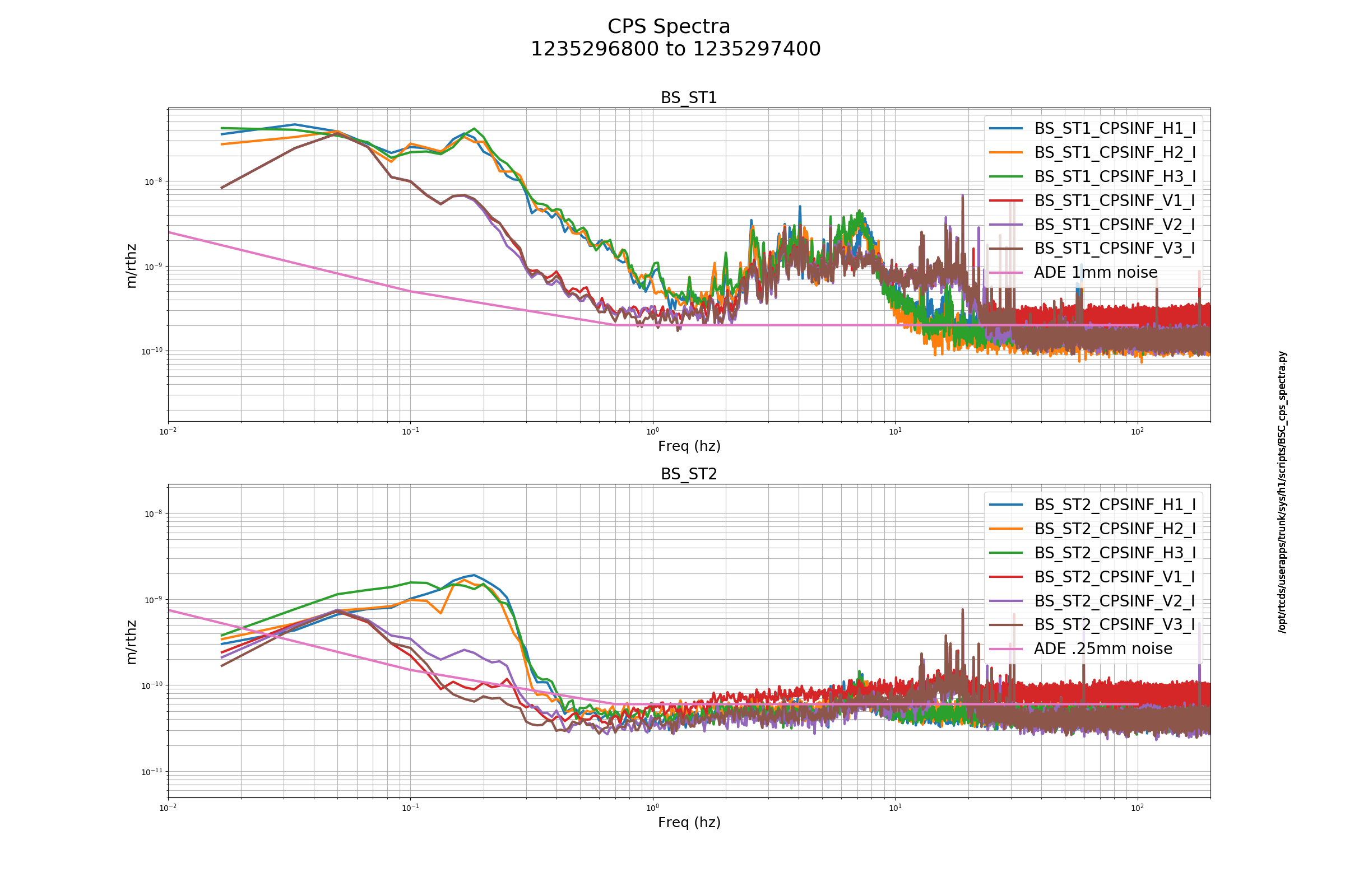
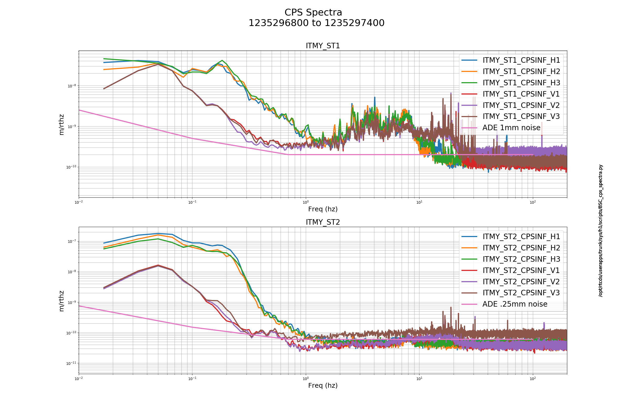
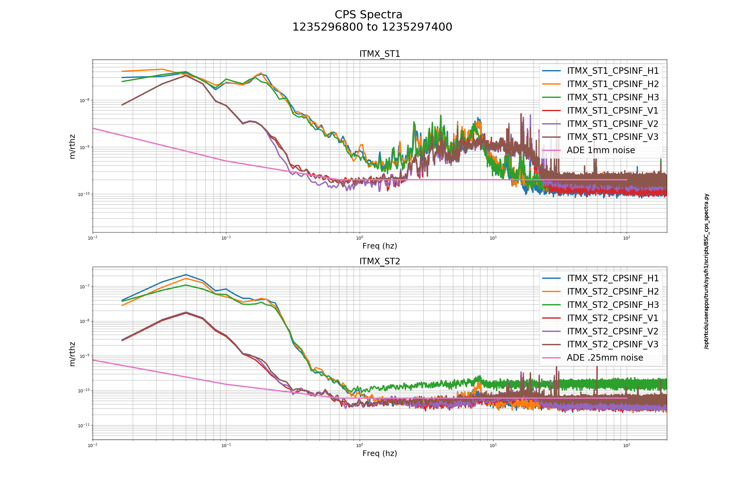
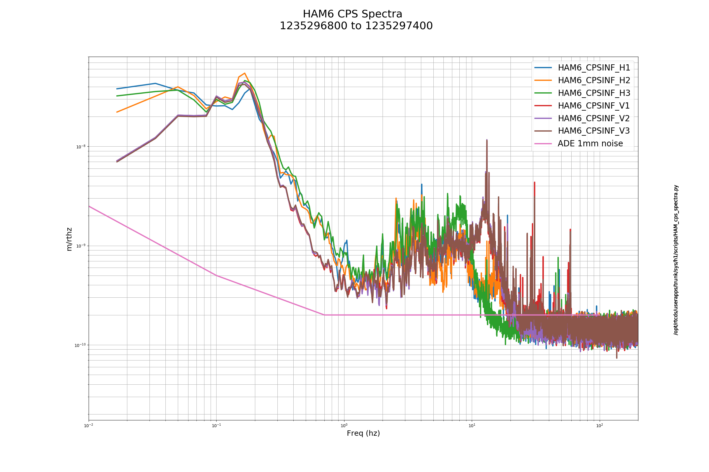
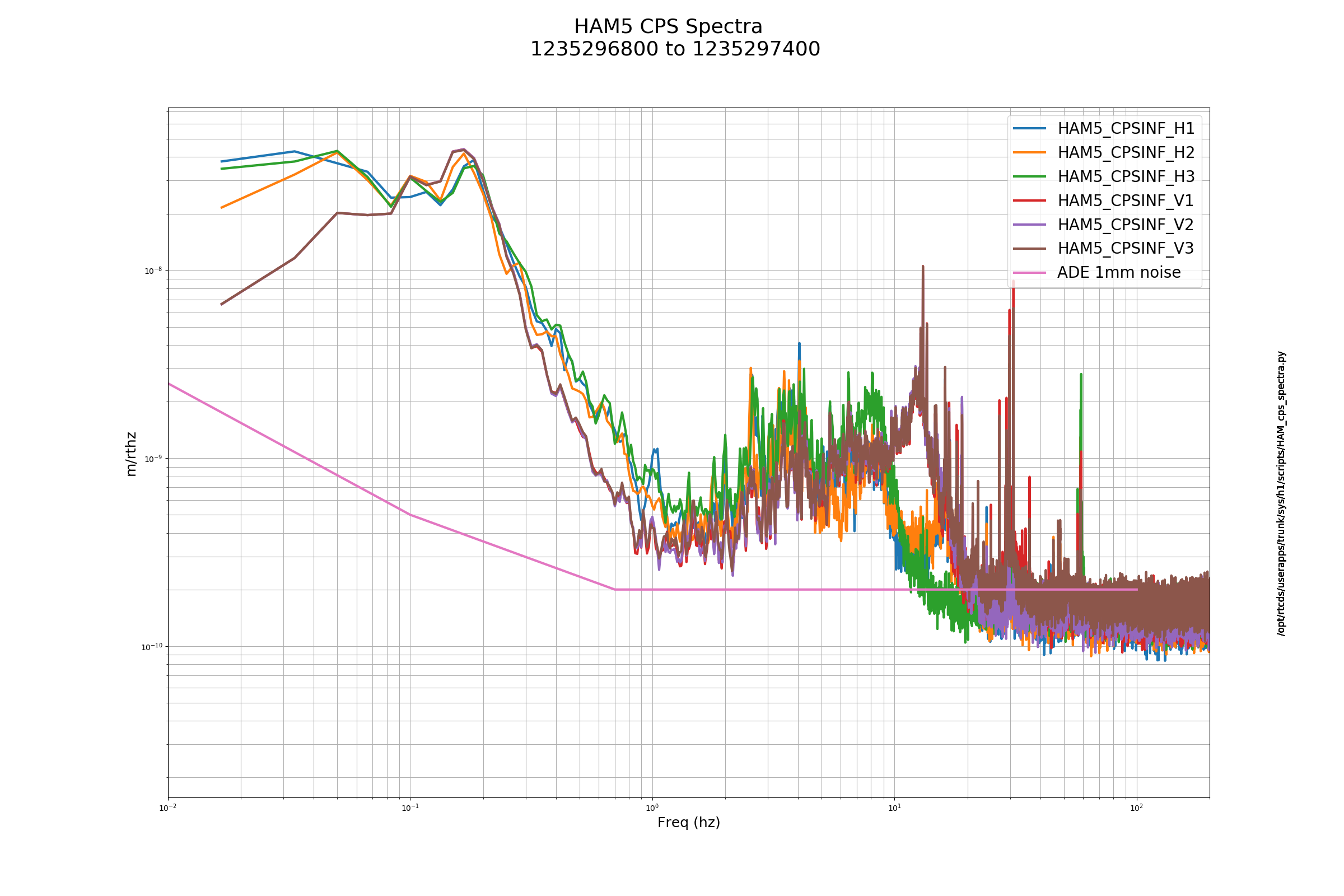
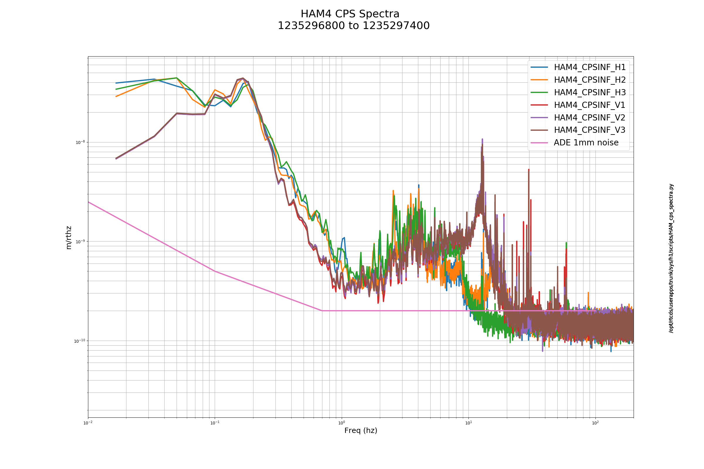
FAMIS8196
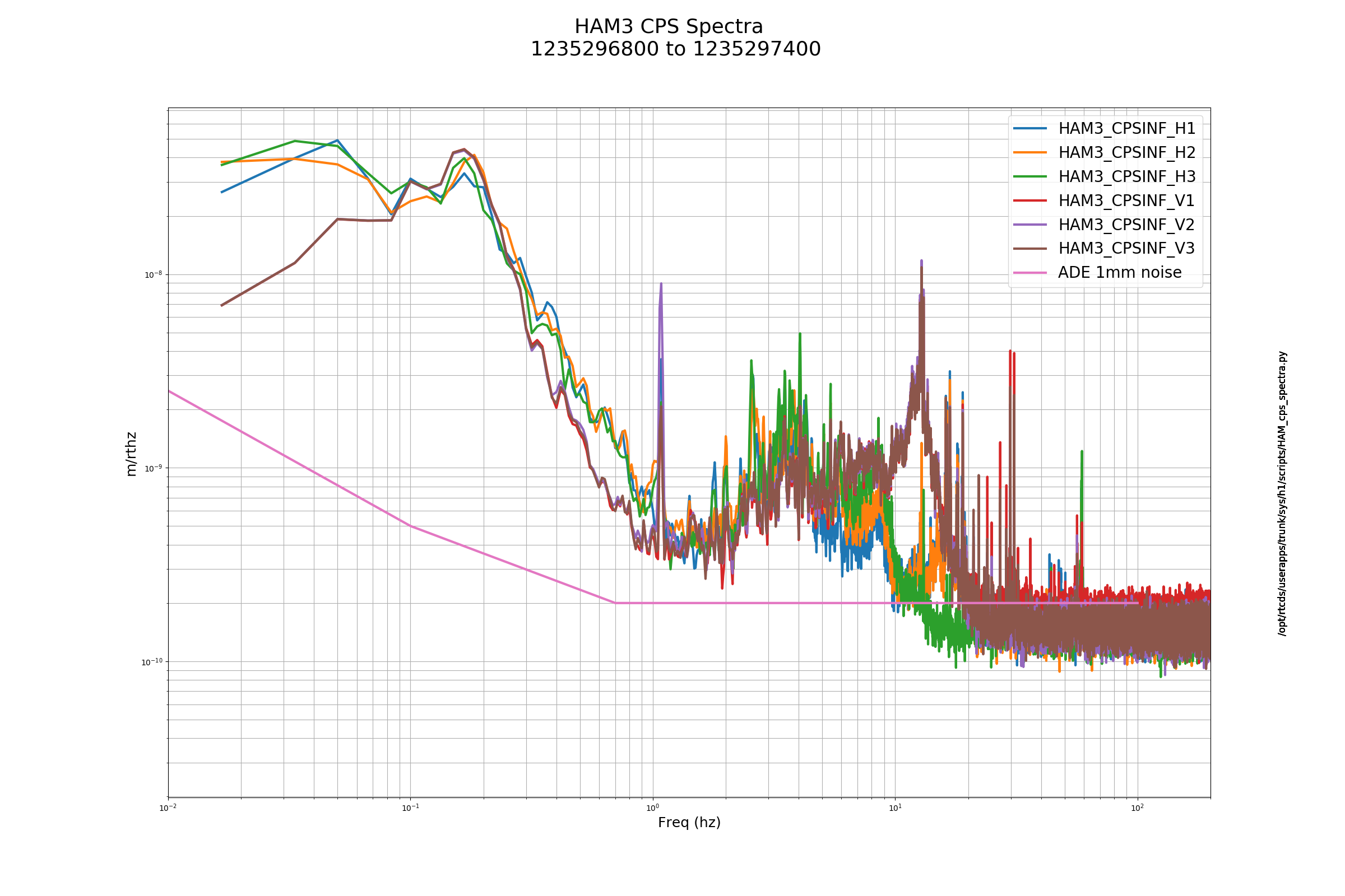
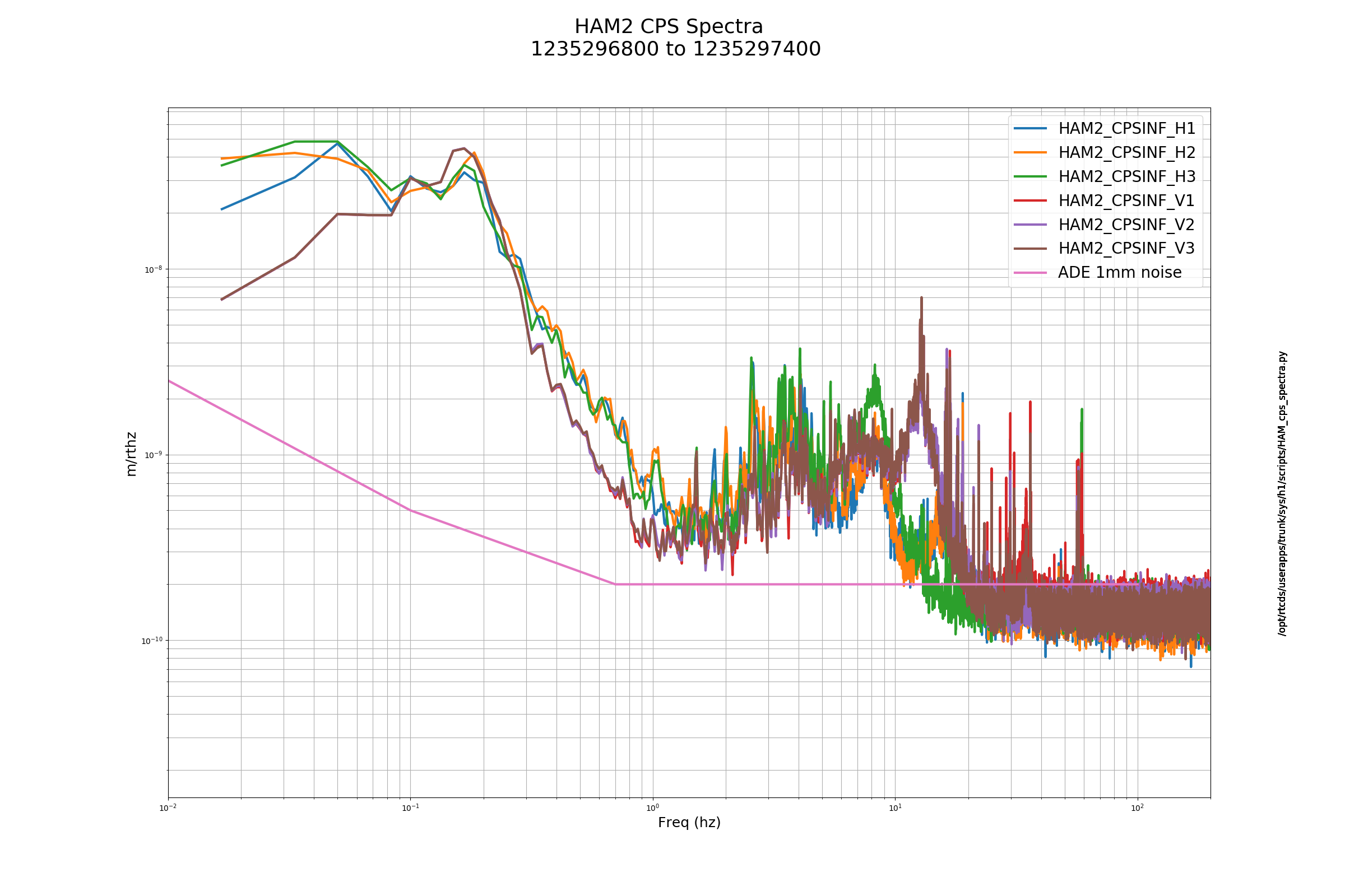
Scripts reported that ITMX_ST2 H3 high freq noise is elevated, I also think that ITMY ST2 V3 also looks high.
FAMIS11001
Laser Status:
Front End Power is 32.74W (should be around 30 W)
70W Output Power is 69.49W
Front End Watch is RED
70W Watch is GREEN
PMC:
It has been locked 0 days, 0 hr 1 minutes (should be days/weeks)
Reflected power = 11.57Watts
Transmitted power = 53.15Watts
PowerSum = 64.72Watts.
FSS:
It has been locked for 0 days 0 hr and 0 min (should be days/weeks)
TPD[V] = 0.006749V (min 0.9V)
ISS:
The diffracted power is around 2.8%
Last saturation event was 0 days 0 hours and 0 minutes ago (should be days/weeks)
Possible Issues: Peter is currently out at the PSL, tweaking the FSS alignment.
FAMIS11206
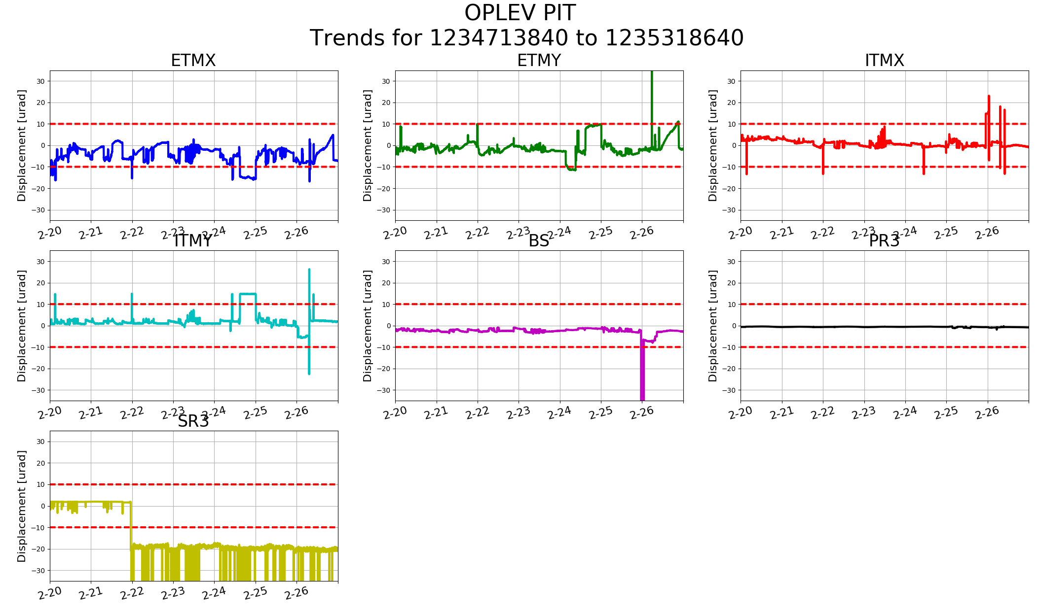
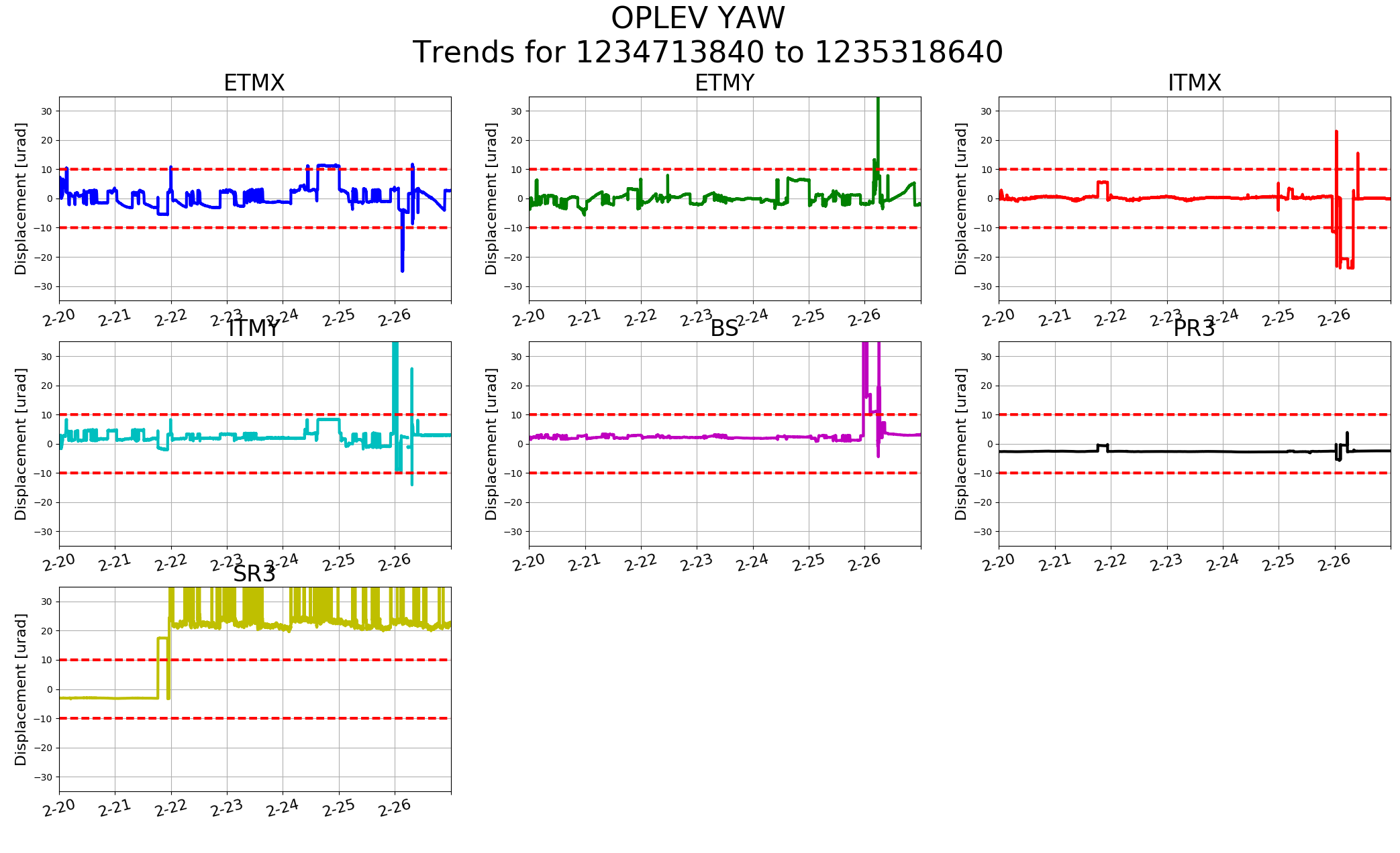
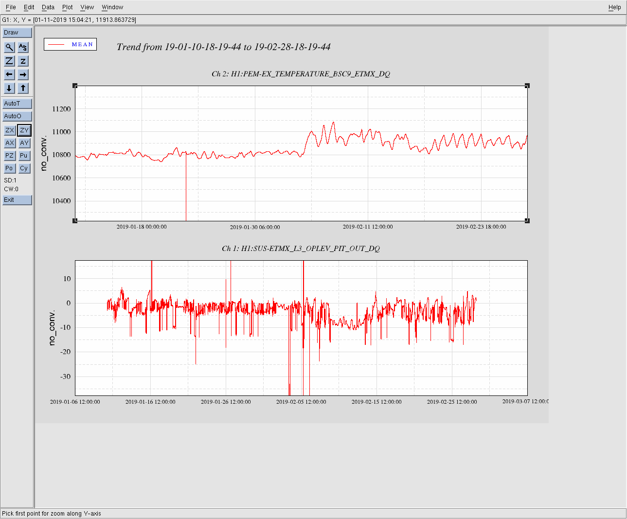
SR3 is a known problem, but besides that ETMX P is nearing 10urad.
Perhaps the leaf springs on the suspension are sagging a bit due to the temperature. It looks like about -6.5 while trying to acquire DRMI. It isn't too, too bad but it could use some luvin'. I wasn't able to make it to the ends last Tuesday.
It looks to be the case.
TITLE: 02/27 Day Shift: 16:00-00:00 UTC (08:00-16:00 PST), all times posted in UTC
STATE of H1: Commissioning
OUTGOING OPERATOR: None
CURRENT ENVIRONMENT:
Wind: 16mph Gusts, 12mph 5min avg
Primary useism: 0.07 μm/s
Secondary useism: 0.22 μm/s
QUICK SUMMARY: Peter is in working on the PSL trying to help with our COMM beatnote issue. Snow and winds on site, please drive safe.
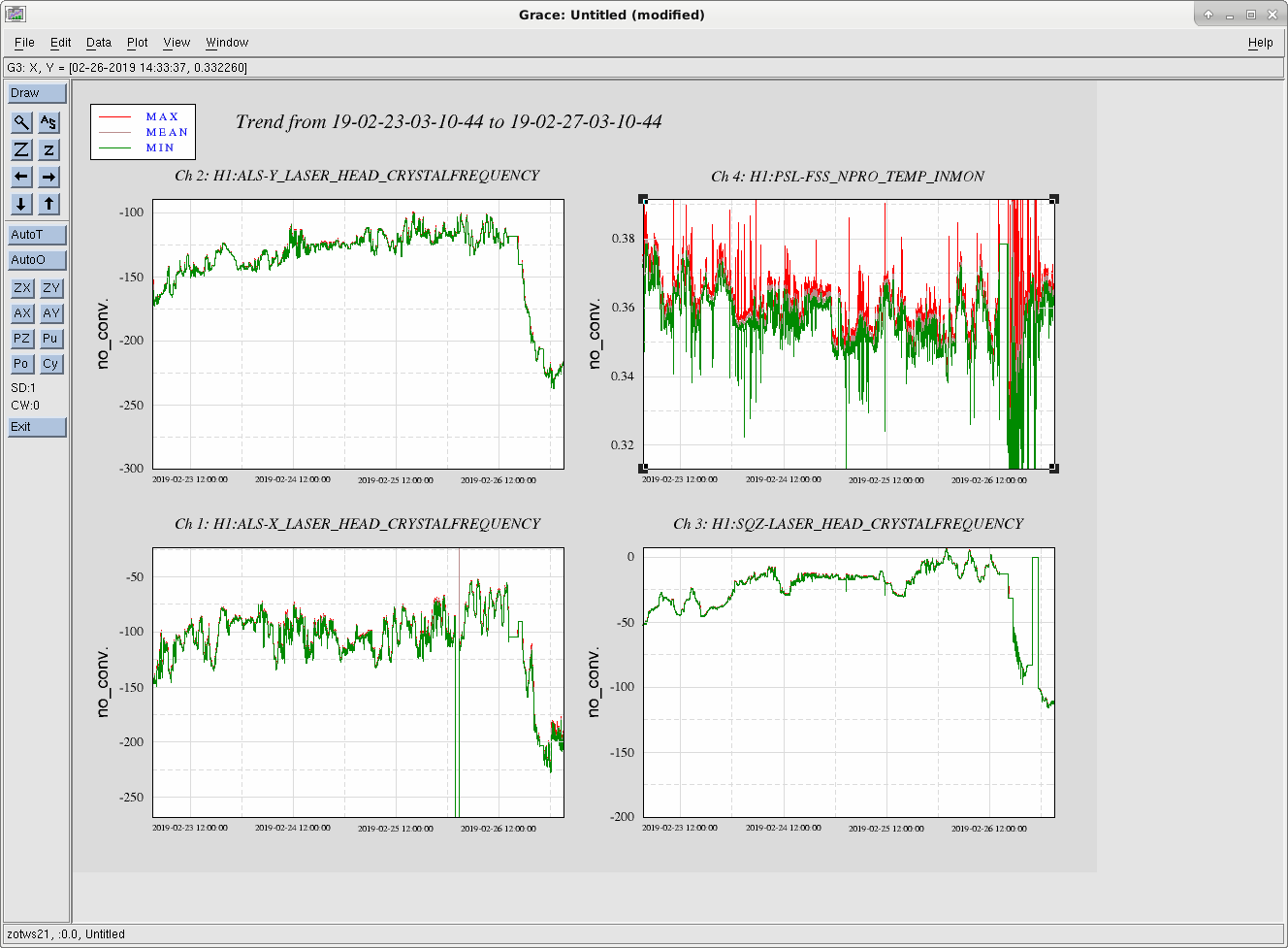
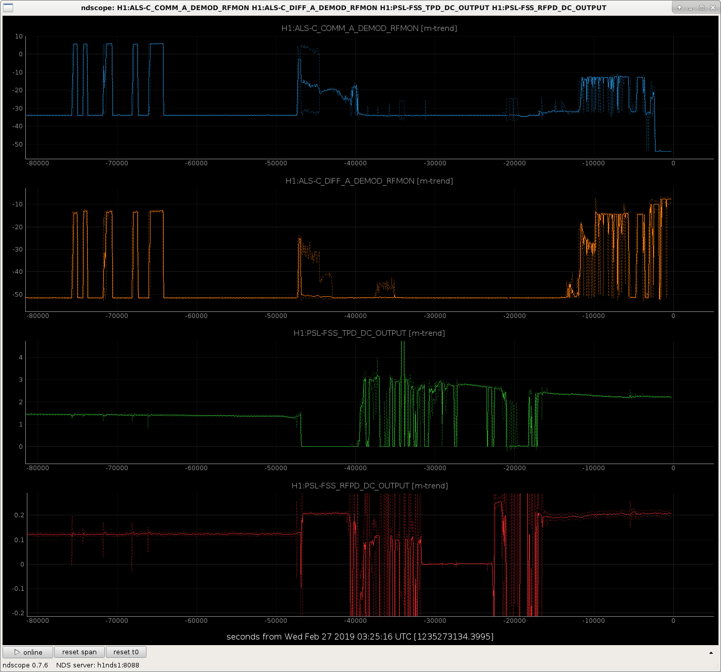
TJ, Daniel, Peter F, Sheila, Jenne, Rich, Dan Brown, Georgia, Craig This morning Peter King and Jason went into the PSL and made some alignment changes to the FSS. We believe that while this was happening, some misalignment occurred which shifted the frequencies of both end station and the squeezer laser, but not the main laser itself (Attachment One). Most likely this is due to some misalignment through the FSS AOM catching a single-pass diffracted beam, and not the expected double-pass. This was first noticed by TJ, who plotted the ALS_COMM beatnote and saw it was low (from +6 dBm to -20 dBm) starting around this morning (Attachment Two). Sheila and Jenne went out to align the beams on ISCT1, but were unable to recover ALS_COMM beatnote. They looked at the beatnote on the scope, and found it was at 240 MHz, and not the expected 80 MHz. ALS_DIFF was still at the expected 160 MHz. The transmitted and reflected power coming from the FSS both increased. Daniel and Peter F looked at all the laser frequencies this morning (attachment one), and found all of them shifted by about 100 MHz except the main laser. I plotted the IMC gain from today and a couple days ago, and found the gain reduced by about half. (attachment three). This is consistent with losing half of our actuation range from the IMC VCO + AOM. We hope that tomorrow morning we can have another incursion into the PSL to see if this is actually the case, and try the realignment again. None of us are going in tonight.
Sorry for holding things up. I have always found then double pass alignment difficult, even more so when the single pass diffraction efficiency is such that the zero order and the first order are about the same.
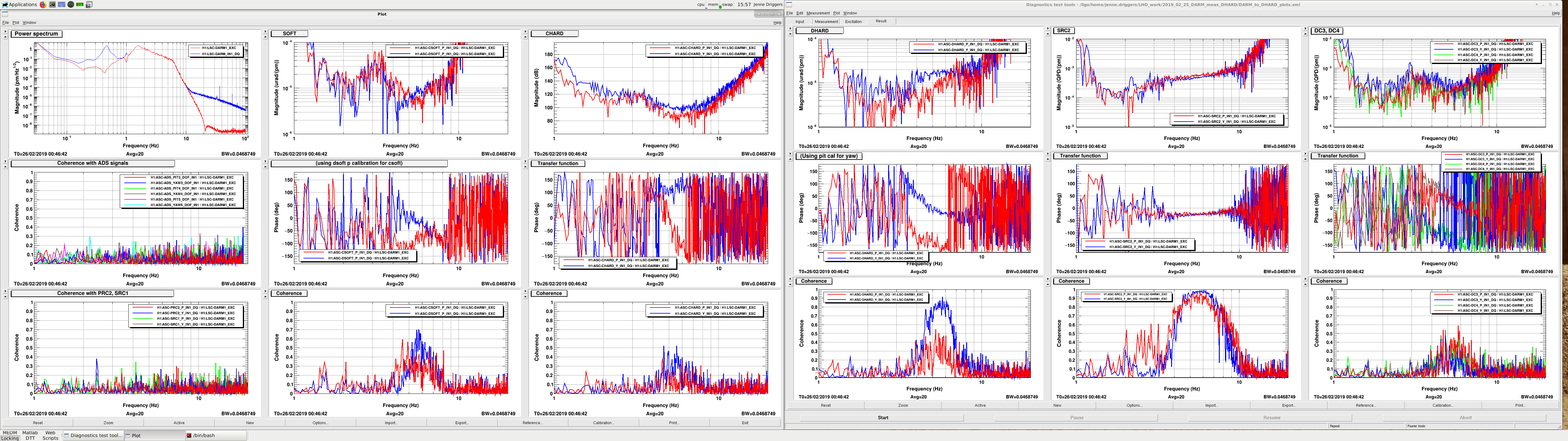
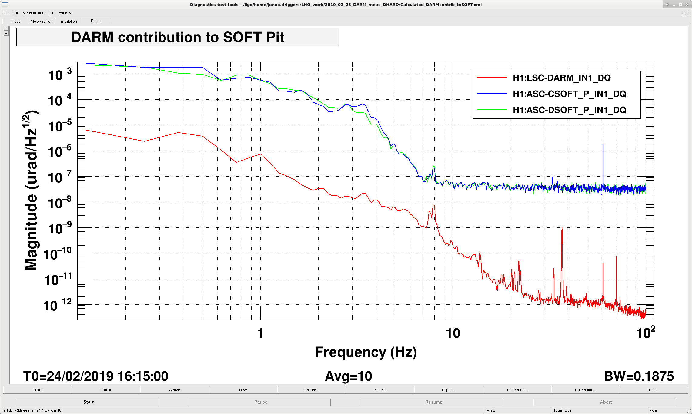
This is a complementary alog to 47078. In that alog, I was exciting DHARD pitch, and looking at how that coupled to DARM and other angular degrees of freedom. Here, I excite DARM (at DARM1_EXC, so going to both stages of ETMX that are in use at the time) while in LOWNOISE_ASC. This state is before we transition the analog coil drivers, and before we transition to 3 stages of actuation (ITMX ESD + 2 stages of ETMY). So, I will redo this measurement again at a time when we are locked on 3 stages of actuation just before we attempt to transition back to ETMX, and drive ETMX directly. But, here is a look at how DARM length couples to angular motion while at 30W in LOWNOISE_ASC.
In the first attachment, I show the various coupling transfer functions from DARM to several angular degrees of freedom. Notably, the SRC2 coherence with DARM actuation is very high, although the DC3 and DC4 coherences are quite low. DHARD yaw's coherence and coupling is a bit higher than DHARD pitch, which was also somewhat surprising to me.
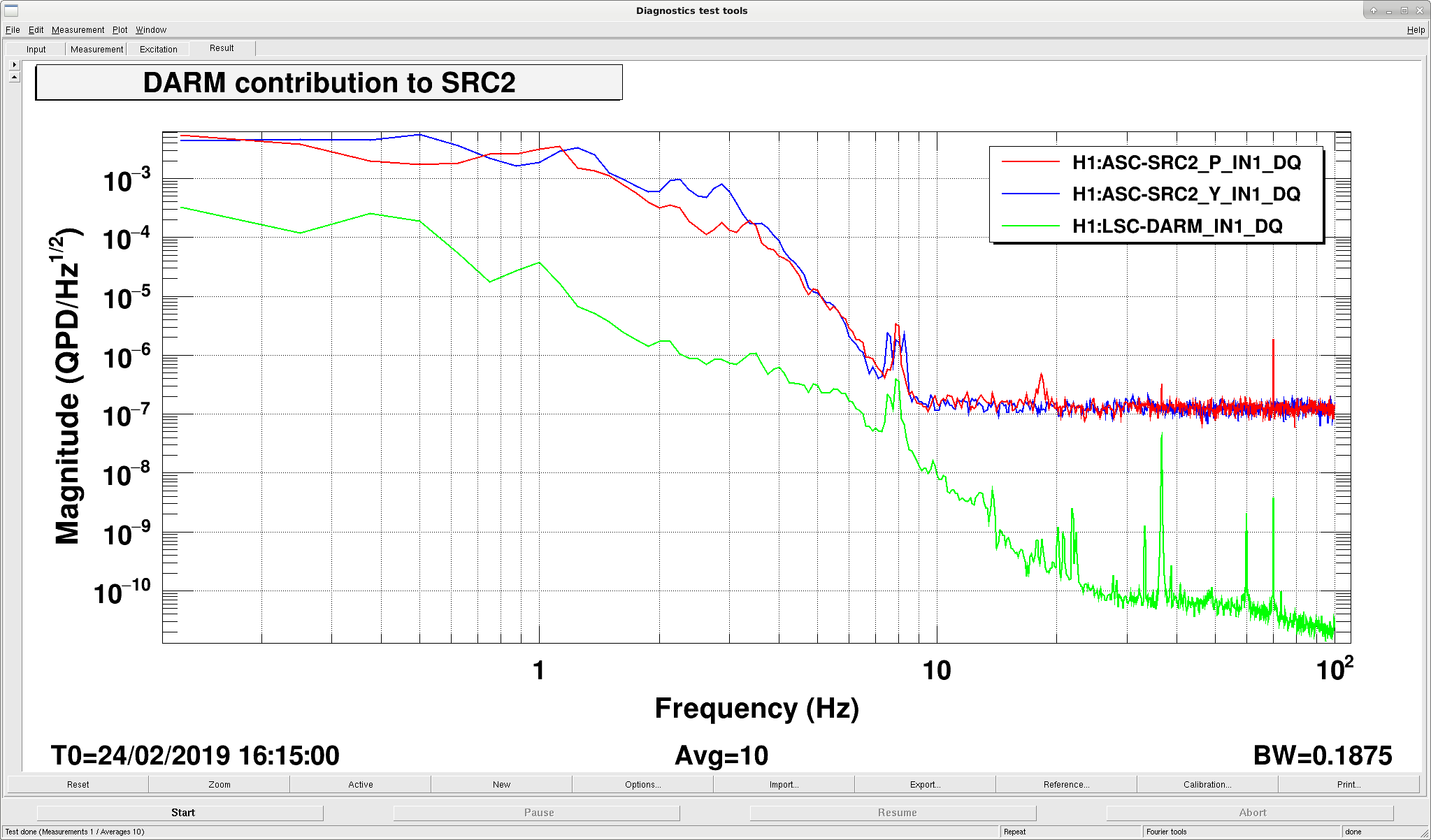
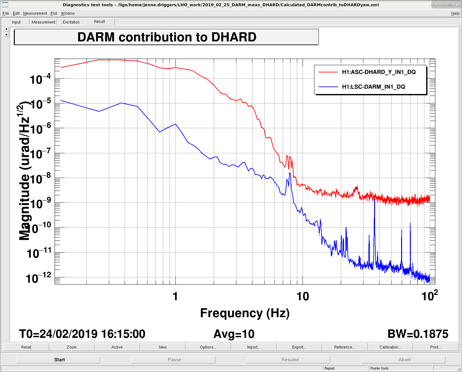
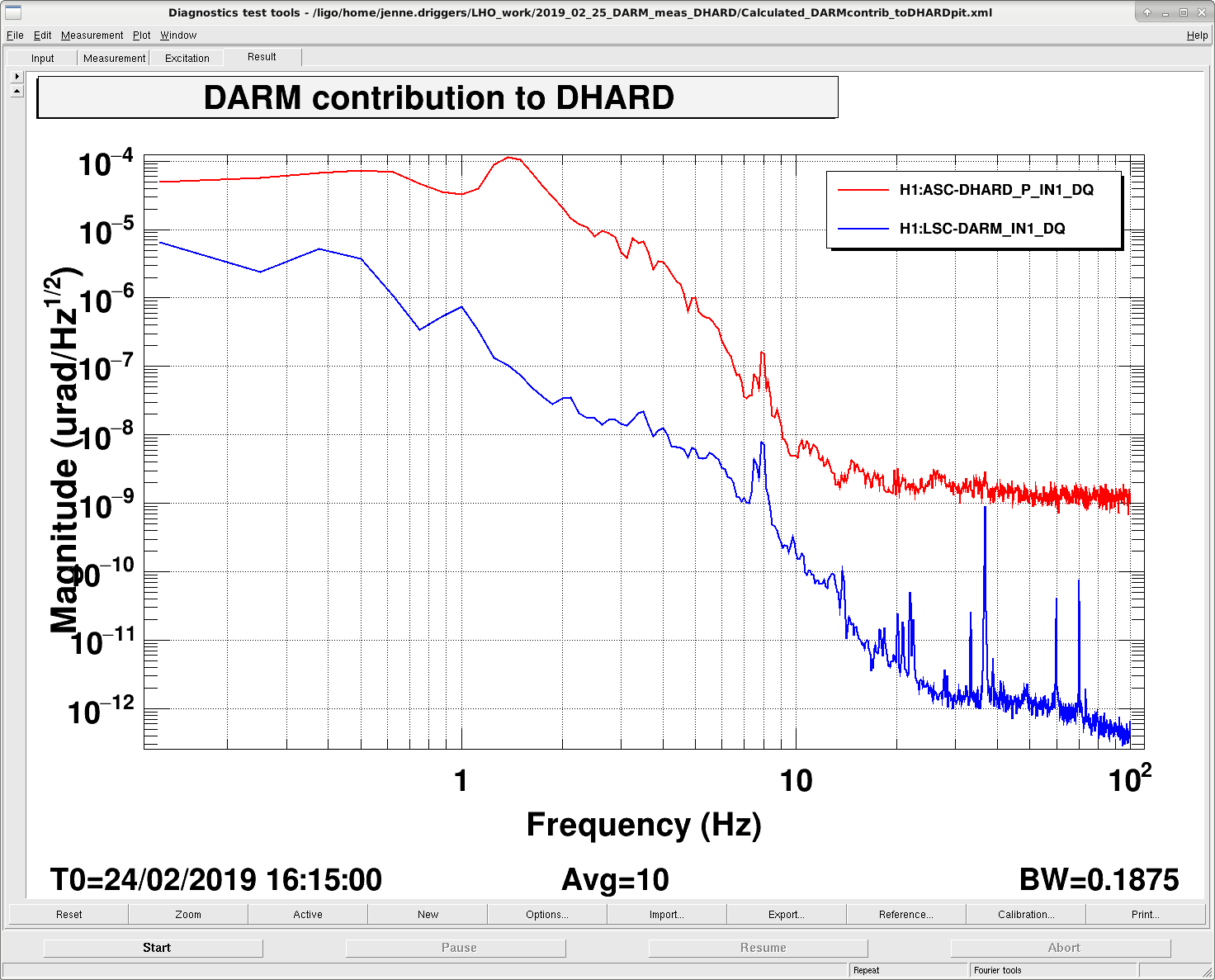
In the other attachments, I plot DARM's contribution to the in-loop noise of various angular degrees of freedom. None of them seem dominated by DARM noise, particularly at our suspicious 4.5 Hz, so I'm not sure that (at LOWNOISE_ASC) length to angle is causing us trouble.
When we have the IFO back, I'll retake these measurements driving ETMX when it's set up for NomLowNoise, but we're locked on IX and EY.
An attempt to address acoustic peaks in DARM that comes from CLF somehow. This is to ensure only the correct polarization from the AOM continues to the coupler (cube --> half waveplate --> cube). I tweaked the alignment to get the transmission back around where it used to be (~80%).
Summary: Looked into the grounding issue as relates to the OMC and potential for coupling of ground related noise (including power line harmonics) to OMC length. It is well known that there is a grounding anomaly inside HAM6 due to a metal cable bracket on the suspended OMC breadboard. See: https://alog.ligo-wa.caltech.edu/aLOG/index.php?callRep=41709 A detailed analysis of the documentation (as listed on the attached PDF) indicates that there should not be such a coupling, however it appears as though there is. This probably means there is an error in the documentation. If this ground path exists, then a method is suggested where a single cut to the shield-to-backshell connection may result in a more favorable situation with respect to the OMC grounding and shielding. A few quick measurements should be made (aided by the attached cartoon) to verify the actual grounding configuration, then a breakout board could be added to accomplish the needed shield break such that the theory could be put to test. If there is a ground connection, as suspected, it would be interesting to know if the same situation exists at LLO, or if it's just a defect in the wiring exclusive to LHO.
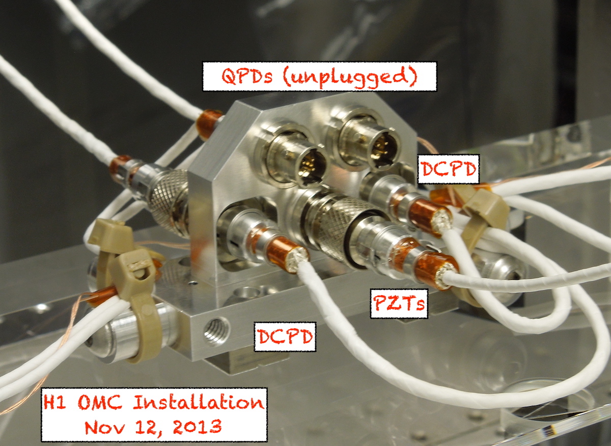
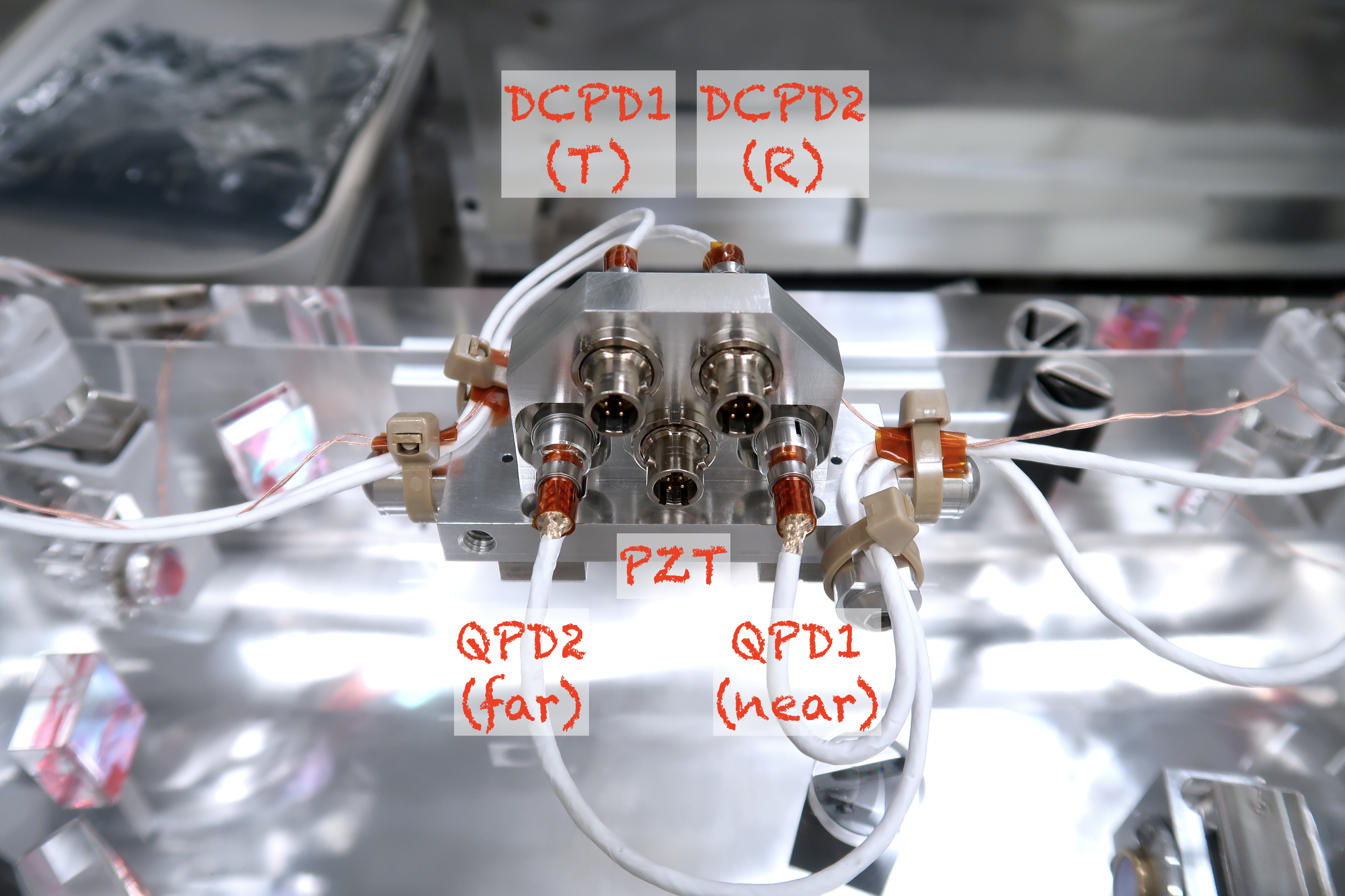
I went through the installation pictures of the H1 OMC back in 2013. I found some photos that show the shields of the mighty mouse connectors are all connected to the connector shells. This means that they are all connected at the metal cable harness. => (D) and (E) in Rich's attachment are connected.
I found the similar photos for L1 OMC and it has the same configuration.
Thanks Koji. I believe what you say, but still have no explanation for why the PZT shield is not connected to the QPD shield? I now fully understand the issue with the DCPD (more to follow on that as I catch up on new cartoons and words)
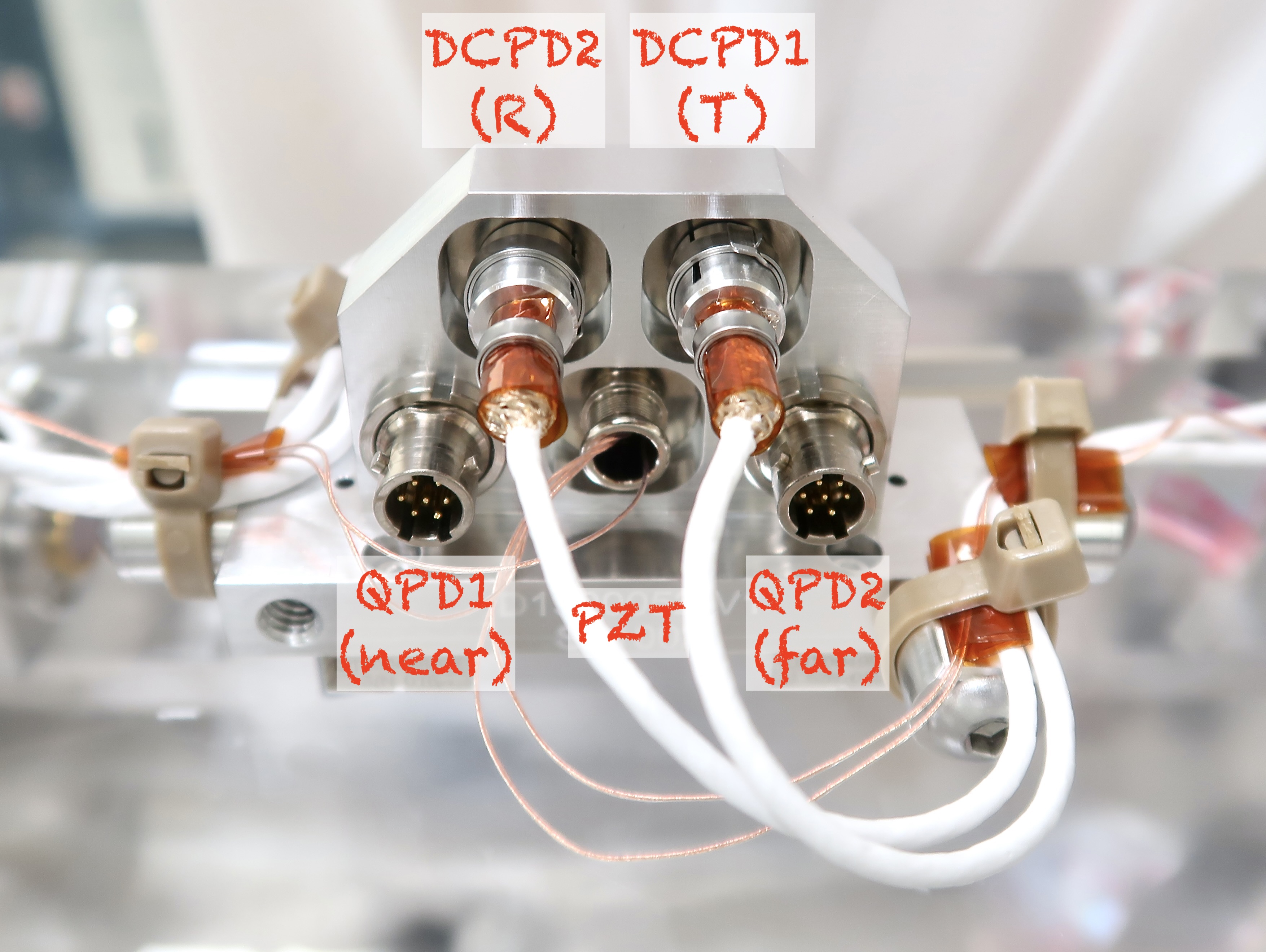
Later-than-too-late comment, but just for posterity, labels for DCPDs and QPDs are swapped in Koji's pictures.
Look at the exposed connectors with 4 pins each in the 2nd picture. Real QPD MM connector has 7 pins (https://dcc.ligo.org/LIGO-D1300375).
Comfirmed. I agree with Keita.
Are these also the pictures of H1 OMC?
Strictly speaking, no. These are the pictures of OMC #002, which was the former (original) LHO OMC and has been refurbished to be the new LLO OMC.
WP#8101
Created 6 new SC nodes for HAM1 and BSC HEPIs. They use the same base code as the other SC nodes, so not much new here. Jim has updated the SEI_CONF manager, and I updated the overviews (though not the ISI_CONFIG.adl screen).
The SEI_CONF node has not been tested with these new nodes yet, so be wary using it and feel free to call Jim or I if there is a problem.
A quick entry whilst things are still fresh in my memory, more details to follow.
Adjusted the double pass alignment through the AOM. Re-centered L12 and the 21.5 MHz EOM to match (component
names match those on the PSL table layout). Without the 21.5 MHz connected, measured 43.8 mW at the base of the
periscope, and 40 mW after the polarising beamsplitter cube before the RF photodiode. Measured 4.38 mW in front
of the RF photodiode.
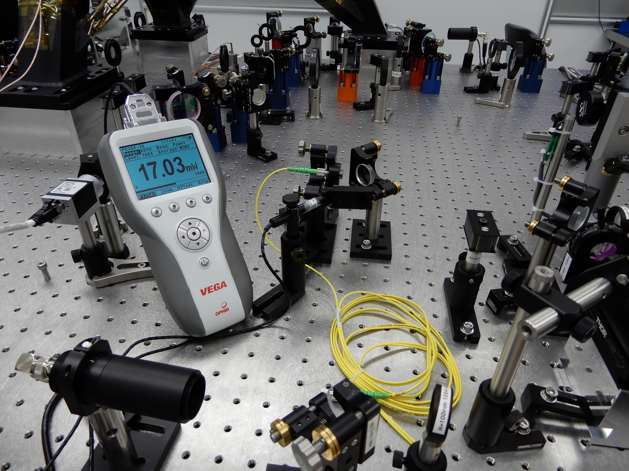
Locked the FSS. With a reference cavity transmission signal of 3 V, measured 17 mW in front of the ALS fibre
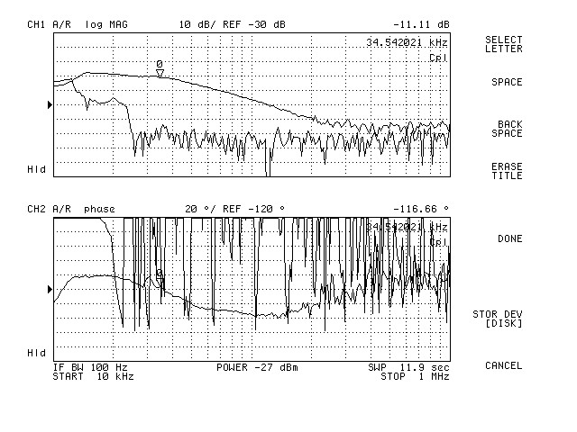
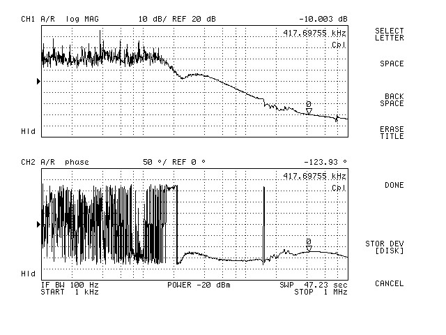
(see ALS_Fibre.JPG). After the alignment tune up, measured the transfer function (see PC.jpg). It was here where
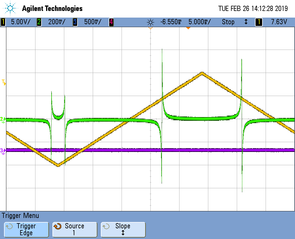
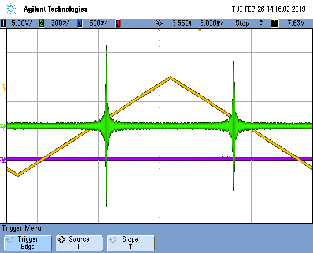
things went AWOL. Swept the reference cavity by applying a ramp to the PZT and displayed the mixer monitor signal
on an oscilloscope (see scope_0.png). This was noticeably different from the same measurement taken before lunch,
where the discriminator signal was less than ~10 mVpp. The RF output of the RF photodiode is shown in scope_1.png.
Left the FSS with a common gain of 25 and a fast gain of 16 (see CG25FG16.jpg) where the UGF is ~417 kHz.
Increasing the common gain slider by an extra dB or two to sit on the peak of the phase bubble makes the PZT
prone to oscillating.
Jason / Peter
Also investigated the readback of the RF photodiode output. Injecting a known voltage into the breakout box (DB9 side) produced the correct number of counts displayed on the MEDM filter module display associated with the RF photodiode DC readout (~150 counts for 10 V input). Richard / Fil / Peter
Tried the slightly newer version of the TTFSS (2G). Had to flip the RF phase by 180 to get the
servo to lock. However with both the common and fast gain sliders at minimum the PZT was
oscillating. The discriminator signal was a lot larger with the 2G TTFSS than with the TTFSS
currently installed.
A 10 dB attenuator was inserted in the LO path to bring the LO monitor to be about the
same. This because the 2G TTFSS has an RF amplifier inside.
I will have to compare the electronic transfer function of the EOM path with the original
TTFSS. I already know the PZT path is the same except for a notch filter.
Seems that, if 10V only gets you 150 cts on the ADC, it is broken.
Associated with FRS Ticket 12386.
Tuesday Morning CDS activities:
The EX ESD electronics are currently being powered off temporary power supplies that are in the VEA next to SUS-R1 rack. This temporary setup is to help with the ongoing noise hunting of the IO chassis fan noise seen in DARM (alog 46983). This morning we placed the safety vacuum interlock on the HV power supplies. Interlock will turn off the HV power supplies if the vacuum pressure is not within a specified range.
While doing this work the low voltage power supply was accidently turned off (±18V and ±48V) and restarted. It was later discovered that the ±18V thermal breaker on the LN ESD chassis had tripped. Thermal breaker was reset and all front panel lights came back on. Operator confirmed he was seeing reasonable readback signals. Looked at the power supply and saw about .4A on both legs, but can't remember if it was for the ±18V or the ±48V.
Ran new cables from the ISCTEX table to SUS-R1. These will be used to remotely enable the table lights, TCS LED lights, and monitor table fan status.
TITLE: 02/27 Day Shift: 16:00-00:00 UTC (08:00-16:00 PST), all times posted in UTC
STATE of H1: Commissioning
INCOMING OPERATOR: None
SHIFT SUMMARY: Long Maintenance Tuesday due to a model issues and PSL FSS. Initial alignment is currently underway.
LOG:
1345 Peter King to PSL, currently locked and seemed to stay locked for a bit
1545 Rick to EY for PCal
1549 Vanessa to EX
1613 Chandra to MX, Pfiefer to high bay to crane
1627 Niko to EY to join Rick
1629 Hugh, Corey starting HEPI accum. CS maint.
1632 Chandra to MY. One Pfeifer member will stay there.
1635 Karen done at EY, heading back
1644 Fil to LVEA to replace power supplies at HAM6/SQZ rack
1645 Chandra to EY with Pfeifer
1657 MX Vanessa to MX
1706 Fil out, heading to EX to start on ESD interlock
1718 Chris S to EY then to EX
1719 Gerardo to MY
1722 Pfeifer crew from EY going to EX mech room
1740 Jim taking the EX SEI
1740 Gerardo to EX, MX, EY
1745 Jeff K starting EX PUM meas.
1807 Jason to PSL
1831 Vanessa from MX to CS
1835 Danny to LVEA to get HWS filter
1845 Hugh, Corey done at CS, moving to EX
1846 Kara to LVEA
1846 Danny out, now to EY to put filter on HWS table
1848 Chris back
1910 Gerardo back
1917 Nutinee to LVEA to ISCT6 and SQZ Bay
1928 Pfeifer back from ends
1938 Richard to PSL enclosure
1938 PCal crew done
1942 Hugh, Corey form EX to EY
1946 Richard out
1959 Dave restarting models: asc, sqz, hpi, isi (ex/ey), sei proc, tcs cs
2007 Keita to LVEA to check OMC DCPD ground
2009 DAQ restart
2010 Jason, Peter K out
2034 Hugh, Corey finished at EY
2037 TJ to LVEA to place HWS temp senspr
2037 Richard, Fil to LVEA for DC voltage on PSL PD
2047 Keita out
2050 Bubba to EY to get site car unstuck
2054 Peter to PSL enclosure
2057 Danny back
2100 TJ out
2114 Jason out to PSL enclosure to help with FSS investigation
2118 Richard and Fil out
2129 Jeff K done with measurements
2137 Dave restarting isi, hpi, asc model and DAQ restart
2205 Fil to LVEA to bring parts to PSL crew
2258 Chandra to MY
2309 Fil to EX to check on ESD
2333 Nutsinee to LVEA ISCT6
2337 Fil back
Power cycle h1susb123 to fix misbehaving ADC channel
Richard, Dave:
h1susb123 computer and IOChassis were power cycled to fix an ITMX ADC channel.
WP8100 SQZ guardian node name change
T.J., Nutsinee:
SQZ guardian node names were changed (new INI file required DAQ restart)
HEPI Senscor Guardian nodes added
T.J.
SC nodes for BSC and HAM1 HEPI was added to guardian (new INI file required DAQ restart)
WP8095 h1sqz model change
Sheila, Daniel, Dave:
A new h1sqz model was installed, addition of slow channels required a DAQ restart.
WP8097 h1asc model change
Jenne, Daniel, Dave:
A new h1asc model was installed for bullseye sensors, two restarts were done.
WP8094 h1lsc model change
Dan B:
A new h1lsc model was installed, no DAQ restart was needed.
SEIS Senscor Changes
Jim, Hugh, Dave:
New HEPI models for all BSC and HAMs were installed, also new endstation ISI models and h1seiproc.
Some IPC and DAC issues were found which required some restarts of models and DAQ.
WP8022 channel name fix in h1tcscs
Danny, Dave:
A new h1tcscs model was installed to fix a typo in a channel name, DAQ restart was required.
Beckhoff EX PLC[1,2] changes
Daniel, Patrick, Dave:
New h1ecatx1plc[1,2] code was installed. PLC1 added 6 enclosure records to the DAQ, PLC2 added an RFAMP channel.
h1sysecatx1plcsdf was restarted against a new monitor file.
DAQ restart
Dave:
DAQ was restarted at 12:09 and 13:41 for the above changes. Restart-time second trend files were renamed later for NDS reconfiguration purposes. I fixed a slight oversight in my script which checks for duplicate DAQ channels, it now combines the INI and PAR channels into one large list before looking for duplicates.
To avoid confusion for those who look at these guardians remotely,
SQZ_LOCK_L1, SQZ_OPO_L1, SQZ_CLF_L1, and SQZ_LO_L1
Changed to
SQZ_LOCK_LR, SQZ_OPO_LR, SQZ_CLF_LR, and SQZ_LO_LR
"LR" For "Laser Reference" scheme to distinguish from the existing guardians that work on the OPO reference scheme previously used.
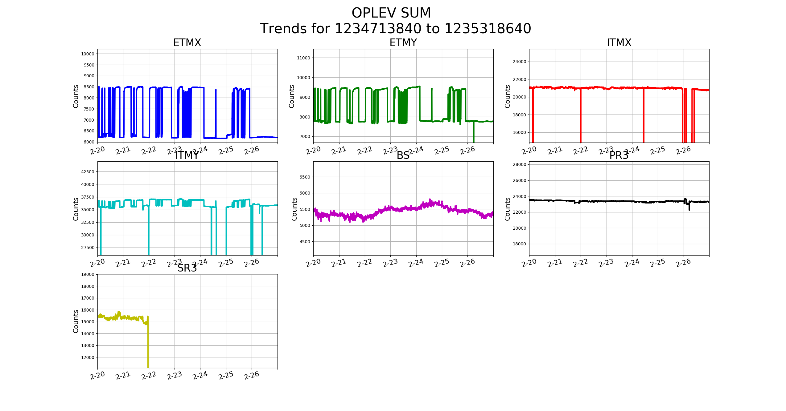
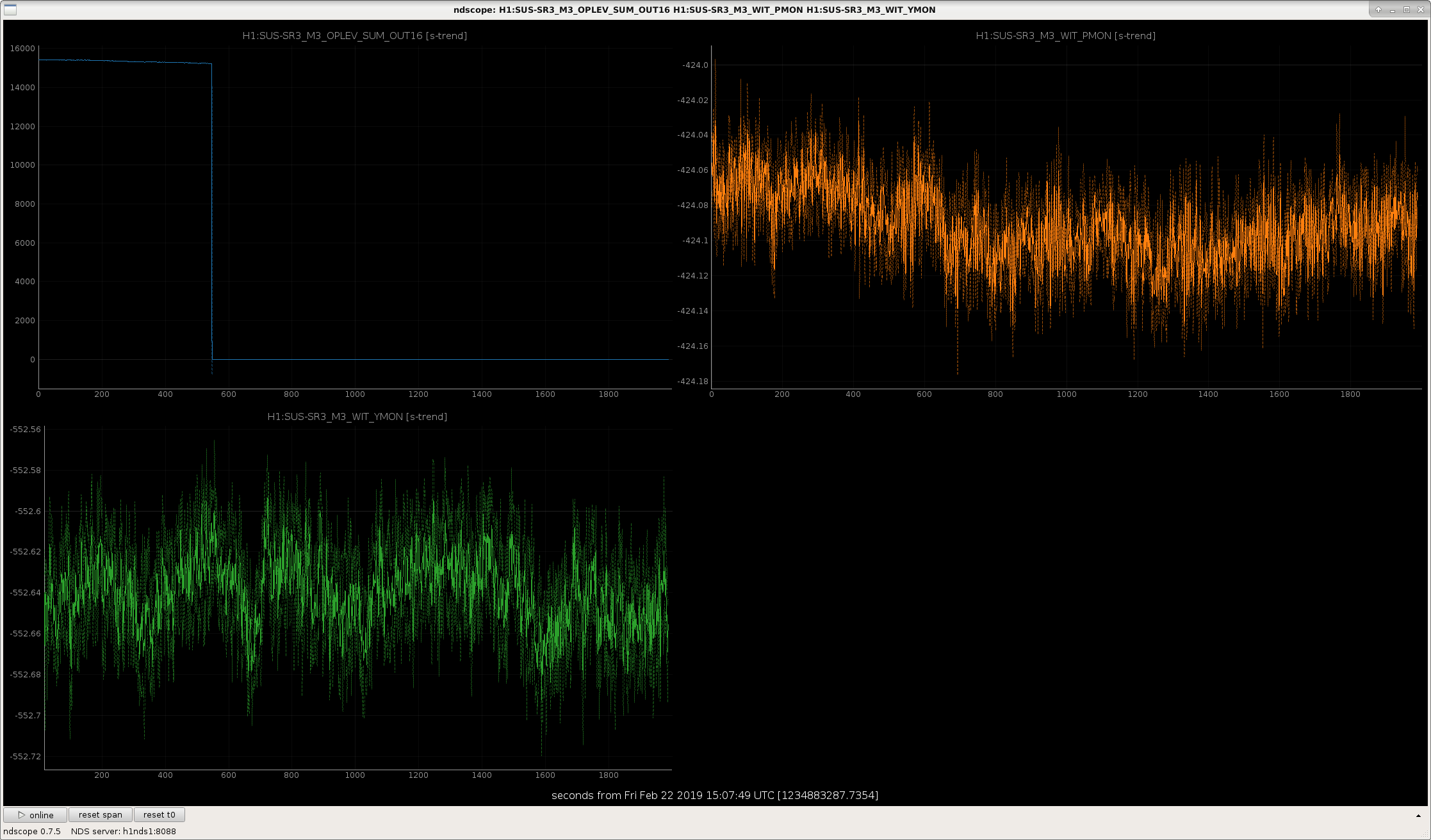
Just noticed a warning on DIAG_MAIN that SR3 oplev was low. SR3 is aligned, and I restored all SEI to their nominal status (clicked "recover EQ", and requested sensor correction to be WINDY), so there should be no reason for SR3's oplev to be low.
Attached is a plot of the Oplev sum, as well as the lowest stage OSEMs, showing that the optic didn't move, but the sum disappeared.
Recall that we do not use the SR3 oplev for any damping, so while we should fix this soon, we shouldn't break lock to do so.
Now associated with FRS Ticket 12394.
Will investigate at the next available opportunity, likely during the next maintenance window (2-26-19), unless this gets deemed a higher priority. Tagging this as AOS in addition to SUS (OpLev is technically an AOS system).
The laser is definitely dead. Unfortunately, due to a series of consecutive failures in the lab while tweaking our spare stock for glitch-free operation, we currently have no spare lasers; all of our spares (our 3 designated spares and 2 others) are currently getting refurbished. I have pinged the manufacturer for an update, will request a loan from 3IFO to use in the interim.