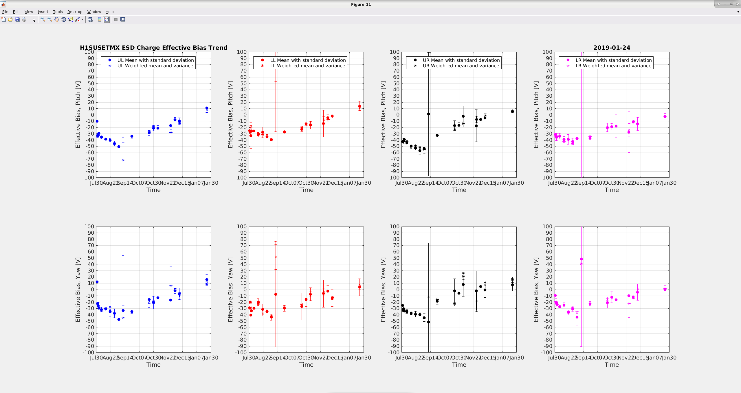
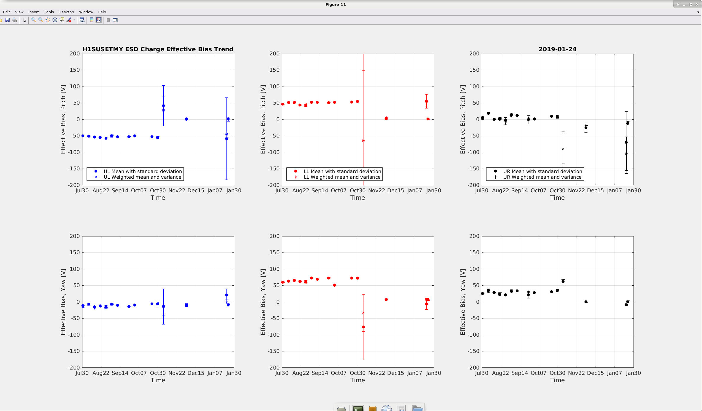
TJ, Betsy and Rahul Today morning at 8.10 am, we started performing the charge measurements on the ETMX and ETMY, since the interferometer was unlocked. Initially we did 5 measurements, however Jeff Kissel found out that the DAC was constantly being saturated (alog 46621). He fixed it by reducing the quadrant drive amplitude from 124k to 110k, with a 20 bit DAC (former was 18 bit DAC). Hence, we had to redo the measurements again for the ETMX. Due to paucity of time (priority was to lock the interferometer in the morning) we had to truncate the measurements and we could get only 3 data against 5. Later we analyzed the data on MATLAB, and the long term trends are shown on the plots attached. For the ETMX the effective bias is at 10 V, which looks very good. Comparing this to the data which we took on the 22 Jan (Tuesday) (alog 46582), which looked very bad (effective bias -90V, STDEV +-70V). We believe that there is some error on the measurements from 22 Jan, with very large standard deviations and thus have deleted this from our latest plot. For the ETMY the effective bias is almost at zero, which is excellent.
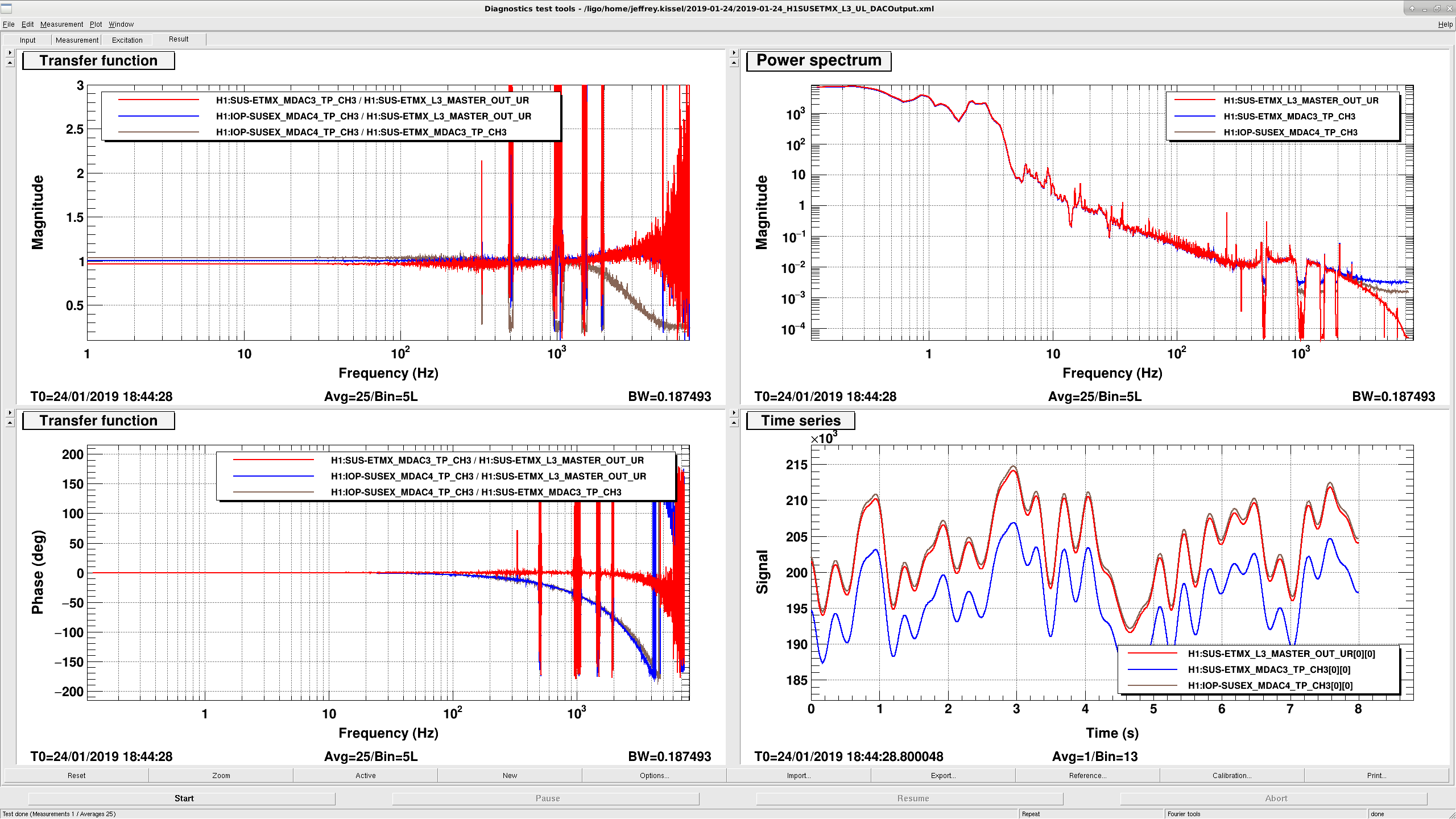
J. Kissel FRS Ticket 12201 Inspired by the problem with charge measurements this morning (LHO:46619), I took a look at test points of the DAC output for SUS ETMX L3's UL ESD quadrant during a stable state of lock acquisition (specifically on ALS DIFF, and thus NOT saturating) in order to help understand at what point of requested digital counts that the DAC saturates. Attached are the results. The DC values of the transfer functions are as follows: Request > USER Out 0.966245 Request > IOP Out 1.00299 USER Out > IOP Out 1.03802 Why there's this gain divide-down then back-up between the Request, USER Out, and IOP, I don't know. However, it does mean that when requesting, say 400000 ct out of the DAC, it'll actually send out 400000 * 1.00299 = 401196 ct out of the IOP. That would also mean that a digital request of the theoretical maximum of the 20-bit DAC, 524288 ct, would actually try to send out 544221.42976, i.e. too much by ~19933. Thus the real saturation limit is 2^19 / 1.03802 = 505084 ct, i.e. 3.6% less than you'd expect. I also attach the DTT template if one needs to repeat this test (note that only the request channels are stored in the frames, so the test must be done live). Channel map for SUS ETMX L3's UL ESD quadrant: Request H1:SUS-ETMX_L3_MASTER_OUT_UR USER Out H1:SUS-ETMX_MDAC3_TP_CH3 IOP Out H1:IOP-SUSEX_MDAC4_TP_CH3
Just in case it was not clear, this gain dance on the way out to the DAC is the case for 18-bit DACs as well, and thus is likely not any issue with any particular DAC type, and instead a fundamental truth of the RCG code jumps between user request, the USER out, and the IOP out. See attached for the same study on ETMX's M0 F3 coil channel (this time locked on RF DARM, but there's no appreciable drive to the TOP mass besides the local damping loop output, some very slow ASC offloading, and a large [but removed from the FFT] DC offset).
Data captured with the same template, just in a new plot.
Template lives in
/ligo/home/jeffrey.kissel/2019-01-24/2019-01-24_H1SUSETMX_L3_UL_DACOutput.xml
Digital AI/AA filters with DC gain errors?
Nutsinee Daniel
Sometime back Marc implemented the changes of ECR E1800041 to the spare VCXO D1600500 with S/N S1700238. We then promptly forgot about it, until we encountered a calibration discrepancy in the VCXO drive that indicated that we were missing a factor of 1/25 in gain. Today, we swapped the current unit S1700237 with the spare, which eliminates the 1.6Hz/40Hz pole-zero pair and uses an AT cut crystal. As an added benefit we now need a lot less gain in the CLF CM board and the DAQ readbacks no longer overflow.
The output of this VCXO goes to the bottom pre-amp which drives AOM2 (AA Opto Electronic MT200). There's a 10dB attenuator at the input. We gain a couple of extra dB but we should still be within range of max power allowed to drive that AOM (previously we had 6dB attenuator here, that would have been marginal).
The DMT group requested that some channels be added to the DAQ-DMT broadcaster before next Tuesday, so monitors can be tested on the dmt test machine before rolling them out to production next Tuesday.
h1broadcast0 was restarted at 10:36 PST, the new channels are shown below:
+[H1:CAL-CS_TDEP_PCAL_LINE1_COMPARISON_OSC_FREQ]
+[H1:CAL-CS_TDEP_PCAL_LINE2_COMPARISON_OSC_FREQ]
+[H1:CAL-CS_TDEP_PCAL_LINE3_COMPARISON_OSC_FREQ]
+[H1:CAL-CS_TDEP_PCAL_LINE4_COMPARISON_OSC_FREQ]
+[H1:CAL-CS_TDEP_SUS_LINE1_COMPARISON_OSC_FREQ]
+[H1:CAL-CS_TDEP_SUS_LINE2_COMPARISON_OSC_FREQ]
+[H1:CAL-CS_TDEP_SUS_LINE3_COMPARISON_OSC_FREQ]
+[H1:CAL-INJ_STATUS_OUT_DQ]
+[H1:GRD-IFO_OK]
+[H1:SUS-ETMX_L1_CAL_LINE_OUT_DQ]
+[H1:SUS-ETMX_L2_CAL_LINE_OUT_DQ]
+[H1:SUS-ETMX_L3_CAL_LINE_OUT_DQ]
J. Kissel, R. Kumar, T. Shaffer, B. Weaver Rahul and TJ were running another round of charge measurements this morning because Tuesday's results didn't come out well. Upon getting in, and happened to have had the ETMX screen open, I notice that the charge measurement's drive on each quadrant was constantly saturating the DAC. As the Dothraki say, "it is known" that (for an as-yet-unknown reason) our new 20-bit DAC on ETMX L3 stage (see LHO:44905) -- even though it's billed to have the usual 10 V range -- has less range before front-end code complains of saturation**. Thus the charge scripts, which request to drive the full range (well, 124k ct of the theoretical +/-131k ct) of the 18-bt DAC, were now saturating new DAC. *** As such, I've reduced the drive amplitude to the quadrants to 110k in the charge script for ETMX: /ligo/svncommon/SusSVN/sus/trunk/QUAD/Common/Scripts/ESD_Night_ETMX.py The charge team will post an aLOG of the (hopefully improved) results in a bit. ** This is why our ETMX ESD Bias Voltage has been set to 9.3 V_DAC (372 V_DAC) instead of the O2 level of 9.5 V_DAC (380 V_ESD). I found this out while recovering from when the DAC was swapped from 18 to 20 bit DAC (LHO:44905), and failed to report it. Further, after calling Joe Betz, he confirmed that LLO had to do the same thing (and also failed to report it). Think it's time to report it! I'll create an FRS Ticket shortly. *** You would think 124k would only be 23% of the +/- 2^19 ct range of the 20-bit DAC, but no --more details--blah-blah-- we compensate for have a 20-bit DAC with a gain of 4 down-stream of where the charge measurement script drives [see LHO:44905], so the drive calibration is still in 18-bit DAC units.
J. Kissel for "the crew" We're down this morning for two things: - Charge measurements (which failed on Tuesday -- details to come) - Further investigation on HAM3 ISI 1.something Hz problems. We'll resume the Mpc fight at ~10/10:30p.
TITLE: 01/24 Day Shift: 16:00-00:00 UTC (08:00-16:00 PST), all times posted in UTC
STATE of H1: Commissioning
OUTGOING OPERATOR: None
CURRENT ENVIRONMENT:
Wind: 5mph Gusts, 4mph 5min avg
Primary useism: 0.02 μm/s
Secondary useism: 0.25 μm/s
QUICK SUMMARY: Arrived to the IFO locked, but at around 730 local the range dropped and DARM showed bad low frequency and slowly ringing up violin modes as well as their higher order harmonics. Not sure what is causing this yet, but I may need to kill it if I can't figure it out.
Georgia, Sheila, Koji, Danny, Craig
BRUCO:
A BRUCO scan that Jonathan Richardson helped me to run can be seen here. Things of interest in the BRUCO scan are broad coherences with PRCL signals, angular noise polluting DARM up to 45 Hz, and coherence with the septum accelerometer at 90 Hz. There are also a lot of lines being picked up by BRUCO.
A2L decoupling:
Today we had an increase in DHARD Y noise coupling to DARM, which degraded our sensitivity from 20-60 Hz.
The control signal spectrum for all the hard loops is the same as it was last week, it is just that the coupling to DARM has changed. We have not been running our A2L decoupling scripts since we switched to the spot position servos, since in principle they shoudl minimize the coupling of angular noise to DARM. We attempted to turn off the dither servos and run our old a2L scripts, but they both had errors that mean they aren't working. (Gabriele's script has a problem with nds connections, Hang's has a fitting problem). We manually adjusted the A2L gains for ITMX which not used for a dither servo, but this didn't improve the DARM noise.
I manually adjusted the ITMY Y2L gain using a 30Hz excitation and found that the value needed to minimize the coupling at 30Hz is rather different than the setting that the spot position servo has used. When we first started using the dither servos, the dither lines were all around 20 Hz, and the angular noise in DARM was well suppressed. Georgia has been moving the dither lines below the observation band, she finished moving the last three lines this last weekend 46554.
We are using a frequency independent angle to length decoupling. It may be that we need to use frequency dependent filters to have the dither lines at low frequencies and still have good decoupling at the frequencies we care about. Koji and I started to make a measurement of the frequency dependence of the decoupling but I broke the lock and we haven't relocked yet.
An additional problem that could be introduced by moving the dither lines to low frequencies is that the lines are not notched in the HARD ASC loops, so they go around the loops and are imposed on all the test masses, meaning that the spot centering loops will all be more cross coupled with these lower frequency dither lines, unless we can afford to notch them in the ASC loops.
SRCL FF to DARM plant changing:
Danny also made some measurements and did some fitting earlier to try to improve the SRCL FF. Danny Georgia and Craig have collected a number of different measurements for the feedforward fitting, but the differences between the measurements are large enough to prevent good feedforward. Danny has two different measurements of the SRCL FF actuation to DARM IN1 transfer function, and the phase of the two measurements was different by 10 degrees at 30Hz, probably because of the SRCL detuning causing an optical spring. (Edited after we realized with help from Gabriele that we weren't looking at the right references) If the optical spring is really wandering this much it will make it difficult for us to get SRCL subtraction better than 10% with a stable filter.
> Koji and I started to make a measurement of the frequency dependence of the decoupling but I broke the lock and we haven't relocked yet.
After Sheila left, I stayed with the IFO a while (~2:30AM) to see where the IFO start to gets instable. The IFO could not pass "LOW NOISE ESD ETMX". So I left it at "30W".
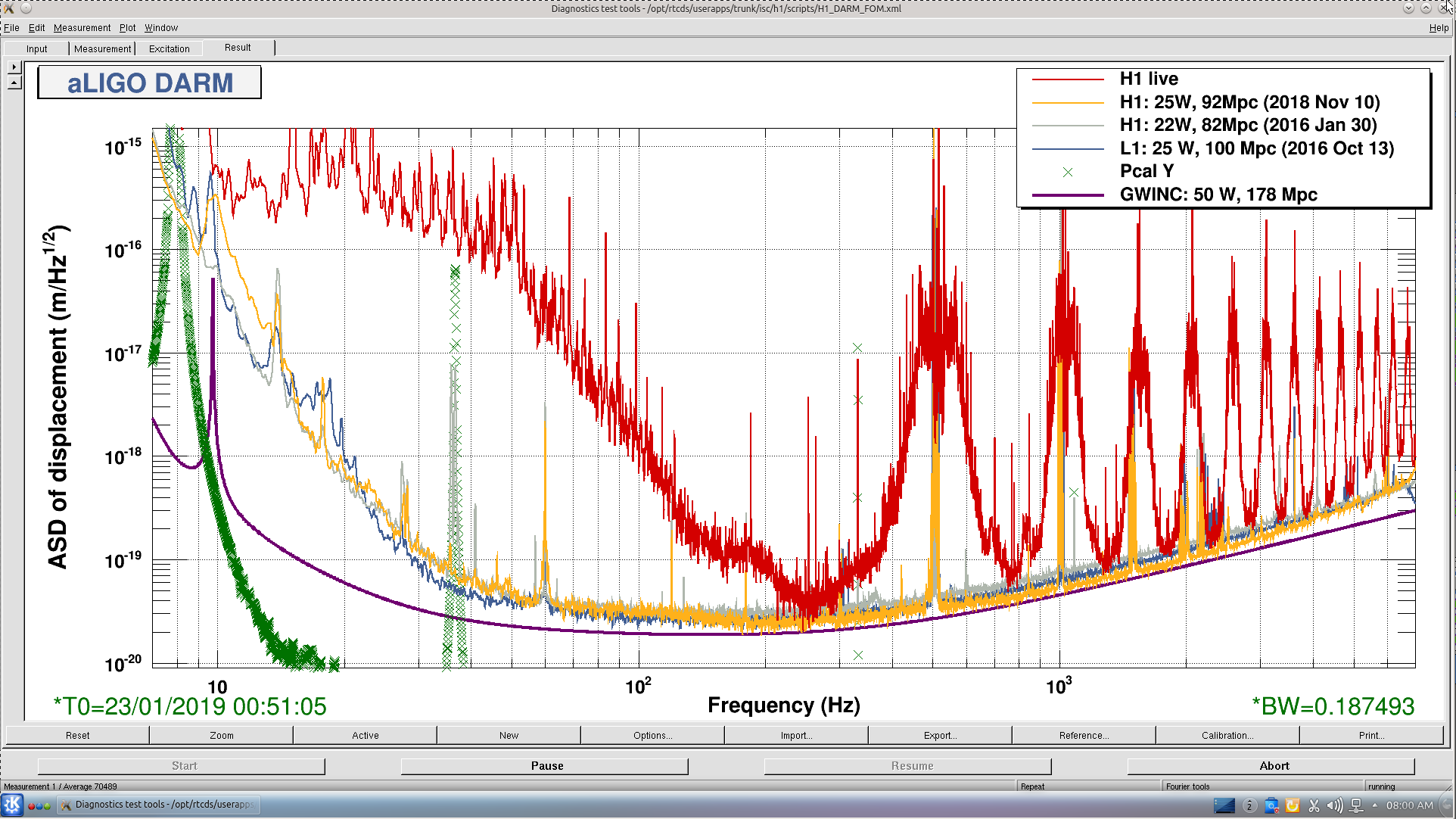
As is apparent in alog 46530, DARM calibration is off by about 10% at 100Hz, and it's hard to make comparison between now and Dec 2018 as is until a good calibration model is made.
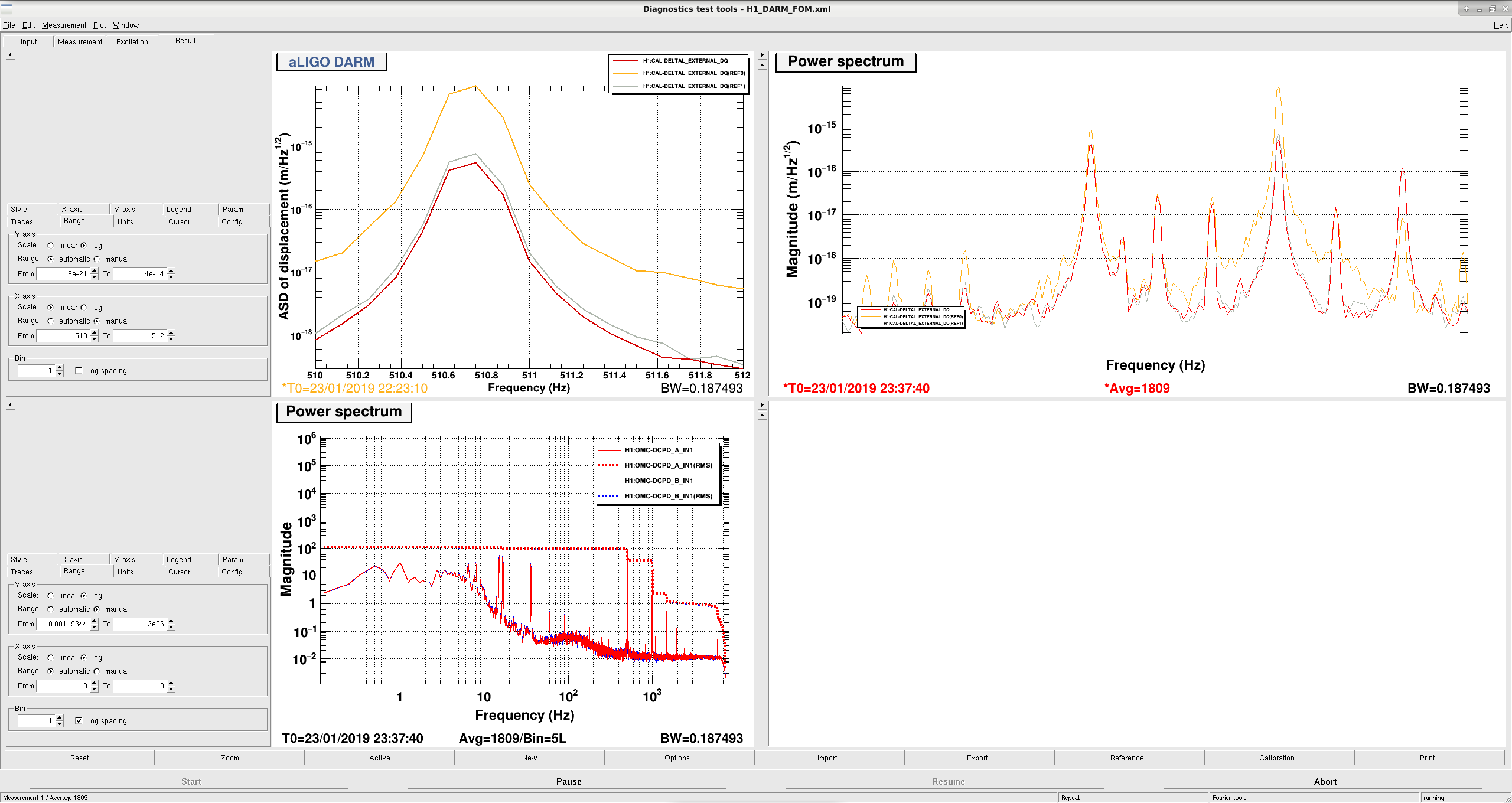
I made a FOM dtt template with two new calibrations, one starting December 08 2018 and the other Jan 01 2019.
/opt/rtcds/userapps/trunk/isc/h1/scripts/H1_DARM_FOM_PcalScanCorrected.xml
It should be OK for f>10Hz.
What I did:
From dtt, export CAL-DELTAL_EXTERNAL_DQ/CAL-PCALY_RX_PD_OUT_DQ transfer function of
/ligo/svncommon/CalSVN/aligocalibration/trunk/Runs/O3/H1/Measurements/FullIFOSensingTFs/
2019-01-16_H1_PCAL2DARM_TF_5t1100Hz_3min.xml
to a text file in /opt/rtcds/userapps/trunk/isc/h1/scripts/tempCalibForDtt20190123/.
Export the default TF calibration of the above transfer function to another text file.
Export the latest calibration of CAL-DELTAL_EXTERNAL_DQ dated 2018/10/4 22:28:48 from H1_DARM_FOM.xml to yet another text file.
Combine these three files and save into yet another file (newstopgapcal.txt) using
/opt/rtcds/userapps/trunk/isc/h1/scripts/tempCalibForDtt20190123/makeStopGapCalForDtt.m
Do the same for 2018-12-05_PCAL2DARM_TF_5t1100Hz_2min and save into yet another file (oldstopgapcal.txt).
Open DARM_FOM.xml using dtt.
Make a new calibration for H1:CAL_DELTAL_EXTERNAL_DQ at 2019 Jan 01 00:00:00.
Click "Trans. Func." tab, click "Edit", click "File" and "Open", load newstopgapcal.txt.
Repeat it, this time 2018 Dec 08 00:00:00, load oldstopgapcal.txt.
Save the dtt template as H1_DARM_FOM_PcalScanCorrected.xml
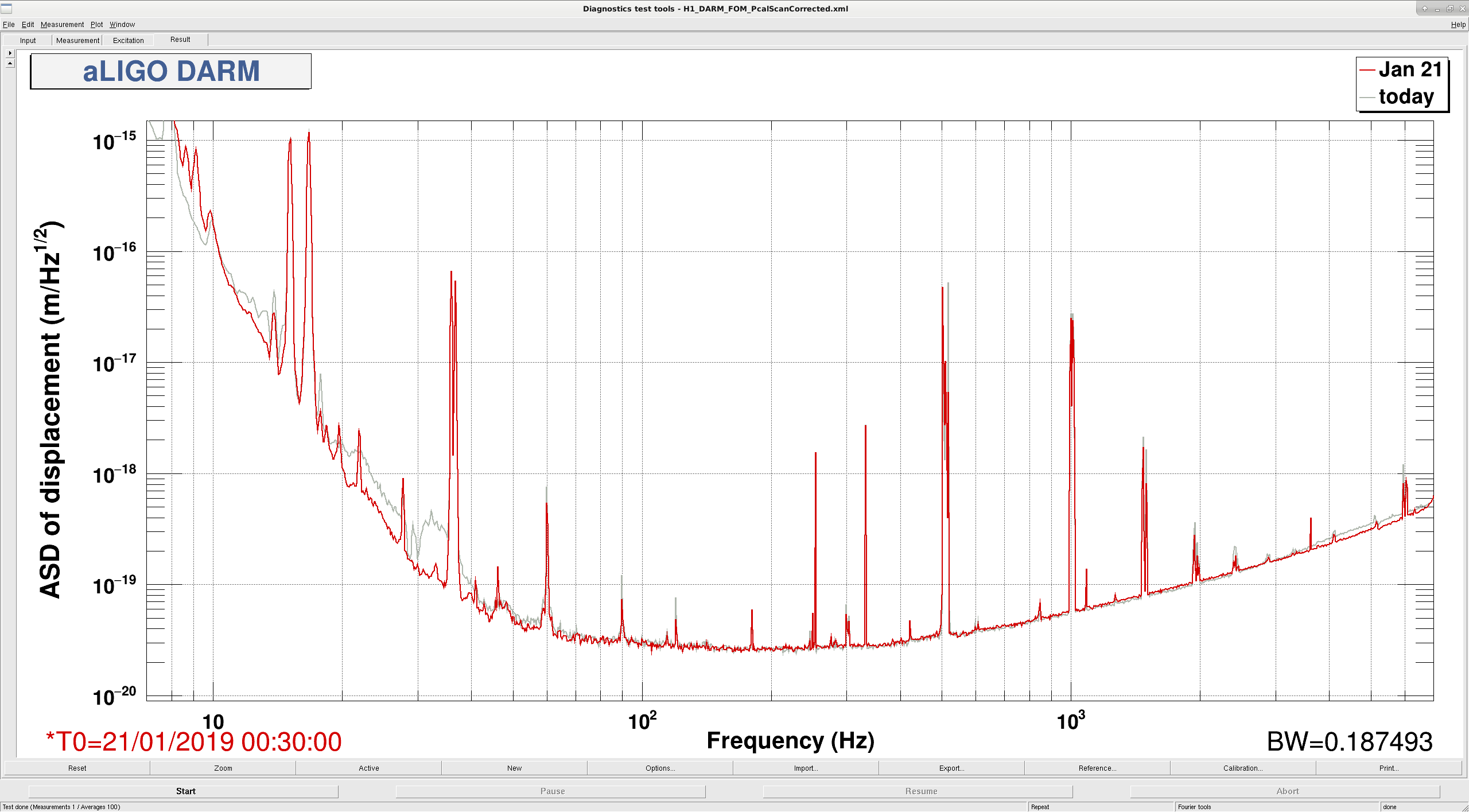
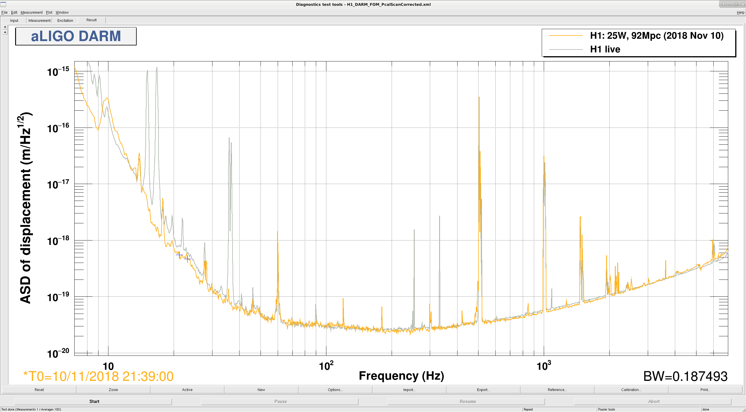
Here is a comparison of a lock from late last week (Jan 21 0:30 UTC) to the November reference using Ketia's template. The noise is generally similar, although if the November calibration was correct the shot noise has gotten slightly worse, when we increased the input power.
The november lock was Nov 11 at 21:39 UTC, the "live" lock is Jan 21 at 0:23 UTC. The power on the POP diode increased 22.7% from November to now, so the shot noise limited sensitivity should have improved by 10%. If this calibration comparison is really correct, we have instead lost sensitivity. It might be worth taking a closer look at the calibration lines in November to see how our optical gain compares.
I looked at the Nov 10th time that Sheila has in her DTT template (11th Nov as typed in the text of the log is a mis-type) and the 21st Jan time. The PSL injected power increased by 13% between these two times (26.7W -> 30.3W), and the POP_A_LF, and all 4 TR QPD sums all agree that the circulating power in the IFO increased by 10%. So, it's certainly true that the circulating power has increased. But, as Sheila points out in her plot, the shot noise region appears to have gotten worse. Sheila is doing a test right now to investigate this further.
J. Kissel I have installed updates to custom c-code and simulink library parts used by the h1calcs front-end model yesterday (2019-01-22) during maintenance (otherwise mentioned only briefly in Dave's maintenance-day summary LHO aLOG 46588). This update (described in more detail in LLO aLOG 42919) further improves the conditioning of the front-end constructed Time-Dependent Correction Factors (TDCFs), facilitating the eventual construction of a DELTA L EXTERNAL stream that is Compensated For Time Dependence (CFTD_DELTAL_EXTERNAL). I've got lots more work to do, though, before I'm confident enough to start applying TDCFs to CFTD_DELTAL_EXTERNAL.
J. Kissel I've processed the absolute actuator strength measurements for ETMX from 2019-01-14 (last week Monday just after reverting the bias voltage to "430 V"; see LHO aLOG 46414). The (unscaled**) answers are as follows: Actuator | Strength (N/ct) UIM | 7.933e-08 (+7.445e-11,-7.316e-11) or (+0.09385%,-0.09222%) PUM | 6.56e-10 (+3.021e-13,-3.022e-13) or (+0.04605%,-0.04607%) TST | 4.863e-12 (+1.719e-15,-1.71e-15) or (+0.03536%,-0.03517%) or in physical units (i.e. removing all of the well-known quantities in the electronics chain and leaving only the fundamental force-per-fundamental-drive-unit): Actuator | Strength UIM | 1.69 (N/A) PUM | 0.03203 (N/A) TST | 4.554e-11 (N/V^2) where N is Newtons of force, ct is 18-bit DAC counts *, A is current in the coil of the OSEM, and V^2 -- assuming a requested bias voltage of 9.3 V_DAC = (40 V_ESD/V_DAC * 9.3 V_DAC) V_ESD = 372 V_ESD. * Remember -- ETMX's ESD electronics chain is driven by a 20 bit DAC, changed out in Oct 2018 (see LHO aLOG 44905). However, we've compensated for this swap with a factor of 4.0 in the ESDOUTF filters of ETMX, down stream of the excitation point of the measurement, and thus the "count" drive is still an 18-bit DAC count. However, (a) ** These measurements were taken with the PCAL Y RX PD used as absolute reference, and were taken before the PCALY RX PD absolute scale was updated (see LHO aLOG 46449). So these answers need to be scaled: PCAL OLD DARM ERR H_oldref = -------- * -------- DARM ERR SUS EXC PCAL NEW H_scaled = -------- * H_oldref PCAL OLD where (new/old) = 0.9759 for PCALY RX PD as reported in LHO:46449. (b) It's dreadfully obvious from the measurement that our model has plenty of frequency-dependent systematic error. I also know the following: (i) We have not updated the dynamical model of the QUAD to include updated known-to-exist, non-"falls as simple f^(2*istage)," high-frequency dynamics . Were still using the old O2 dynamical model which has ETMY's (former) violin mode frequencies ("the Shapiro Effect" impacting primarily the PUM stage, see LHO aLOG 16057), and does not include the UIM stage actuator's funky resonances (see LHO aLOG 38295). (ii) We have not measured, and thus not well-compensated, any stage of SUS ETMX's driver electronics. We're still using the "off-the-shelf," "same compensation for each quadrant" compensation. As such, I've restricted the frequency region of the fit to where there is no (OK, much less) frequency-dependence in the residual between model and measurement. This is not necessarily the right thing to do, but we won't know until we clean up the known causes of frequency dependence mentioned just above. The PCAL RX PD channel calibration has been updated since this measurement, I'm actively working on getting an updated dynamical model, and I'll measure the coil/ESD driver transfer functions next Tuesday. But if we must update the front-end calibration sooner than we can get a new set of measurements (after updating the coil/ESD driver compensation) then we could use these scaled values: The (scaled) answers are as follows: Actuator | Scaled Strength (N/ct) UIM | 7.7418e-08 PUM | 6.4019e-10 TST | 4.7458e-12 or in physical units: Actuator | Strength UIM | 1.6493 (N/A) PUM | 0.031258 (N/A) TST | 4.4442e-11 (N/V^2) I have not updated anything in the front-end calibration. I'm going to process the sensing function measurement from 2019-01-19 (LHO:46530) and confirm that I can re-construct the DARM open loop gain transfer function well with these actuator numbers, and then I'll push an update to the calibration into the front-end. See comment to this log describing the details of *how* I processed these measurements with the new pyDARM infrastructure.
J. Kissel
I've processed the measurements which live in
/ligo/svncommon/CalSVN/aligocalibration/trunk/Runs/O3/H1/Measurements/FullIFOActuationTFs/
with the following script:
/ligo/svncommon/CalSVN/aligocalibration/trunk/Runs/O3/H1/Scripts/FullIFOActuationTFs/process_actuationmeas_20190114.py
which I updated from a similar 2018-12-05 example [from LHO:45726 when I was analyzing only ETMX] in order to
- install frequency limits on the fitting without restricting the data
- loop over multiple stages
and in the process reformatted a bunch of hard-coded stuff from from throughout the script and put it at the top for future ease of reuse.
That script uses a new loop model parameter file
/ligo/svncommon/CalSVN/aligocalibration/trunk/Runs/O3/H1/params/modelparams_H1_20190114.py
which I had to update from the 2018-12-05 model [again from LHO:45726] in order to
- account for the all-ETMX DARM drive configuration we're no using,
and in the process added a parameter for converting the sensing function from units of (DARM IN1 ct) / (DELTAL m) to (OMC DCPD Current mA) / (DELTAL m) because of other unrelated requests.
It also uses the pyDARM function library
/ligo/svncommon/CalSVN/aligocalibration/trunk/Common/pyDARM/src/actuation.py
which had to be updated to
- collect all of the advancements in sign-science solutions hinted at in LLO:42786
- use frequency limits on the fitting without restricting the data
All of the above have been committed to the CalSVN repo in the above described locations.
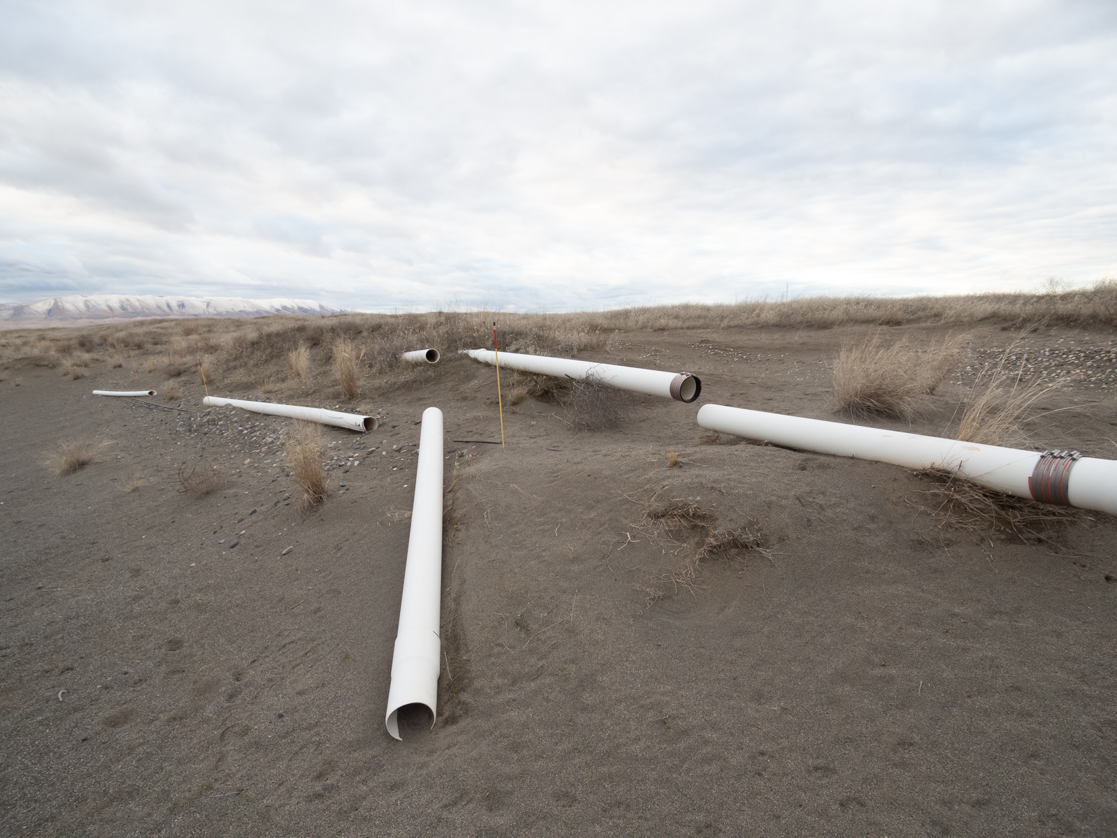
Yesterday ALSY became glitchy again while it was raining. Wild guess in the control room was that somehow it might have to do with the known fact that a part of the fibers outside was exposed due to erosion of the dirt covering the cables.
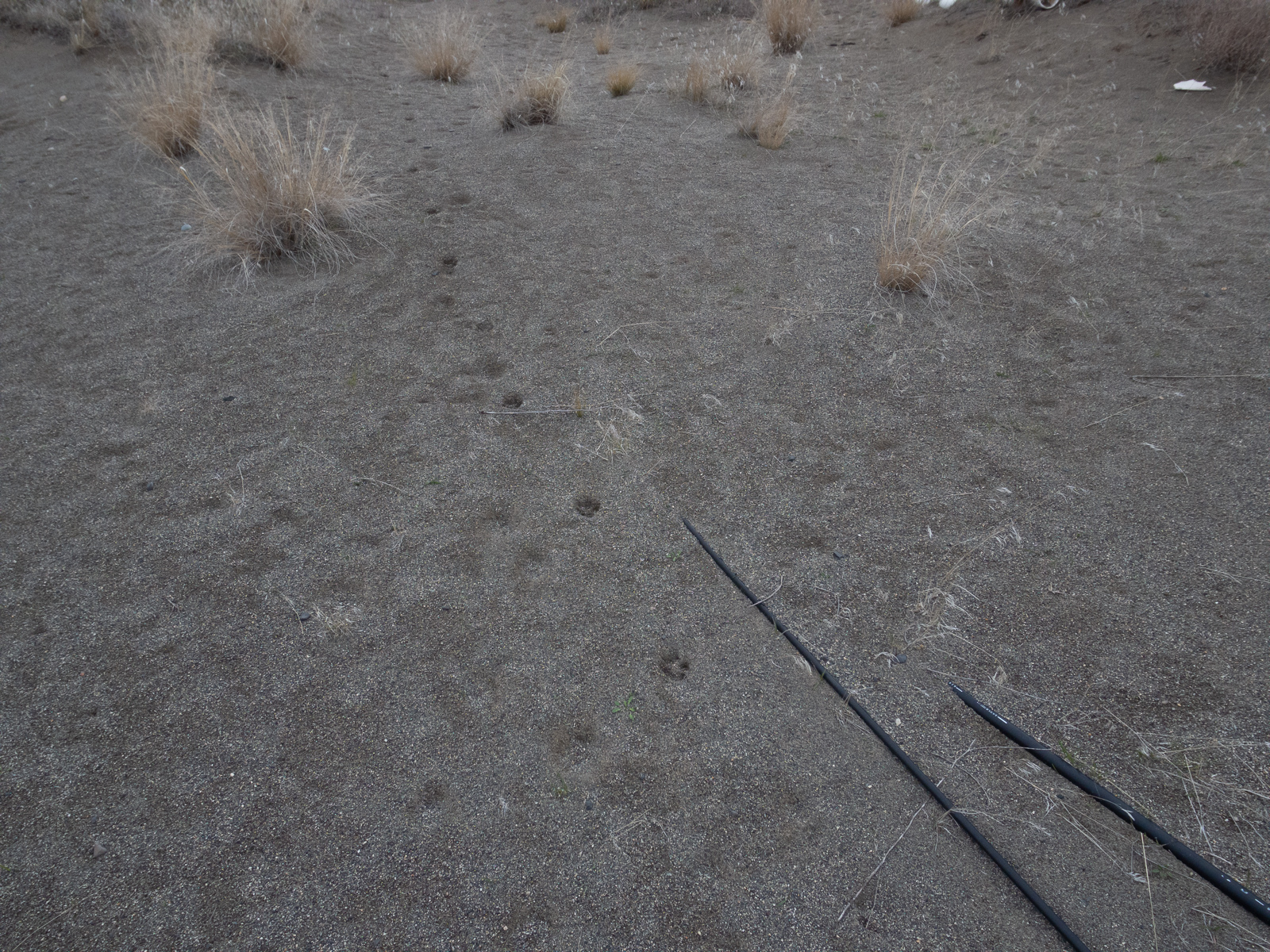
Since I have never seen how the ALSY fibers were exposed or for that matter supposed to be buried, I took a mini hike to mid station using off road path. Attached are the pictures of the place where I was able to see some cable exposed, maybe 20 or 30 meters from the MY toward the corner. This is the only place where I was able to see bare cables between the corner and MY though there were many places where white PVC was exposed.
Broken PVC pipe segments were on top of the cables, and there were many fresh-looking signs of animal traffic along and across the fiber.
I can imagine that raindrops or small rocks hitting the cable, or PVC rolling on top of it when windy, or animals walking on top of it might cause some kind of glitches, assuming that one of these is ALS fiber (which I'm not sure about).
Jenne and I did some violin mode damping for ETMY which had some tall peaks at around 510.715 Hz. We looked at the FM2 and FM3 filter and found that they were not at +-60 degree phase. Hence we made some new filters that are actually at +-60 degree phase, and loaded them in the Gaurdian. Also, we detected some old 1kHz filter (from 02), which we deleted. Finally we applied a gain of 0.4 (in steps starting from 0.1), resulting in damping of the excitation which is visible in the change of the peaks (almost by an order of magnitude).
Note that none of these changes are in guardian. We left the old (not actually +/-60 deg) filters in place in ETMY Mode1, so that the guardian will turn on damping for this mode with the previously-good settings, until we have validated that some new settings with the new filters are good.
Separately, it seems a bit as though the best damping settings seem to change as a function of peak height. I accidentally rang this mode up quite a bit earlier today, using positive gain and no phase filters. However, when Rahul and I were looking at it later in the afternoon (after I accidentally rang it up more while trying other settings...), we had good success with no phase filters. Presumably this is due to some confusion with the ~12 mHz higher ETMY Mode6 peak, although it's always hard to tell, since it's hard to have the patience to look at a fine enough spectrum that can distinguish the 2 modes...
Hi Raul, Jenne
Please have a look at my entry from yesterday on this exact issue you are dealing with here, and actually on all violin modes at LHO.
https://alog.ligo-wa.caltech.edu/aLOG/index.php?callRep=46597
[Sheila, Jenne]
About the 1.1 Hz noise in PRCL:
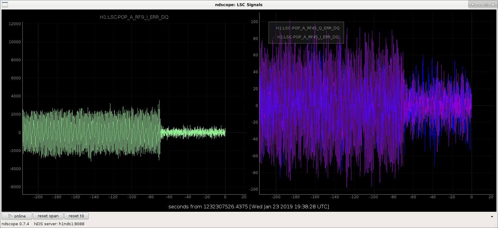
Although the ISI suspoint indicates about 10 nm/rt Hz at 1.1 Hz for PR2 longitudinal, in the PRCL calibrated spectrum, we see about 100 nm/rt Hz. The residual 1.1 Hz was dominating PRCL, SRCL and MICH. The attached screenshot shows the error signal time series when we engaged the resG.
We initially tried adding this resG when we reach full lock but before the ASC is on, it made the ASC and LSC unstable, so we moved it to just before DC readout instead, which has been fine.
Other locking notes from this evening:
About the extra noise in today's lock: it seems to be Y2L coupling, see alog coming soon.