TITLE: 01/23 Day Shift: 16:00-00:00 UTC (08:00-16:00 PST), all times posted in UTC
STATE of H1: Commissioning
INCOMING OPERATOR: None
SHIFT SUMMARY: Commissioning continues. Currently locked for almost 4 hours.
LOG:
1530 Chris S to and from EY supply fan room
1625 Karen to Opt. Lab
1650 Karen out
1653 Peter to Opt. Lab
1658 Nutsinee to ISCT6
1919 Nutsinee out
1944 Nutsinee to ISCT6
2001 Karen Rolling up the OSB receiving door
2006 Nutsinee out
2200 Nutsinee to ISCT6
2303 Chris done for the day
2321 Kyle to MY
2333 Kara to EY VEA
2335 Nutsinee out
2357 Kyle back
FAMIS10493
No water was added to either chiller, both were full and checked yesterday. Filter looked to be free of debris.
FAMIS8088
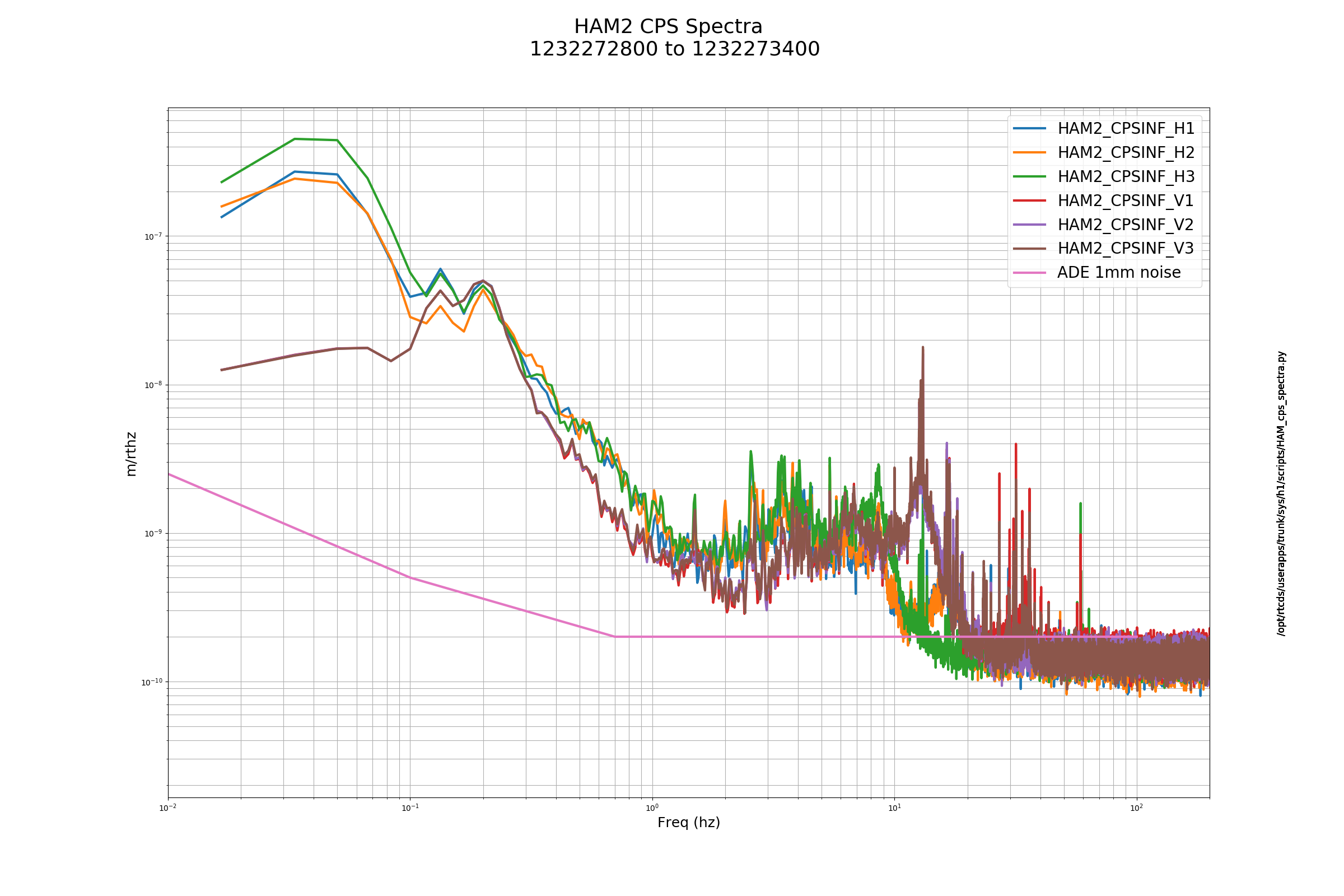
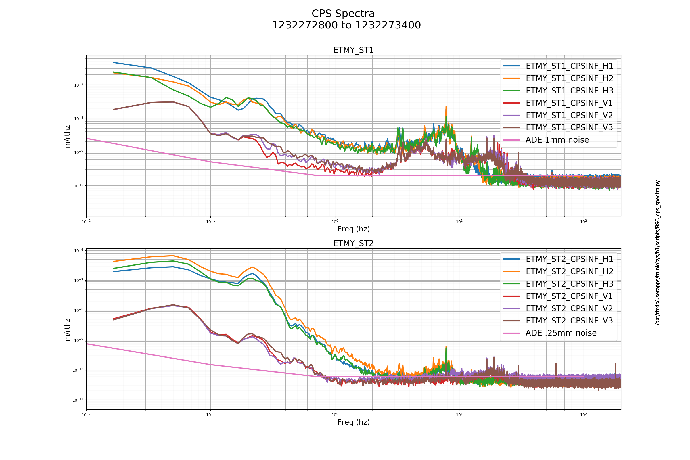
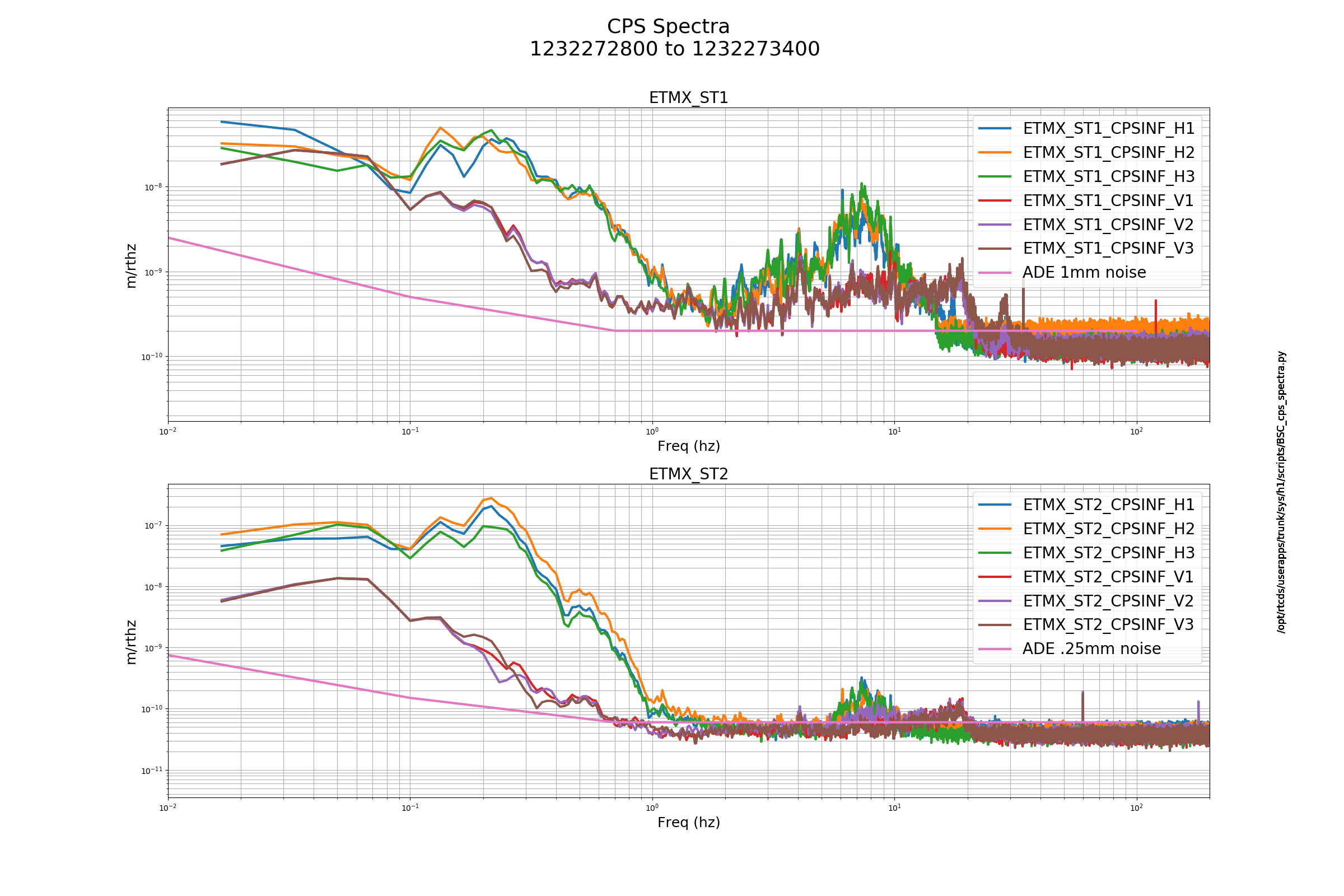
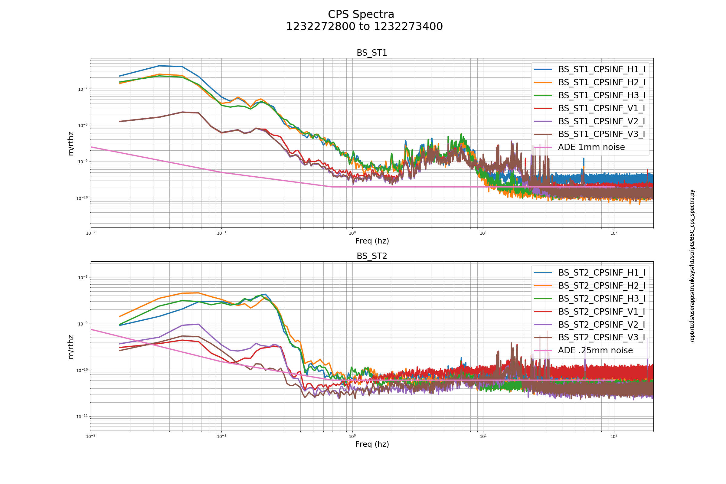
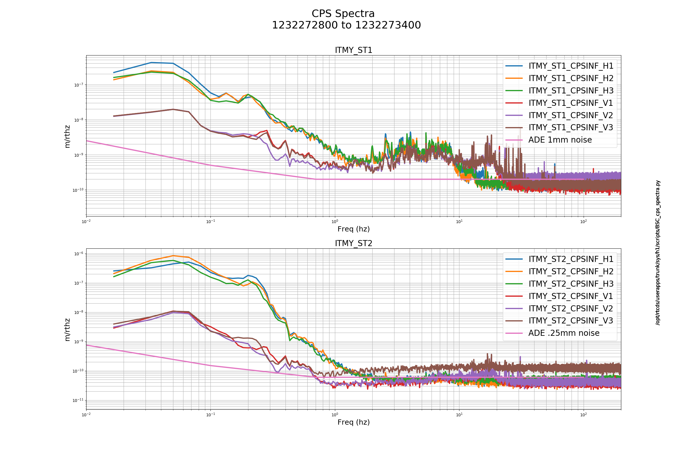
ITMY ST2 V3 is reported as high. Seems that it is elevated above the others.
I spent more time looking at the HAM3 ISI yesterday, trying to figure out the source of the 1.1 hz peak. I don't have a fix, or even an improvement, but I think the V2 GS13 is probably bad.
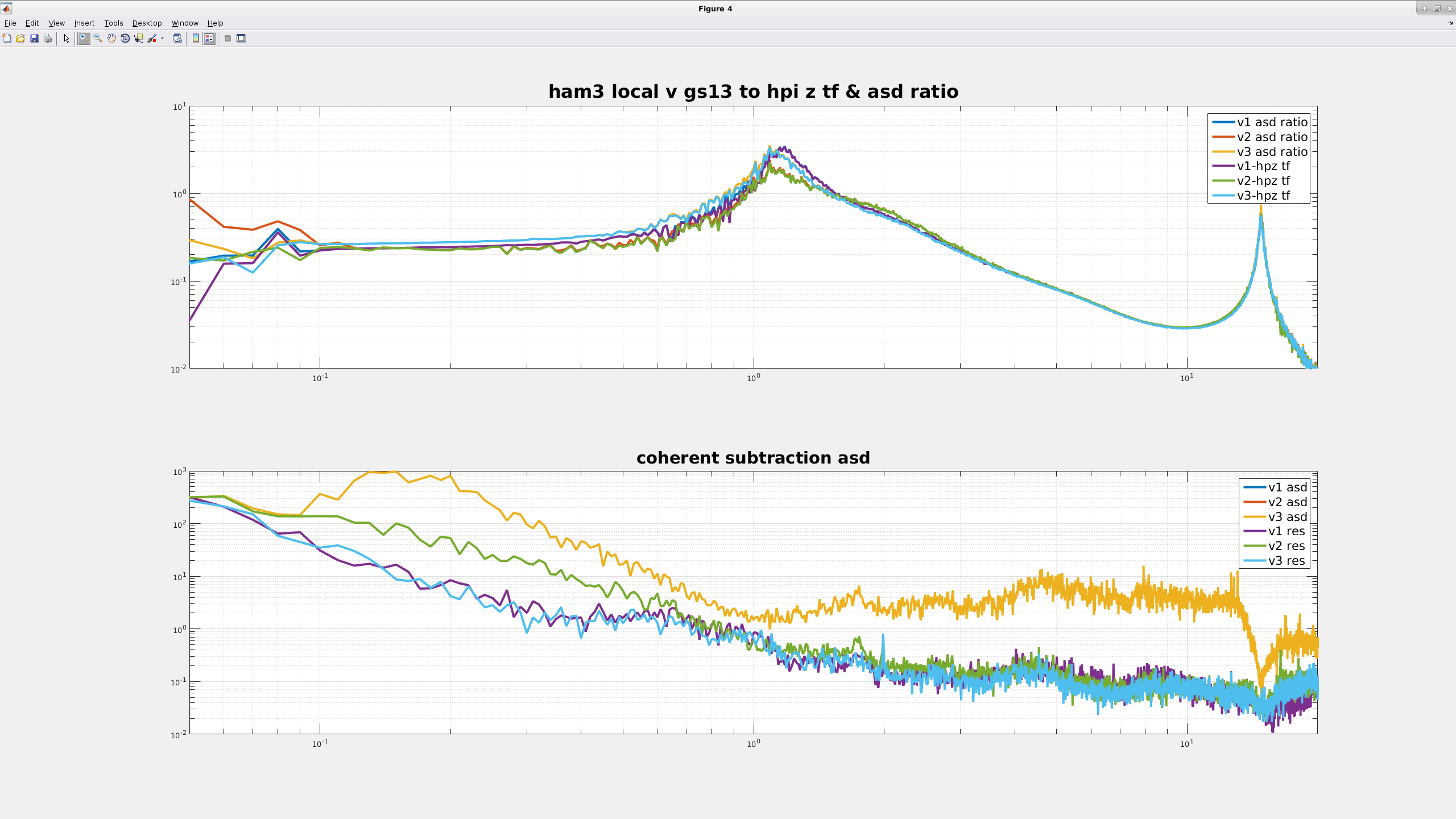
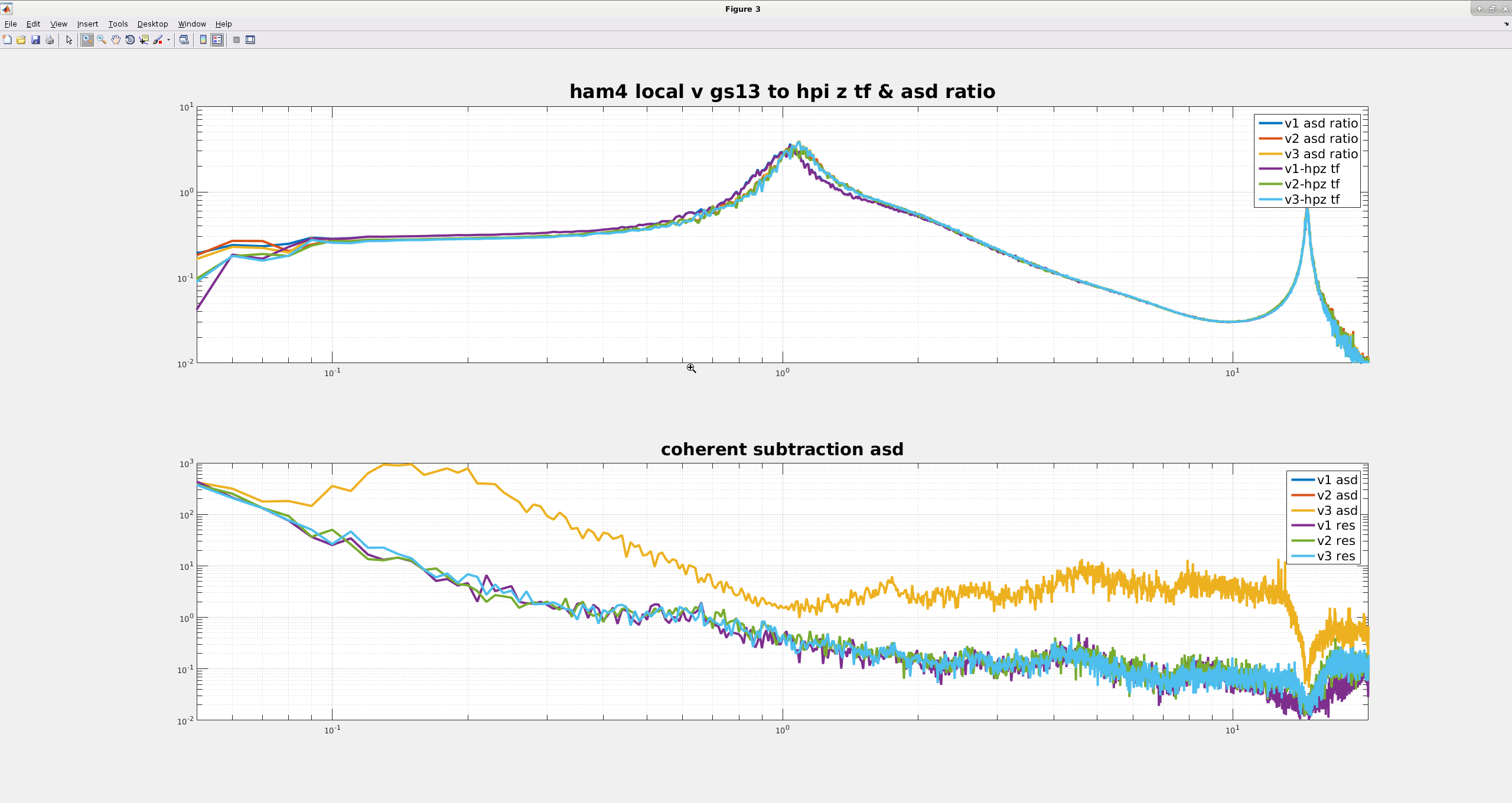
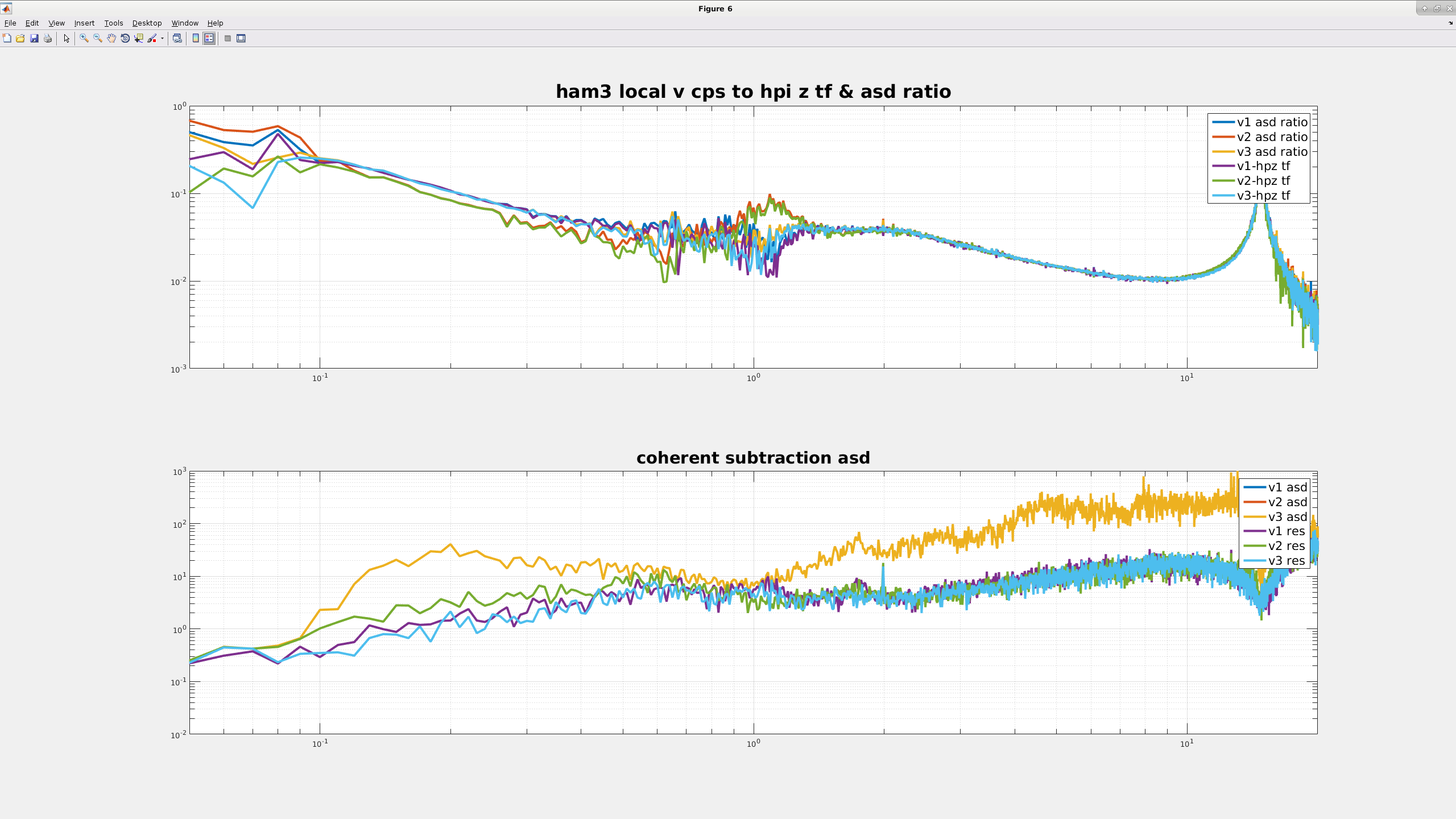
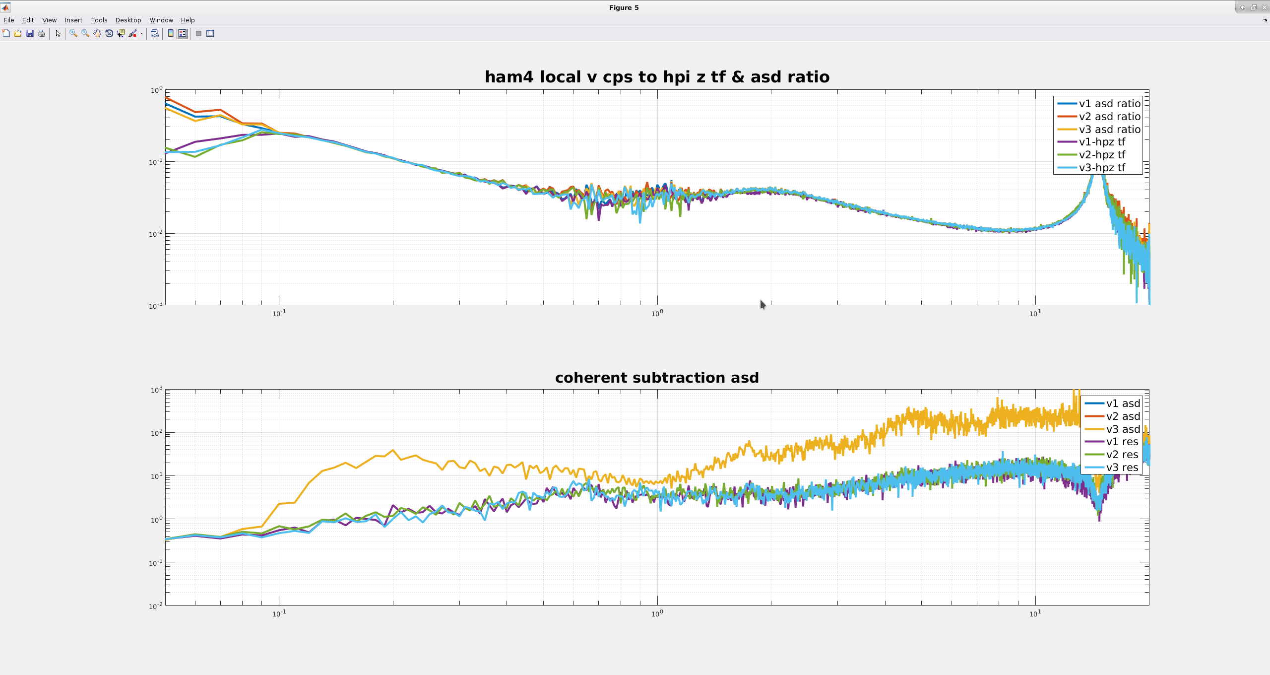
The top plots on my first two attached images compare the HAM3 & 4 HEPI L4C Z to local ISI GS13 asd ratios and transfer functions, HAM3 in the first image, HAM4 for the second. For all of these plots, both ISI's were damped only, so only the GS13s were in loop at the time. For both chambers, it's hard to see, but the HEPI Z to ISI V1/V2/V3 GS13 asd ratios lie right on top of the equivalent transfer functions. If I remember what Jeff said right, this means there are no significant non-linear cross-couplings in the GS13s. Note, also that the HAM4 tfs all look about the same, but V2 for HAM3 has a lower Q and generally doesn't look quite as similar to the other two HAM3 sensors, just like Keita found a couple months ago.
The bottom plot for the first two images are asds for the HAM3 and HAM4 local GS13s. The gold line on each lower plot is actually 3 lines, the asds for each of the individual GS13s on the table are very similar over this frequency range. The light blue, dark blue and green (?) traces are are the residual asds after using MCCS2 in Matlab to subtract all the coherent HEPI Z noise from each GS13. For HAM4, the residuals for all 3 GS13s look pretty similar, but for HAM3 there is quite a bit of extra noise in the residual for the V2 sensor below 1 hz. I'm not sure where it's coming from, but I could believe that it's something like the mass in the seismometer is a little sticky, or there's something wrong with the flexures.
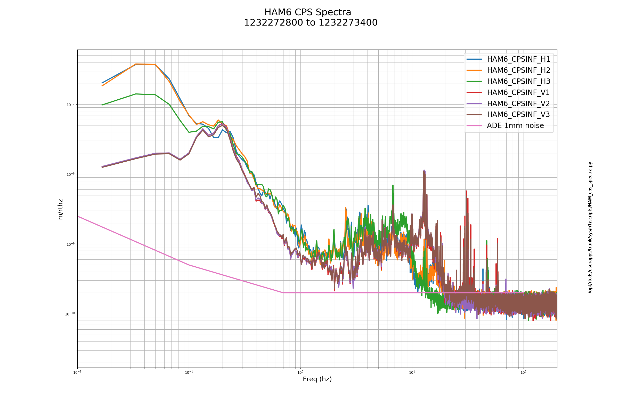
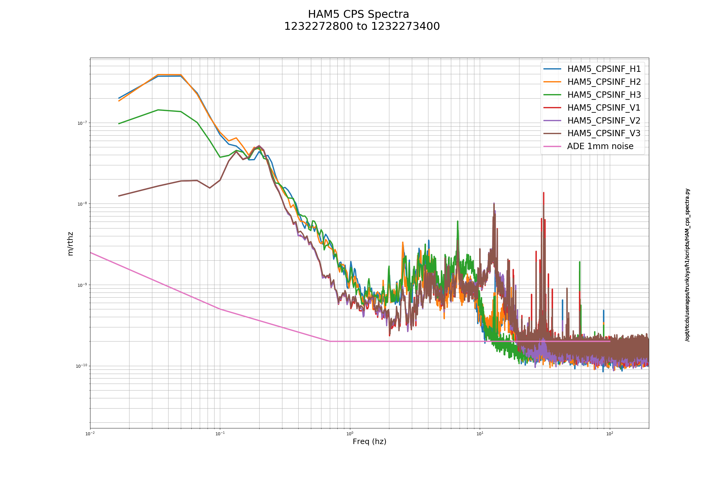
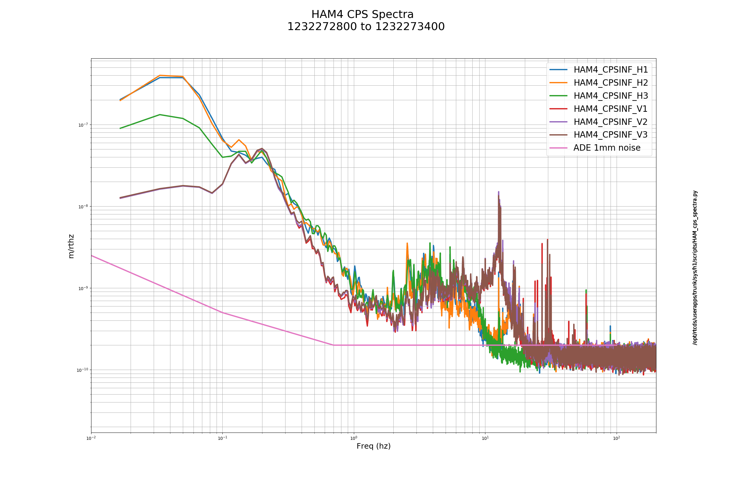
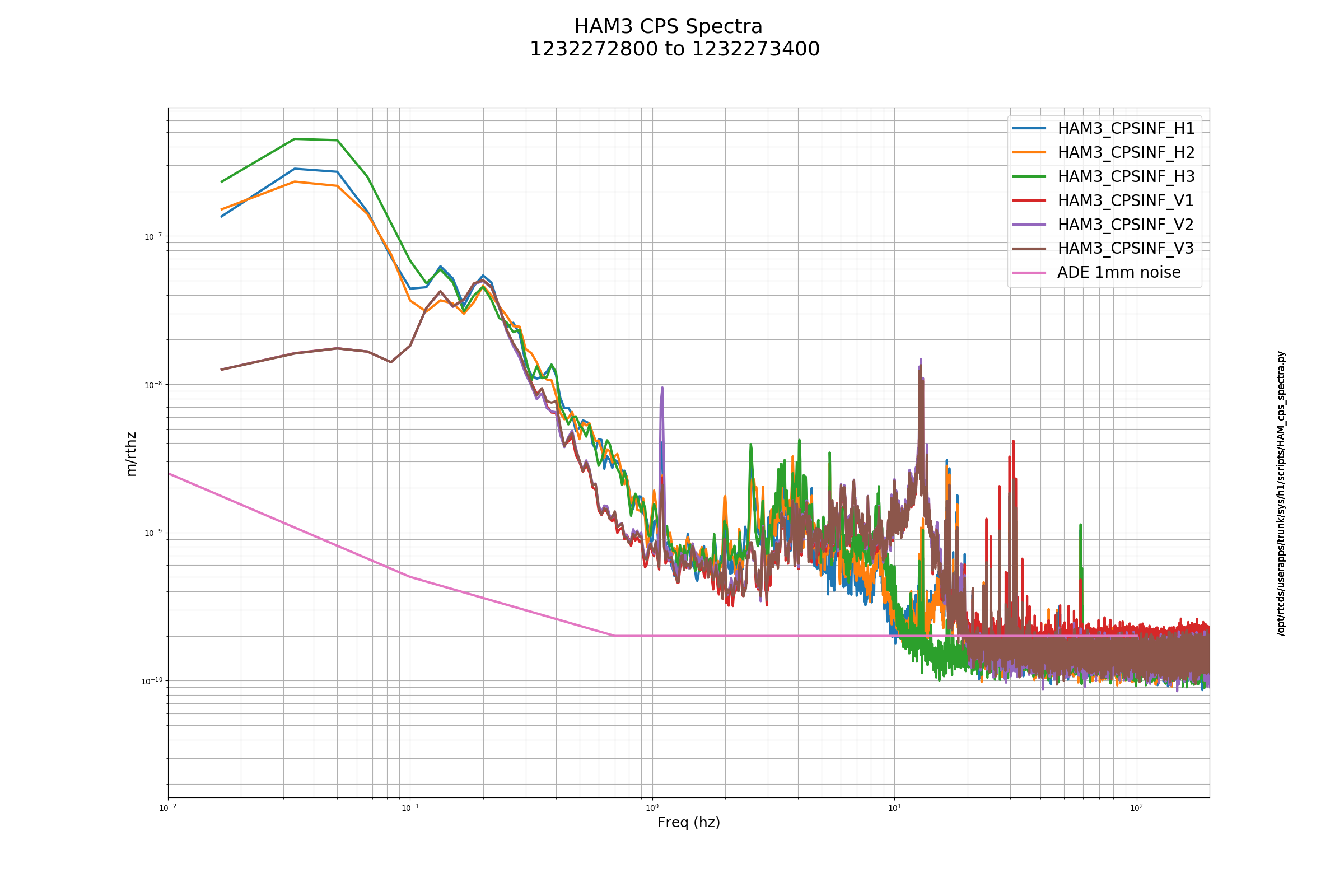
The third and fourth images are similar to the first two, but use the local CPS on HAM3 & 4 instead of the GS13s. The top plots on these images are similar to the first two, the asd ratios mostly lie right on top of the transfer, though match up is not quite as good at 1hz. I think this is probably because the ISIs, GS13s and L4Cs all have modes around 1 hz, there's a lot of stuff happening there.
The bottom plots on the third and fourth images are again the MCCS2 coherent subtraction of the HEPI L4Cs from the ISI local V1/V2/V3 CPS. Again, HAM4 all of the sensors asds and residuals all look pretty similar and the asds for the HAM3 sensors all look the same, but the residuals for the V2 sensor show more noise below 1 hz. I think this is because the damping loops are impressing the extra noise from the V2 GS13 on the V2 CPS. I plan on repeating this measurement for a period when the all of the controls are off, to see if the V2 CPS residual changes.
Some other tests I tried, but generally didn't keep good spectra of:
Moving sensor correction to HAM3 HEPI - no change to the 1.1hz peak, but good isolation at the microseism. Adding an IPS & L4C blend to the HEPI Z loop also didn't improve the peak, but the HEPI Z loop is, I think, only 2 hz ugf, maybe the gain of the Z loop can be pushed up.
Pushing RX/RY/Z blends around, this affects the frequency of the peak some, but doesn't improve the height much.
Turning off the ISI Z loop makes the peak go away. If the 1-10hz Z motion isn't that important, maybe we could run this way. Worth looking at more.
Running the Z isolation loop with just the V1 & V3 GS13s. Again, no improvement, but 4 out of the 5 remaining loops still use the V2 sensor. The contribution is small for the X/Y loops, but RX and RY need the V2 GS13. This is worth looking at a bit more, Brian Lantz has a DCC document about why we shouldn't remove the sensor completely.
[Sheila, Jenne]
About the 1.1 Hz noise in PRCL:
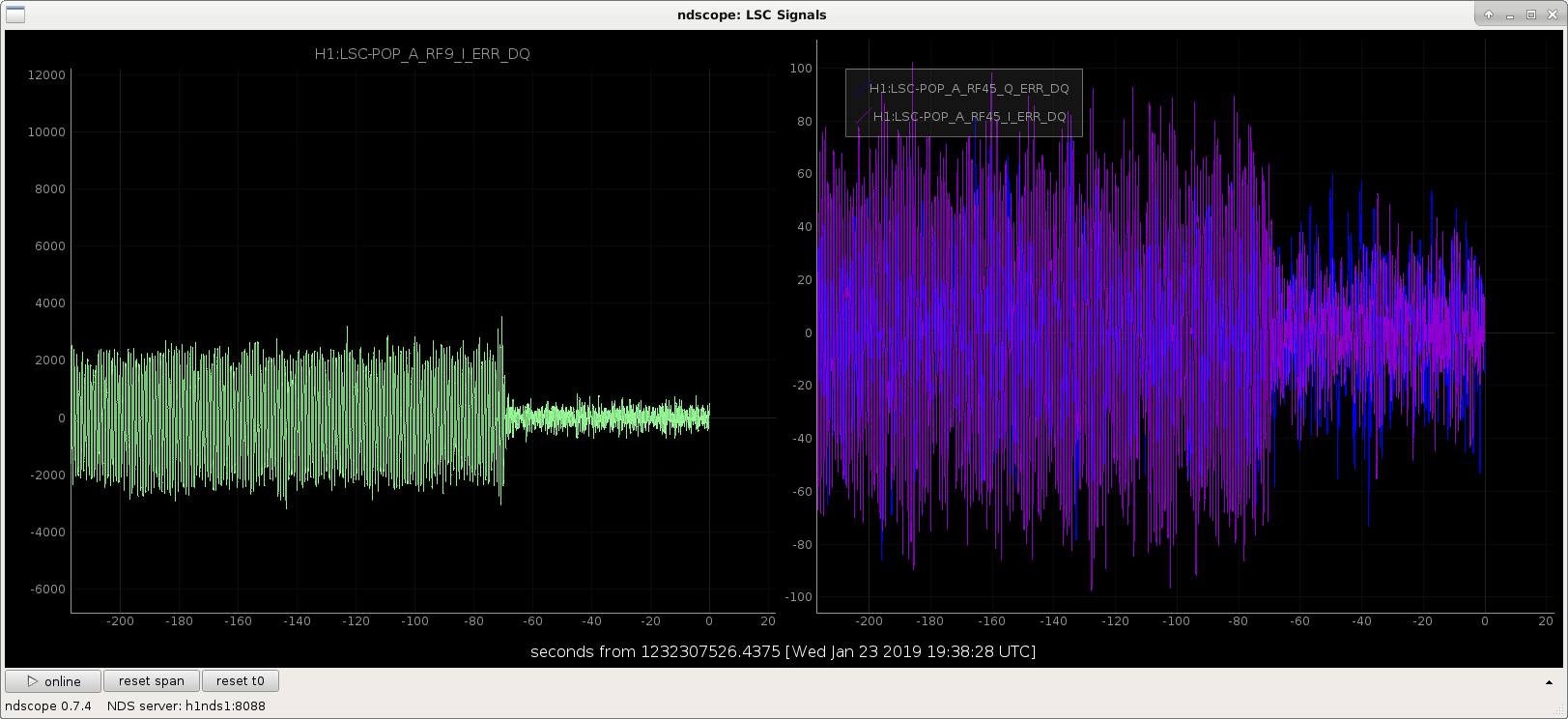
Although the ISI suspoint indicates about 10 nm/rt Hz at 1.1 Hz for PR2 longitudinal, in the PRCL calibrated spectrum, we see about 100 nm/rt Hz. The residual 1.1 Hz was dominating PRCL, SRCL and MICH. The attached screenshot shows the error signal time series when we engaged the resG.
We initially tried adding this resG when we reach full lock but before the ASC is on, it made the ASC and LSC unstable, so we moved it to just before DC readout instead, which has been fine.
Other locking notes from this evening:
About the extra noise in today's lock: it seems to be Y2L coupling, see alog coming soon.
I have been looking at the in-vacum violin modes at LHO for the first 8 harmonics and thought it could be useful to upload the frequencies here for current works on setting up the active dampers.
The data used to identify these frequencies is the recent 15 hours long stretch of low noise detector state on the 3rd January at 04:00:00
Each harmonic has the 32 violin modes identified (with a couple of missing ones at the higher order harmonics). 8 split modes per suspension and 4 QUAD suspensions.
These frequencies will be added to the LHO violin mode table which also include the 'Historical data' of the violin mode harmonics before the May 2018 swap of the ETMX, ETMY and ITMX. Comparing new and old values shows that the non replaced ITMY has also changed its violin mode frequencies.
The next step will be to measure the new Q's of these violin modes and grouping violin modes of all harmonics per test mass without exciting the suspension, as done during O2.
NOTE: On the LHO violin mode table above there is a comment on the MODE 6 filter for ETMY: ' this doesn't seem to damp well, is it really an ETMY mode?'
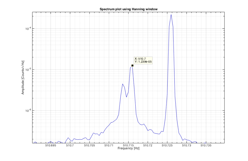
The reason for the apparent inefficiency of this filter is that there are at least 2 modes in that region, potentially 3 modes as shown next on a high resolution spectrum during the time when the filter was active (I think):

TITLE: 01/23 Day Shift: 16:00-00:00 UTC (08:00-16:00 PST), all times posted in UTC
STATE of H1: Commissioning
OUTGOING OPERATOR: None
CURRENT ENVIRONMENT:
Wind: 10mph Gusts, 8mph 5min avg
Primary useism: 0.03 μm/s
Secondary useism: 0.31 μm/s
QUICK SUMMARY: Jenne already working a locking interferometer. A few FOMs needed restarting, as usual. Microseism is staying down and wind is below 20mph.
Sheila Georgia Craig Koji
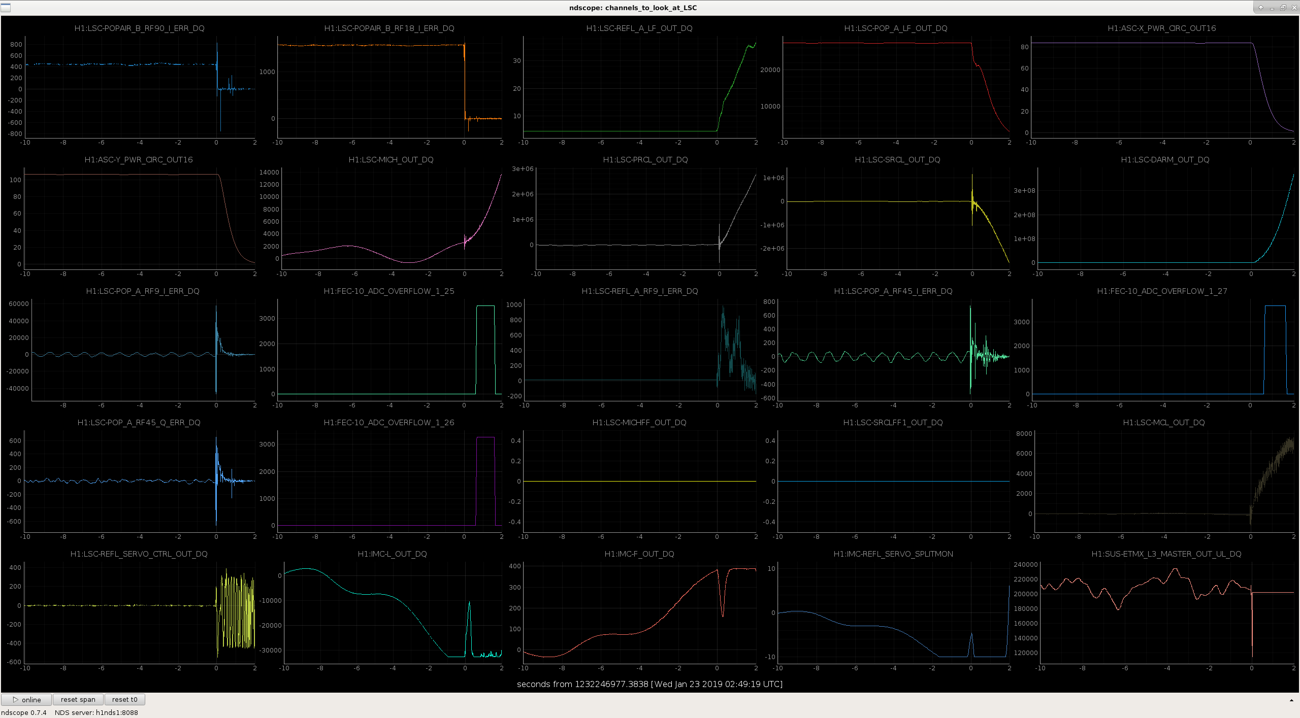
IMC board saturation:
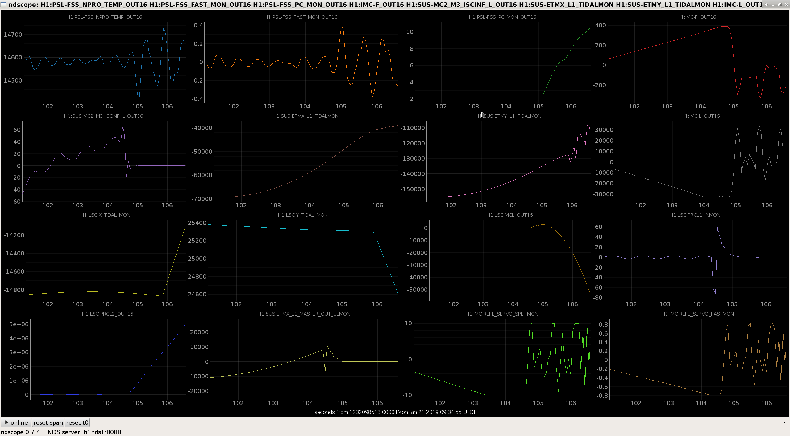
We had trouble staying locked for more than 10-20 minutes after powering up today, which turned out to be because of saturations in the IMC common mode board. The attached screenshot shows IMC-REFL_SERVO_SPLITMON (which is a beckhoff channel calibrated into volts right after the IMC boosts) hitting 10Vs, IMC-L hitting it's ADC limit fractions of a second later (which doesn't matter since it's not in loop). Georgia and Craig are working on redistributing the analog gains to avoid this.
BS ST2 isolation glitches causing DRMI locklosses:
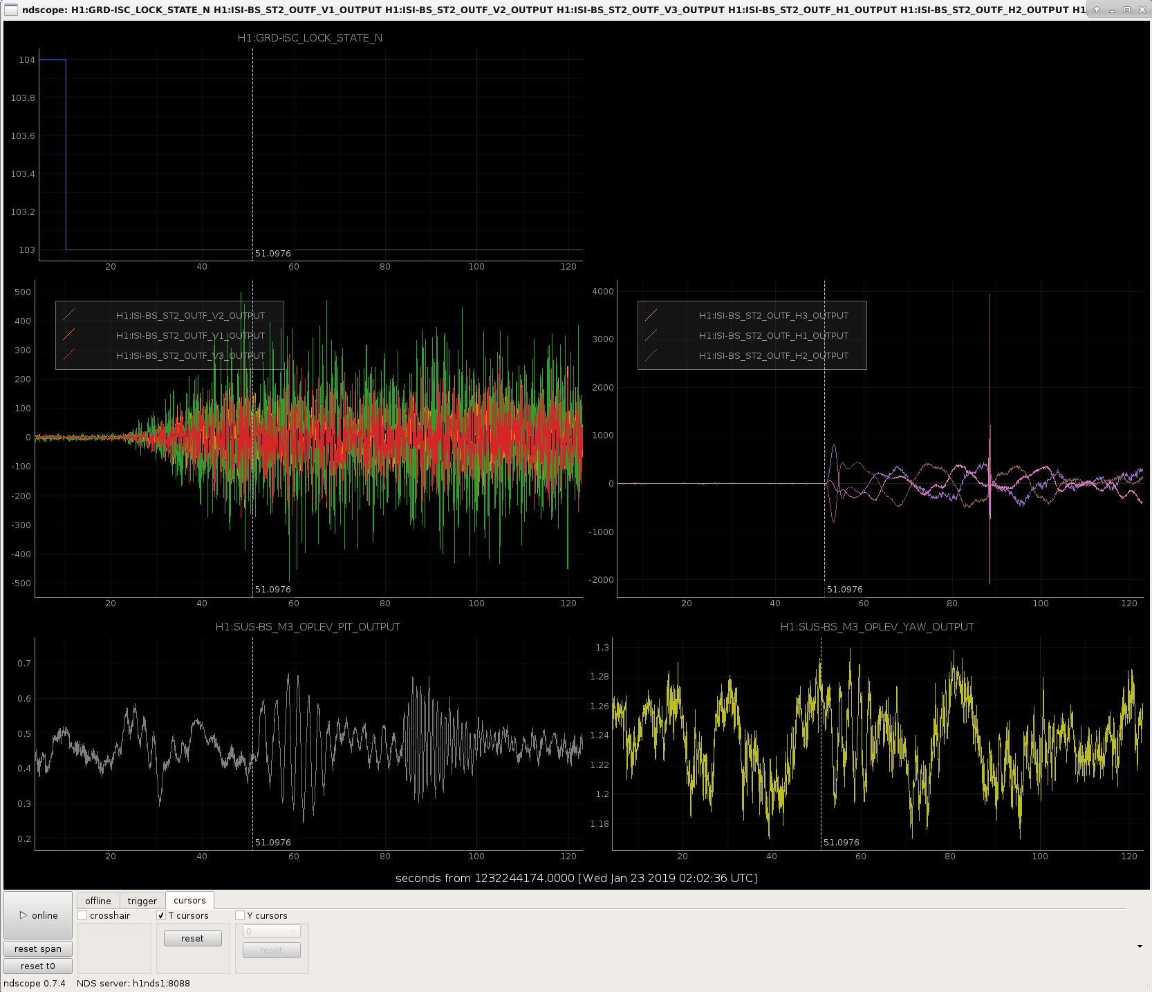
We had some difficulty keeping DRMI locked after it acquired tonight. We went through the next several guardian steps, and found that the big transient glitches that have been causing us a lot of grief are from engaging the beamsplitter ISI ST2 isolation. Georgia saw a transient on the optical lever when the only thing that was happening was that the BS ISI was isolating. It should be possible to recreate this without locking anything. For now we have removed the BS ST2 isolation from the main guardian path.
DRMI ASC:
Georgia also found that we had DRMI locklosses when the SRCL mode hopping avoidance offset gets turned off in ZERO_3F offsets. We decided to try engaging the DRMI ASC to avoid this, which was fairly easy. We changed some of the filter states (PRC1 and PRC2) to match what we are using in full lock, changed the SRM sensor to AS A 72Q (it was a combination of A+B), and increased the gains in several of the loops. Once we had all the loops engaged Georgia tuned the POP A offset to increase the POP18 build up to ~63 counts. We have tested the engagement with the gaurdian twice, it seems fine.
Lownoise ASC:
We tried to go through lownoise ASC once, but lost lock due to the IMC saturation, not related to the ASC changes we were making. I've edited the gaurdian to not reduced the DHARD P gain anymore, and to engage the less aggresive DHARD low pass based on the measurement that Craig and Koji made last night (46559), this hasn't been tested yet.
Maybe not super important since we've not been using the POP QPD for full-lock ASC recently, but the change in ASC-POP_A offsets for DRMI ASC engagement was:
| old | new | |
| PIT_OFFSET | -0.52 | -0.9 |
| YAW_OFFSET | -0.03 | 0.4 |
Also attaching a screenshot of the effect of turning on beam splitter ISI stage 2. This happens in ISC_LOCK guardian state number 104, top plot. When the H1, H2, and H3 outputs are engaged (middle plots) there is a big kick which is seen on the beamsplitter oplev (bottom plots), mostly in pitch. In this particular lock we survived the kick to the beamsplitter but this is not always the case.
I adjusted the MC board gains to take 6 dB of gain from IMC_IN1GAIN and IMC_IN2GAIN, and put it on IMC_FASTGAIN.
I also adjusted the ISC_library.IMC_power_adjust() function to take in a some scaler that allows the user to set the IMC_FASTGAIN setting for 2 watts. This scaler is now set to 6 dB, where is formerly was 0 dB by default since the variable didn't exist.
I then made adjustments to ALS_COMM and CARM_TO_ANALOG so that we were able to get through guardian with no overall gain change.
The final gain settings at full lock with 30 W should be:
Channel Slider Value [dB]
---------------------------------------------------
H1:LSC-REFL_SUM_A_IN2GAIN 8
H1:LSC-REFL_SERVO_IN1GAIN 6
H1:LSC-REFL_SERVO_FASTGAIN 16
H1:LSC-MCL_GAIN 16.9 [magnitude]
H1:IMC-REFL_SERVO_IN1GAIN 22
H1:IMC-REFL_SERVO_IN2GAIN -22
H1:LSC-REFL_SERVO_FASTGAIN -18
-----------------------------------------------------------------------------------------------------------------------------------------------------------------------------------------------------------------------------------
Georgia and I checked a couple of locklosses we had from saturday when we were walking around the LVEA. In at least two locklosses from that day, we saw the saturation of the IMC Splitmon (one example in attachment one).
------------------------------------------------------------------------------------------------------------------------------------------------------------------------------------------------------------------------------------
We were able to get through locking and CARM_TO_ANALOG once with the above settings.
During LOWNOISE_ASC we had another saturation in IMC_SPLITMON, even with the 6 dB gain redistribution. The gain redistribution done above is not enough.
Koji and I spent some hours trying to move it an additional 6 dB. Unfortunately, for some very strange reason this was spoiling ALS_COMM acquisition.
Getting around this will be not so trivial, so we moved everything back such that we have only the original 6 dB gain swap so that morning people may lock again, with slightly improved IMC board voltage levels.
I think you want to take off at least 16dB of the IN1GAIN. There is hardly any noise advantage in running this high a gain at the input. The VCO has a range of ±1.3MHz below 1Hz and an input voltage of ±7V. This will be reduced to ±200kHz with a fast gain of -18dB and a split mon voltage of ±14V. A VCO range of ±200kHz corresponds to a laser frequency range of ±400kHz at MC_F (AOM is double passed).
Alternatively, one could feed back frequency below 1Hz to the test masses.
PS. Make sure the limiter in the fast path is off.
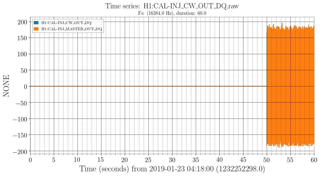
After discovering that CW injections died on January 18 at 22:31:22 UTC (14:31 PST), for unknown reasons, I have manually restarted the injections at 04:18:50 UTC on January 23 on h1hwinj1. The injections are visible again (see screenshot).
Keita, Dave:
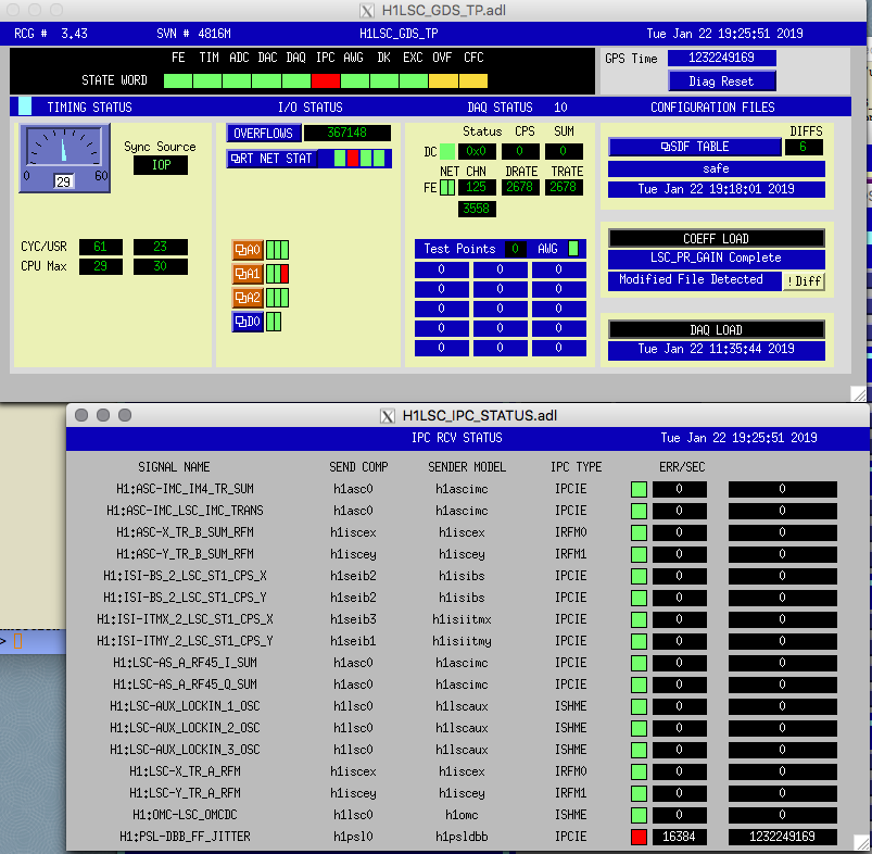
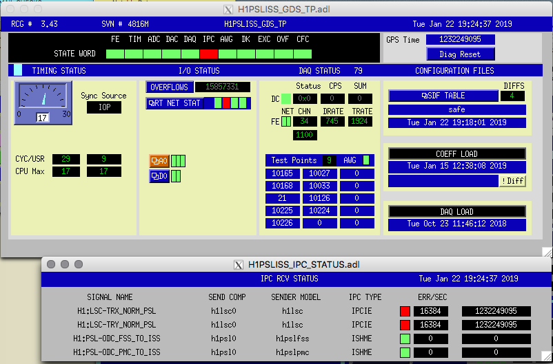
A reminder that the Dolphin cable was disconnected from h1psl0 in Oct 2018, back when the Dolphin network was not stable. The PSL-ISS model uses Dolphin IPC to receive the 3rd loop photo-diode signals from both ends, and the PSL-DBB model sends its jitter signal to the LSC. I had notched out these continuous Dolphin receive errors from CDS-Overview and the IPC-Overview, it is still visible on the GDS-TP screens. It is good practice after maintenance to check only the expected channels are in error (see attached).
WP8051 PEMCS, remove HAM6_SEPTUM ADC chan from generic list
Dave:
To fix the ADC-MEDM label for adc5_20 to show it is HAM6VAC_SEPTUM, h1pemcs was restarted. DAQ restart was required.
h1seiproc, latest model
Jim W
ODC removal
Keita, Jeff, Jenne:
ODC changes were made to: h1tcscs, h1lsc, h1omc, h1ascimc, h1asc, h1alsex, h1pemex, h1iscex, h1alsey, h1pemey, h1iscey. DAQ restart was required.
WP 8059 LSC Add POP_A_LF_IN1
Jenne:
new h1lsc model started, DAQ restart needed.
WP8054 Cal bug fixes
Jeff K
New h1calcs model was started, DAQ restart needed.
Slow Controls Beckhoff
Daniel, Dave:
PLC changes made to h1ecatc1plc[2,4]. New DAQ INI file generated. DAQ restart required.
DAQ GDS Broadcaster
Dave:
H1BROADCAST.ini was changed and loaded twice today. First change was to remove channels which had been removed from models beforehand. Second change was to remove the ODC channels which had been removed this morning, and add the timing FPGA and IRIGB channels back with their new names.
Restart Log:
Also see the following alog to find which frontend is yet to be installed for ODC descope.
https://alog.ligo-wa.caltech.edu/aLOG/index.php?callRep=46576
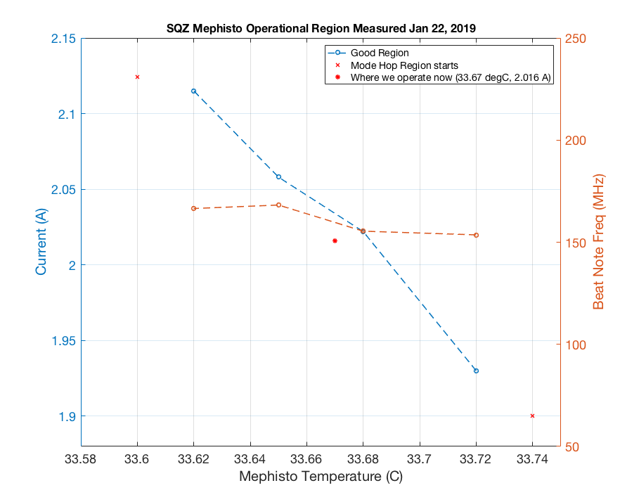
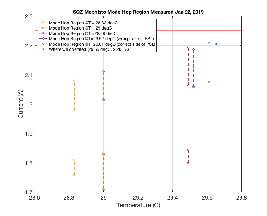
From alog46181 and alog46446 it almost seems like this Mephisto mode hop region was slowly creeping upon us since holiday (probably has been since the beginning since we ran away from 27.6 degC alog45519 which is now no longer a good region to operate). Today I finally found a setting where we can go from mode hop to mode hop and operate in the middle. We are how sitting ~0.1A away from mode hoping region. Using 2.4MHz/mA (I re-calibrated the current -> Hz with more data point) we now have +/- 240 MHz of wiggle room. Temperature doesn't appear to be affecting mode hoping as strongly as current does so I'm going to neglect that for now.

For a future reference, here's what I did:
I scanned the SHG to look at the multi mode peak (looking at transmission) and look at RF spectral analyzer to ensure that I had the beat note. I tried to go down in temperature but to compensate and keep the beat note at the same place I had to crank up the current, which I quickly ran into clamp current value (2.25A). Terry suggested I go up in temperature instead and hopefully the current wouldn't have to go so low to compensate while having a nice mode-hop free region to operate. I turned up the temperature by a degree, and sweep current left and right to see if there's any beat note. At 31.5 deg C region I was still limited by the clamp current and soon ran into another mode-hop region. I somehow skipped 32.5 deg C (or maybe I just couldn't find the beat note) and found the beat note at 33.6 deg C region (as plotted). I alternate between temperature and current to keep the beat note roughly at the same place (158 MHz +/-). I weren't patient enough to wait until the temperature really settle down before I write these frequencies down (so an uncertainty of +/- 1-2 MHz is possible).
Both of these QPDs acquired an NSUM channel. The medm screens reached from the IMC overview have been updated to also include the whitening.
The calibration is now according to alog 46482. The segments are in mW, whereas the new NSUM channels is in W incident to the mirror.
The IMC trigger had to be adjusted to account for the change in the MC2 TRANS SUM.
We also updated the ASC-AS_C QPD calibration. The previous calibration was 18dB too low, because the whitening gain was changed to 18dB from 36dB. We added the mW calibration into the segments and added a calibration relative to the incident mirror power (power towards HAM6) into the NSUM filter module.
Updated IM4 Trans NSUM calibration to be input power W: IM4 Trans NSUM Out = True Input Power [W] = IM4 Trans NSUM In [mW] * R_IM4/(T_IM4 * 0.1) * 1e-3 = IM4 Trans NSUM In [mW] * 4.157 [W/mW] T_IM4 (aka T_SM2) is 2400 ppm.
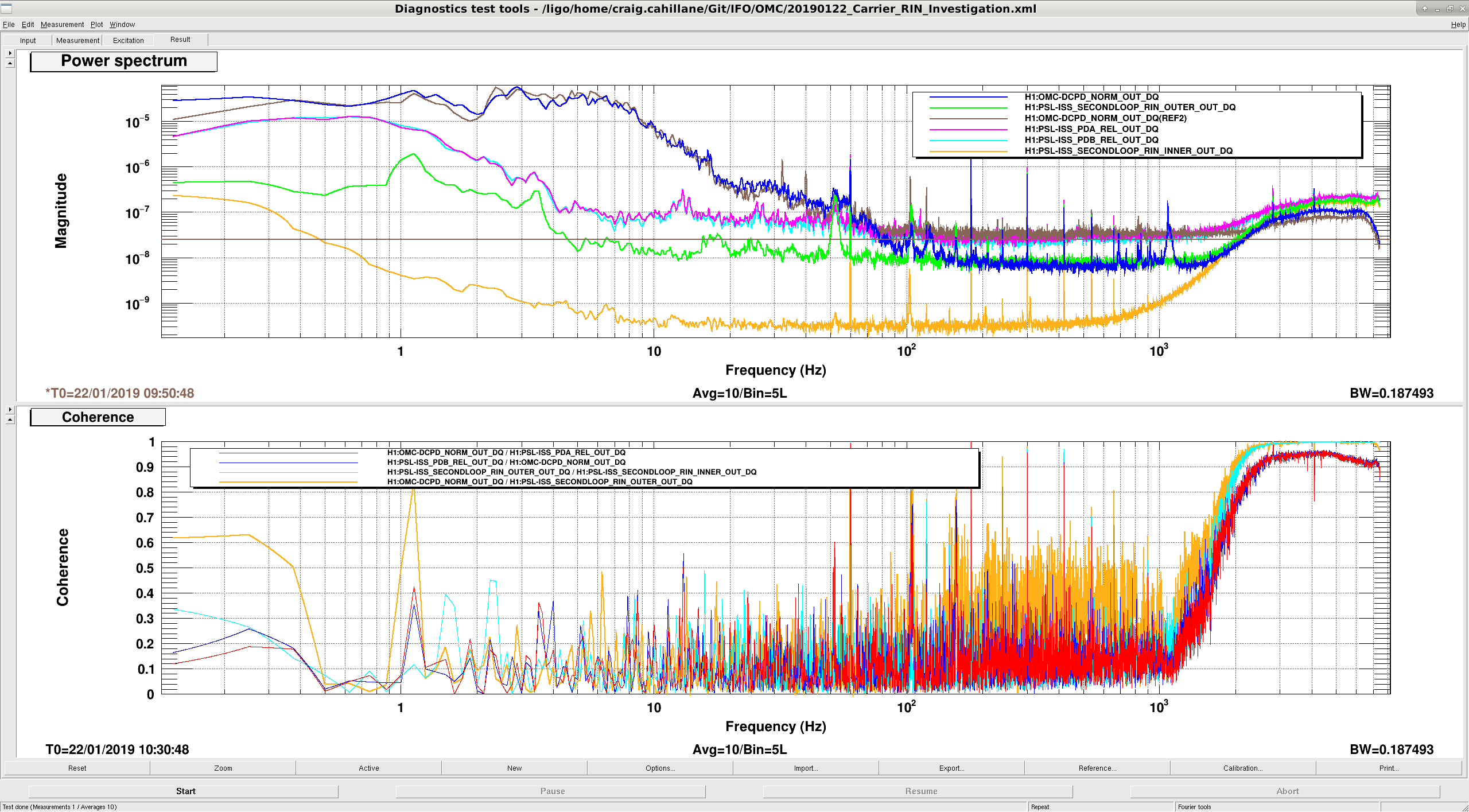
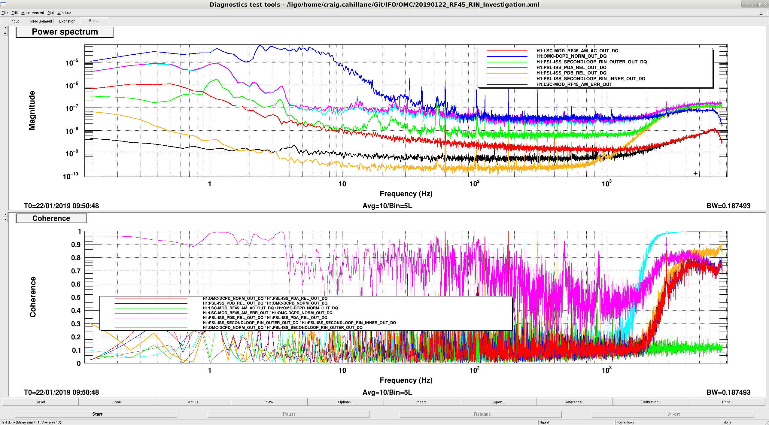
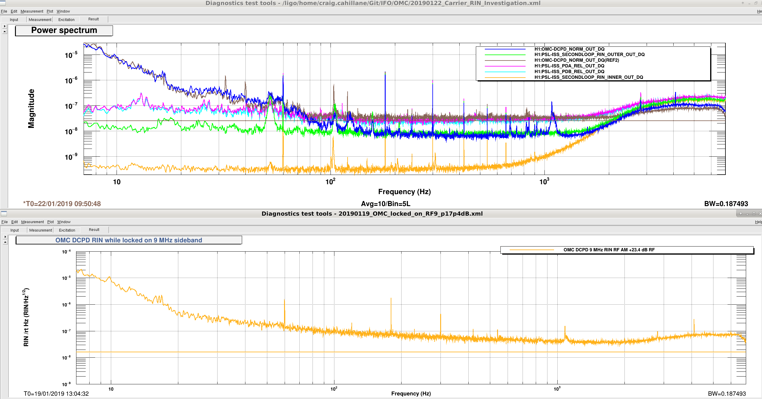
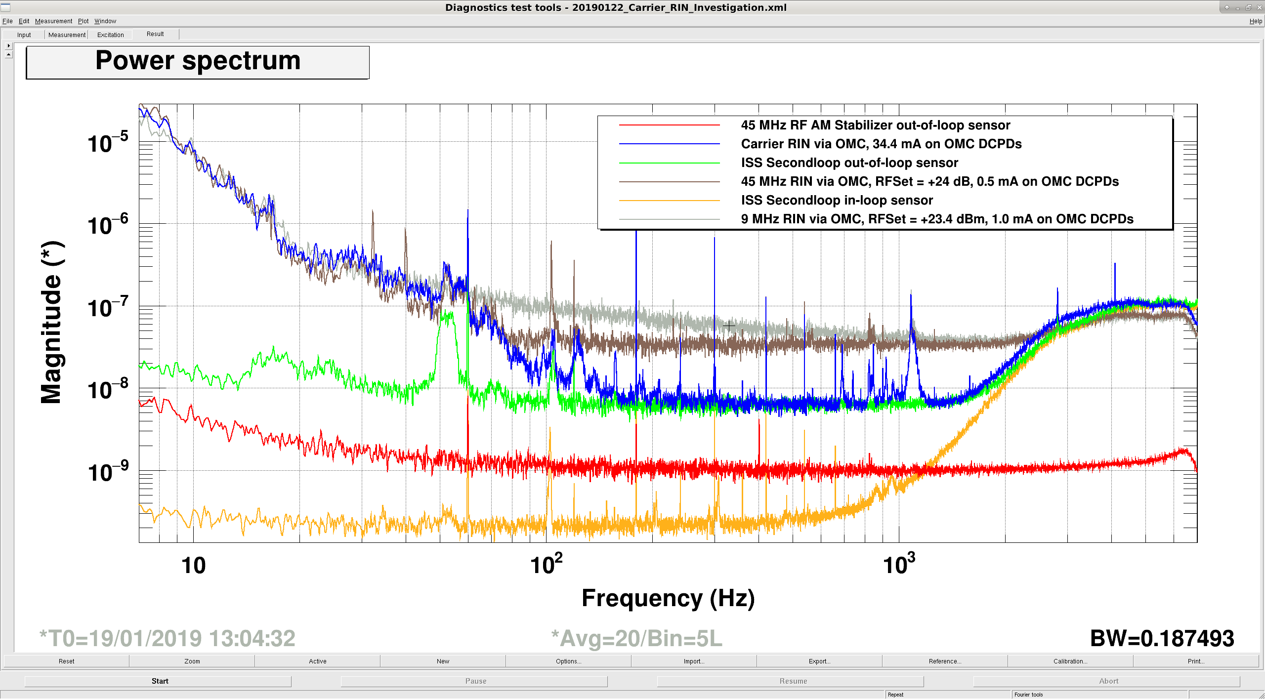
Koji, Craig Tonight we investigated intensity noise further. We locked the OMC on just the 45 MHz at 30 watts with 18 dB whitening gain, and then locked it on carrier at 20 W with 0 dB whitening gain. This is a repeat of here. We found that carrier and 45 MHz noise levels are similar. (See attachment one, carrier RIN is Blue, 45 MHz RIN is Brown) We were confused about why 100 and 1000 Hz the carrier noise is lower. We believe that this is mostly a shot noise effect. For 45 MHz we have 0.5 mA on the OMC DCPDs, while for carrier we had 34.3 mA. This corresponds to RIN shot noise levels of 2.5 × 10⁻⁸ 1/rtHz and 3.1 × 10⁻⁹ 1/rtHz. - The carrier is mostly limited by the ISS second loop sensing noise, as seen from the green curve in attachment one. - The 45 MHz flattens out right around our shot noise limit around 100 Hz. - Both carrier and 45 MHz have similar RIN spectra below 100 Hz. Recap: We know that the 9 MHz modulation depth has a real effect on the DARM noise, seen here as well. During the holiday party we were able to improve DARM noise by increasing the DARM offset, which could be due to increased carrier drowning out the 9 MHz noise. We also know that our OMC measured RIN in the sidebands cannot be explained from the noise in our RF AM stabilization scheme, or the ISS. We are pretty sure that the IMC FSR is reasonably close to our 1f modulation frequency. Conclusions: We here note that our shot noise from the OMC sideband measurements is not good enough from 80 Hz onwards to be able to tell what our actual 45 MHz sideband RIN noise level is. Below 100 Hz, carrier and 45 MHz RIN seem to be limited by the same mechanism, we don't know what it is. 9 MHz is not ever limited by shot noise in the OMC RIN measurement, and is overall worse than both carrier and 45 MHz RIN after 20 Hz, where it starts falling much more slowly. (Attachment three) ------------------------------------------------------------------------------------------------------------- Past OMC carrier RIN measurement
The AM stabilization circuit uses Schottky diodes to rectify the RF and get an error signal for its internal stabilization servo. At the highest output power, the flicker noise of these diodes will show as1/f noise in the power spectrum. This was not a problem with the old EOM, since it had higher Q and we never needed to go beyond 17 dBm drive power for 9 MHz, whereas we use ~24 dBm now.
PS. DTT has an import/export function.
Learned how to import in DTT. Shown is carrier, 9 MHz, and 45 MHz together.