New RIN filter modules have been added to the ASC-OMC_A and ASC-OMC_B QPDs. The calculation divides the SUM input by the SUM output. The SUM filter modules by default load a 1 Hz 2nd-order Butterworth low pass.
New filters:
New frontend channels:
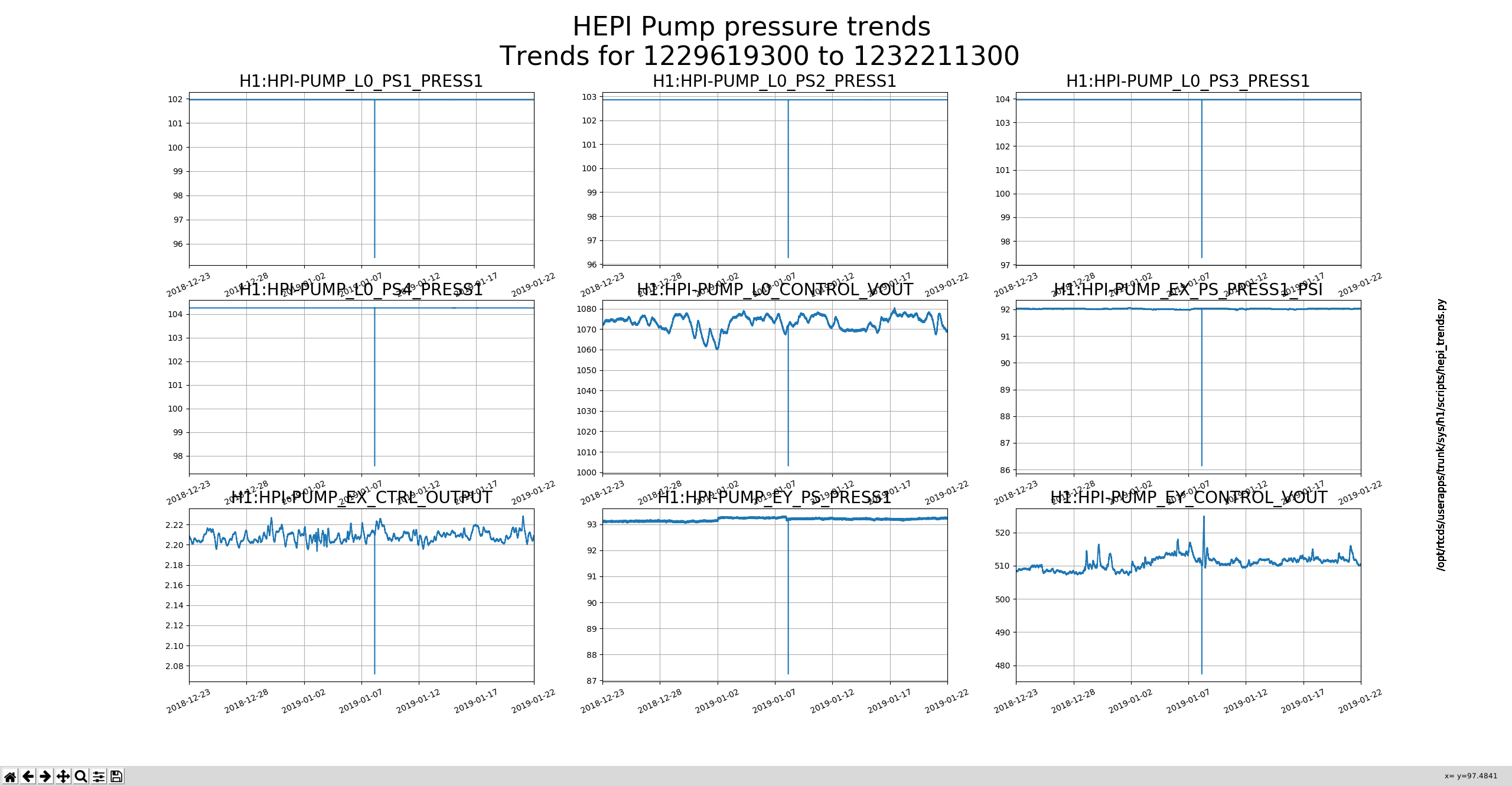
I forgot to attach a label indicating the date of pump replacement -> will do this at the next opportunity. Also, I had started the instrument air compressor for use with the pump cart's pneumatic isolation valve but didn't de-energize this until after 1400 hrs. local. The Y-end instrument air pressure will decay slowly and will remain "RED" until pressure falls below ??? threshold. Operators please ignore the "RED" MEDM field.
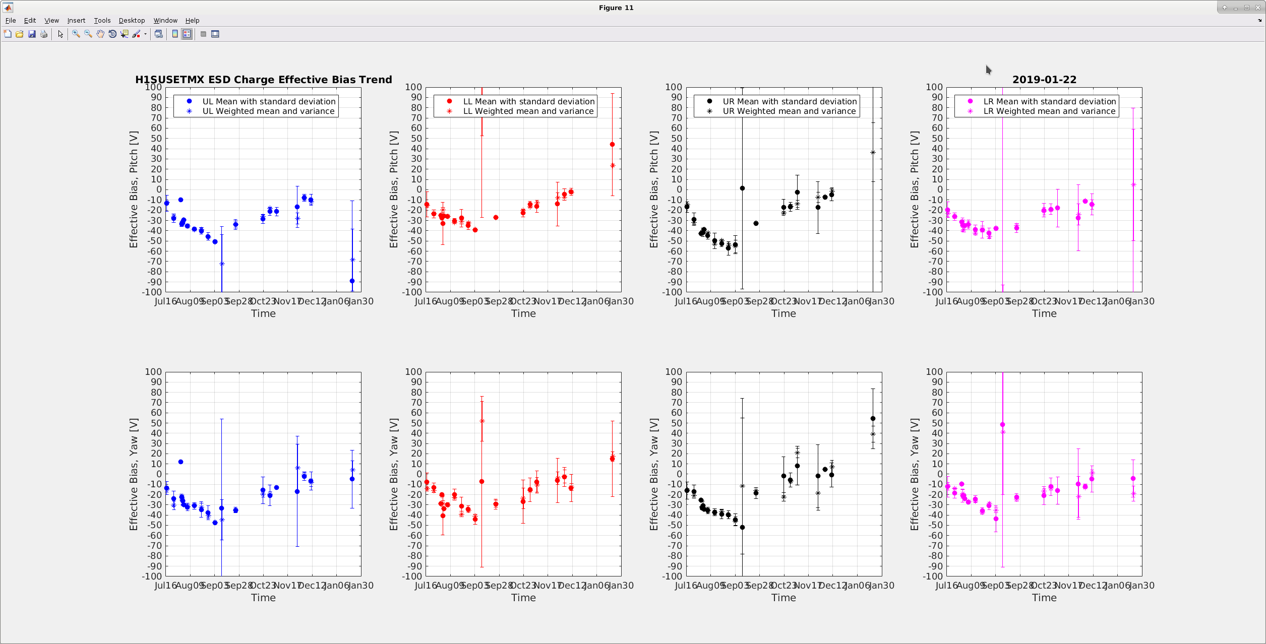
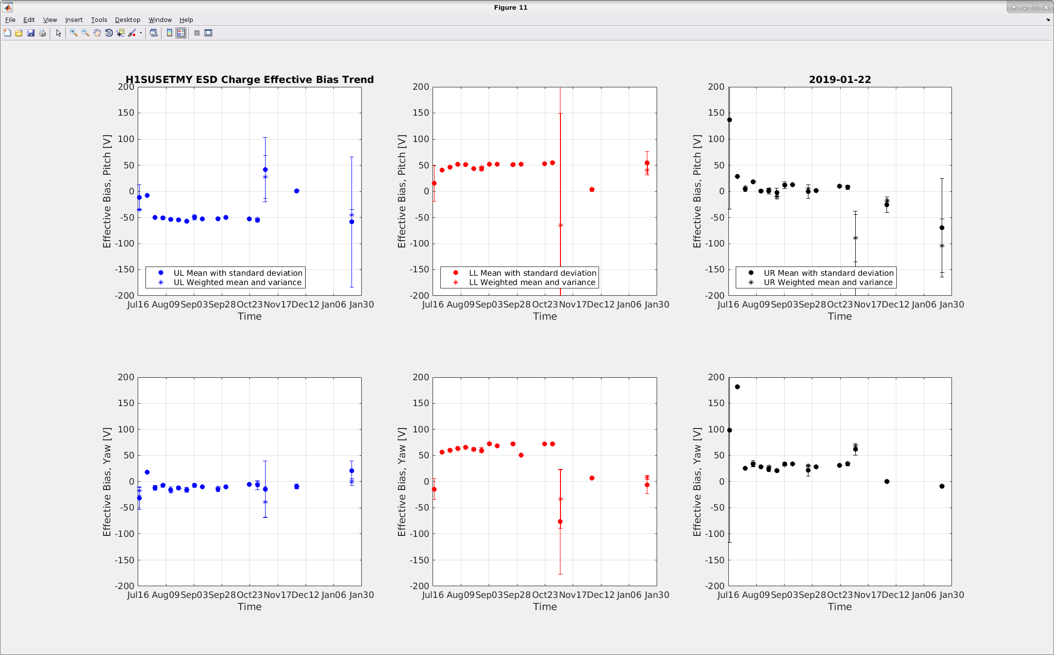
Patrick did the charge measurements today for the ETMX and ETMY. Later, Betsy and myself made the Matlab plots of the same (shown below). The data shows some excess noise for today's measurement. According to Patrick, he observed some noise in the OPLEV, hence we will do the measurements tomorrow once again. There were lots of activity at the end station today, hence this could also be one of the reason for excess noise.
TITLE: 01/22 Day Shift: 16:00-00:00 UTC (08:00-16:00 PST), all times posted in UTC
STATE of H1: Preventive Maintenance
INCOMING OPERATOR: None
SHIFT SUMMARY: Maintenance day
LOG:
15:15 Chris chewing tumbleweeds- X&Y
16:12 Kyle out to EY - GV18 work
16:32 Norco onsite - Dewar #77 (X-Mid)
16:33 Niko, Rick and Dimitri out to EX for PCal work
16:40 TVo and Daniel out to HAM5 to align the SRM heater/laser
16:51 Fil out to EX to install patch panel on VEA rack.
16:42 Vanessa to LVEA
16:56 Cheryl and Kara out to LVEA - HAM2
17:01 Peter out to Optics lab
17:10 TJ out to LVEA to join TVo and Daniel
17:14 Corey out to tend TCS chillers
17:23 Corey back
17:30 TCS team back
17:37 Karen out to EY
17:41 Travis out to EY to check status of work platform on BSC- PEM coupling
18:05 Travis back
18:11 PCal called - another 30 minutes should do it
18:14 Norco on site - Dewar #80 (EX)
18:25 Nutsinee out to ISCT6 - no IMC lock please
18:38 Peter back
18:50 PCal finished - EX is LASER safe
19:36 Dick out to CER for RF measurements
20:17 Chandra out to EY
20:18 Nutsinee back
20:20 Fil back
20:21 Kyle back from EY
21:12 Cheryl out to the LVEA
21:20 FIl out to LVEA
21:21 Peter out to Optics Lab
21:40 Cheryl need to re-align her camera on HAM2 while Patrick finishes the charge measurements
22:10 DAQ restart
22:25 IA started
22:26 Nutsinee out to ISCT6
23:21 it seems that approx 21:10 PRM sliders were moved to radically different positions. The cause is unknown.
23:48 Glitching in ALS slowing things down
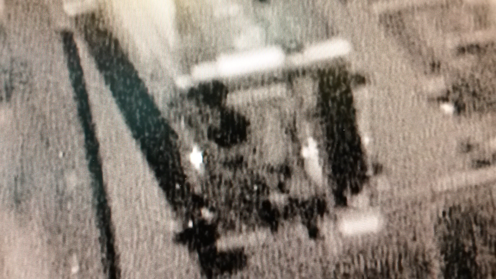
Installed the zoom lens, and got a good focus on the 2" REFL steering mirror, but once the enclosure was shut, the camera shifted, and once I revisited the camera/enclosure, the focus was not easy to re-find, so I looked at all available options, and ended up reinstalling the original lens, stopping down the aperture, and focusing on the IR light that's visible on the DKDP, which I'll use to evaluate the alignment of the output of the IO Faraday.
Upgraded imaged attached show the DKDP with the illuminator on, and the same optic with the illuminator off.
- Kara, Cheryl
A couple of smaller fixes:
Both of these QPDs acquired an NSUM channel. The medm screens reached from the IMC overview have been updated to also include the whitening.
The calibration is now according to alog 46482. The segments are in mW, whereas the new NSUM channels is in W incident to the mirror.
The IMC trigger had to be adjusted to account for the change in the MC2 TRANS SUM.
We also updated the ASC-AS_C QPD calibration. The previous calibration was 18dB too low, because the whitening gain was changed to 18dB from 36dB. We added the mW calibration into the segments and added a calibration relative to the incident mirror power (power towards HAM6) into the NSUM filter module.
Updated IM4 Trans NSUM calibration to be input power W: IM4 Trans NSUM Out = True Input Power [W] = IM4 Trans NSUM In [mW] * R_IM4/(T_IM4 * 0.1) * 1e-3 = IM4 Trans NSUM In [mW] * 4.157 [W/mW] T_IM4 (aka T_SM2) is 2400 ppm.
The new h1guardian1 machine has been running for a week now. Here are the latest statistics.
Network errors vs front-end restarts
Here is a trend of the ethernet errors (10 minute sample, baseline Rx Overruns=1048) referenced to this morning's front end and DAQ restarts
Tue Jan 22 11:29:34 PST 2019
RX errors 0 dropped 0 overruns 1048 frame 0
TX errors 0 dropped 0 overruns 0 carrier 0 collisions 0
Tue Jan 22 11:39:34 PST 2019
RX errors 0 dropped 0 overruns 3890 frame 0
TX errors 0 dropped 0 overruns 0 carrier 0 collisions 0
Tue Jan 22 11:49:34 PST 2019
RX errors 0 dropped 0 overruns 4461 frame 0
TX errors 0 dropped 0 overruns 0 carrier 0 collisions 0
Tue Jan 22 11:59:34 PST 2019
RX errors 0 dropped 0 overruns 4461 frame 0
TX errors 0 dropped 0 overruns 0 carrier 0 collisions 0
Tue Jan 22 12:09:34 PST 2019
RX errors 0 dropped 0 overruns 4461 frame 0
TX errors 0 dropped 0 overruns 0 carrier 0 collisions 0
Tue Jan 22 12:19:34 PST 2019
RX errors 0 dropped 0 overruns 4461 frame 0
TX errors 0 dropped 0 overruns 0 carrier 0 collisions 0
Restarts:
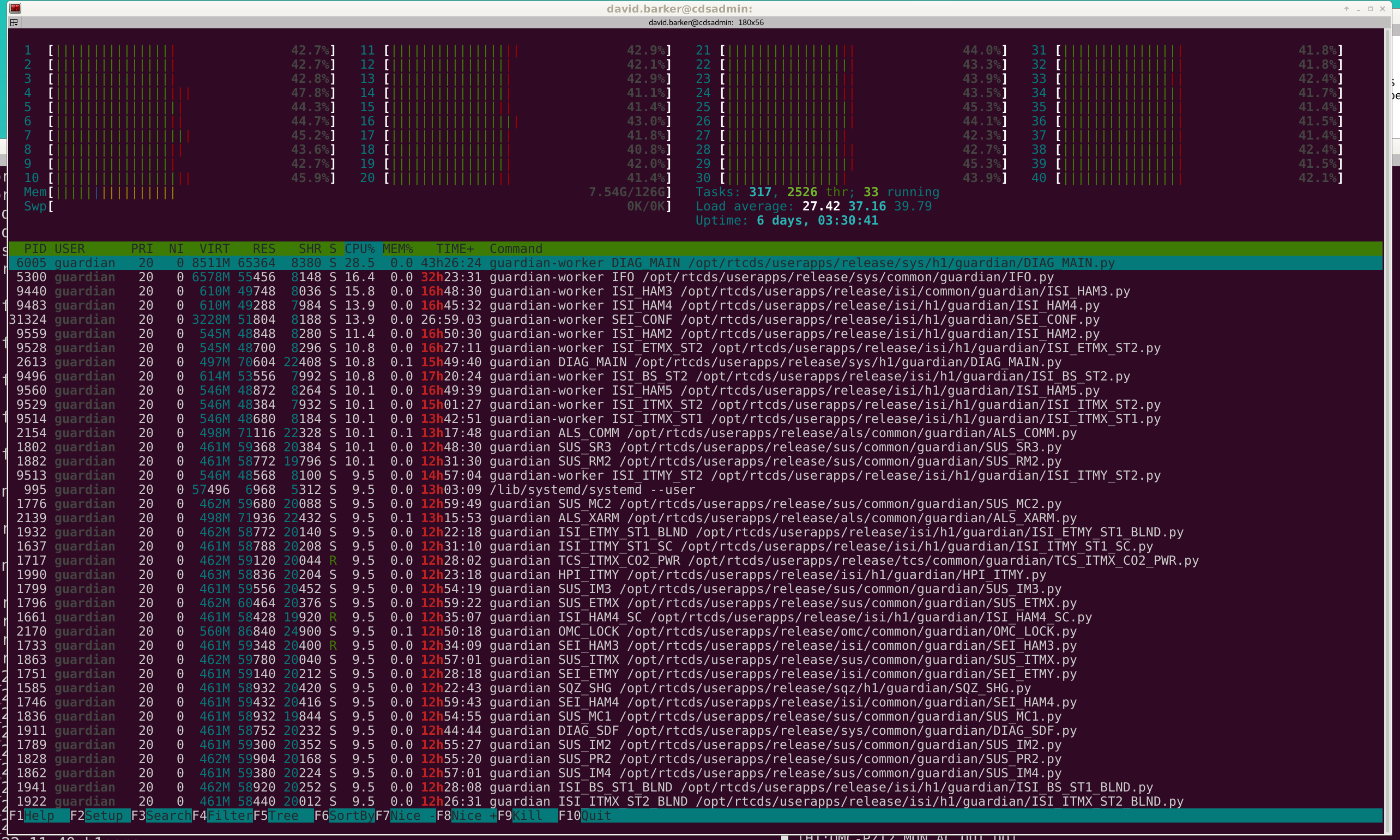
CPU/core usage:
See attachment for today's htop listing, compare with htop from last week
During this morning's DAQ restart the following channels were removed from the GDS_DMT broadcaster because they no longer exist:
Following today's changes there are further channels being 'sent' to GDS which no longer exist. Someone from the GDS/DMT group should verify that these channels are not used by GDS monitors, and perhaps look to see if any other channels should be removed from or added to the broadcaster.
I will removed these from H1BRAOADCAST0.ini and this change will go into effect on the next DAQ restart.
Timing diagnostic channels (duotone and IRIG_B) still do exist under different names.
https://alog.ligo-wa.caltech.edu/aLOG/index.php?callRep=46270
Laser Status:
Front End Power is 32.22W (should be around 30 W)
70W Output Power is 70.5W
Front End Watch is GREEN
70W Watch is GREEN
Laser Status:
Front End Power is 32.22W (should be around 30 W)
70W Output Power is 70.5W
Front End Watch is GREEN
70W Watch is GREEN
PMC:
It has been locked 5 days, 2 hr 55 minutes (should be days/weeks)
Reflected power = 10.53Watts
Transmitted power = 54.47Watts
PowerSum = 65.0Watts.
FSS:
It has been locked for 0 days 1 hr and 34 min (should be days/weeks)
TPD[V] = 3.202V (min 0.9V)
ISS:
The diffracted power is around 2.3%
Last saturation event was 0 days 3 hours and 57 minutes ago (should be days/weeks)
Possible Issues:
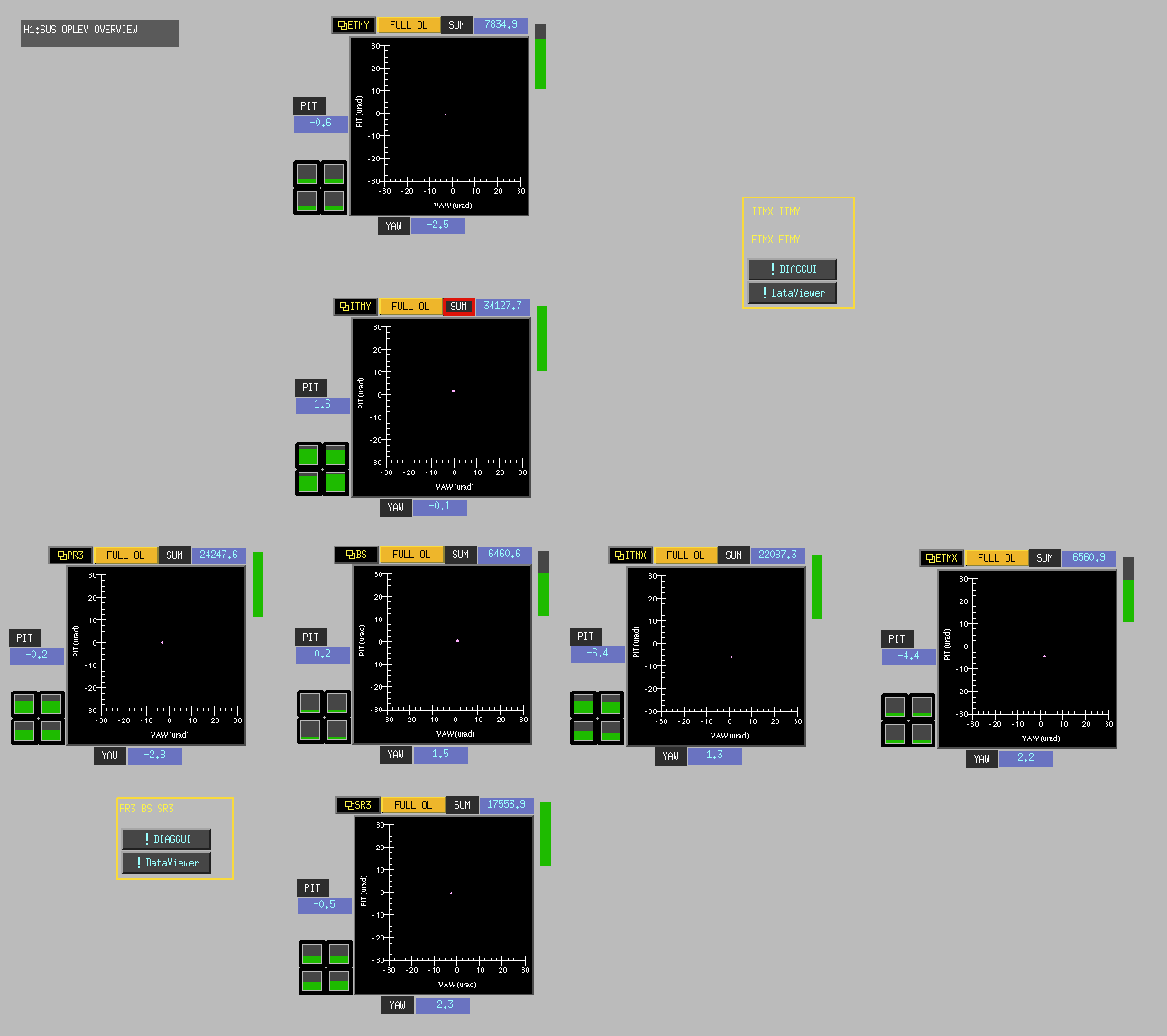
Centering on the OpLevs looks to be fine. The usual cast of characters still needing attention with no backups for relief. Images of Centering below as well as the ever noisy ITMX OpLev and slightly glitchy ETMY.
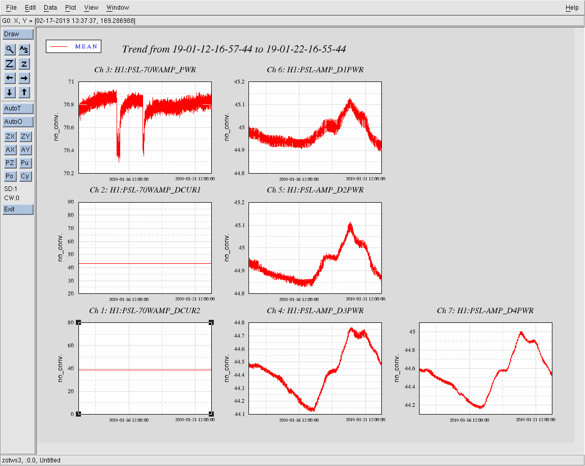
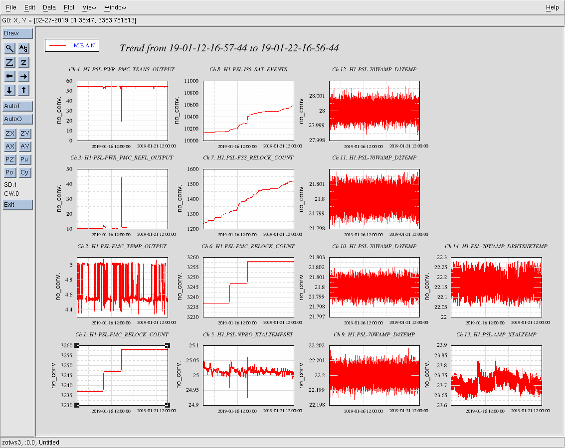
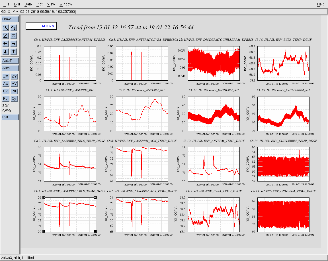
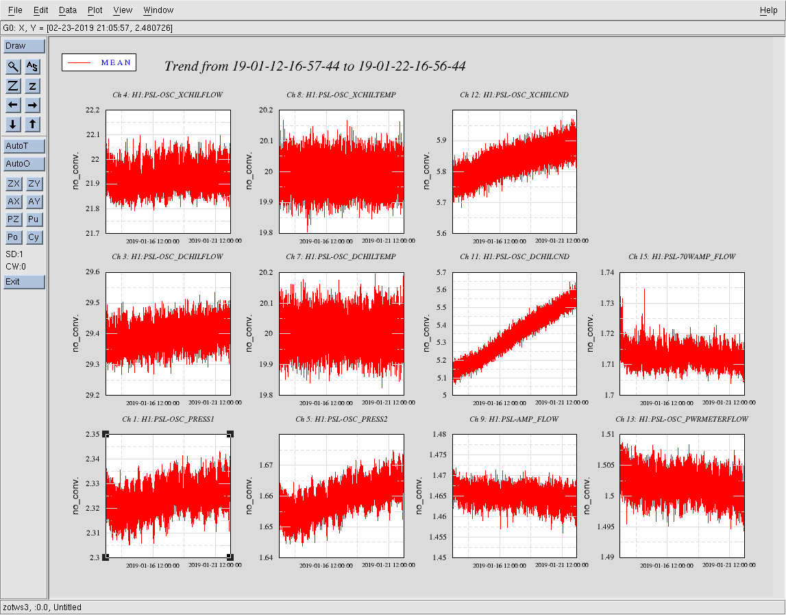
Everything looks normal with these trends. One note: the two downward dips in 70W amp power in WeeklyXtal.png (H1:PSL-70WAMP_PWR) are due to incursions into the PSL enclosure; this is indicated by corresponding changes in enclosure temperature, relative humidity, and laser room-to-anteroom differential pressure, found on WeeklyEnv.png. The first is during last Tuesday (1-15-19), when Cheryl and Robert were working on the IO system (optic swap and mount damping); the second was last Thursday (1-17-19), when Peter was performing FSS measurements.
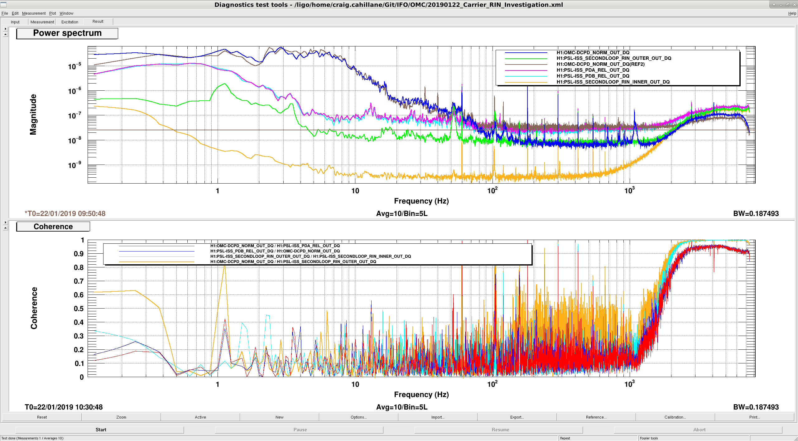
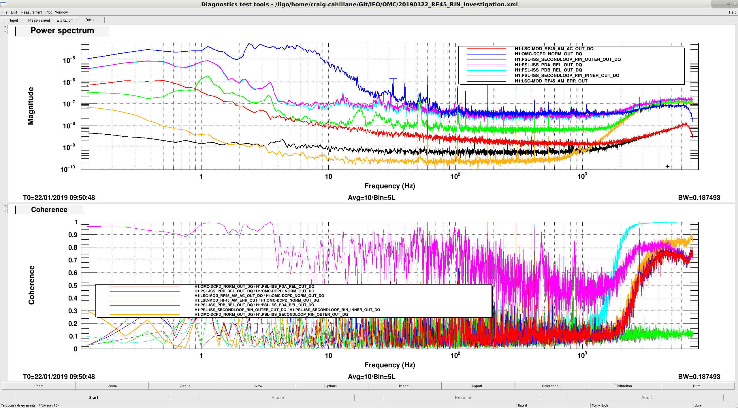
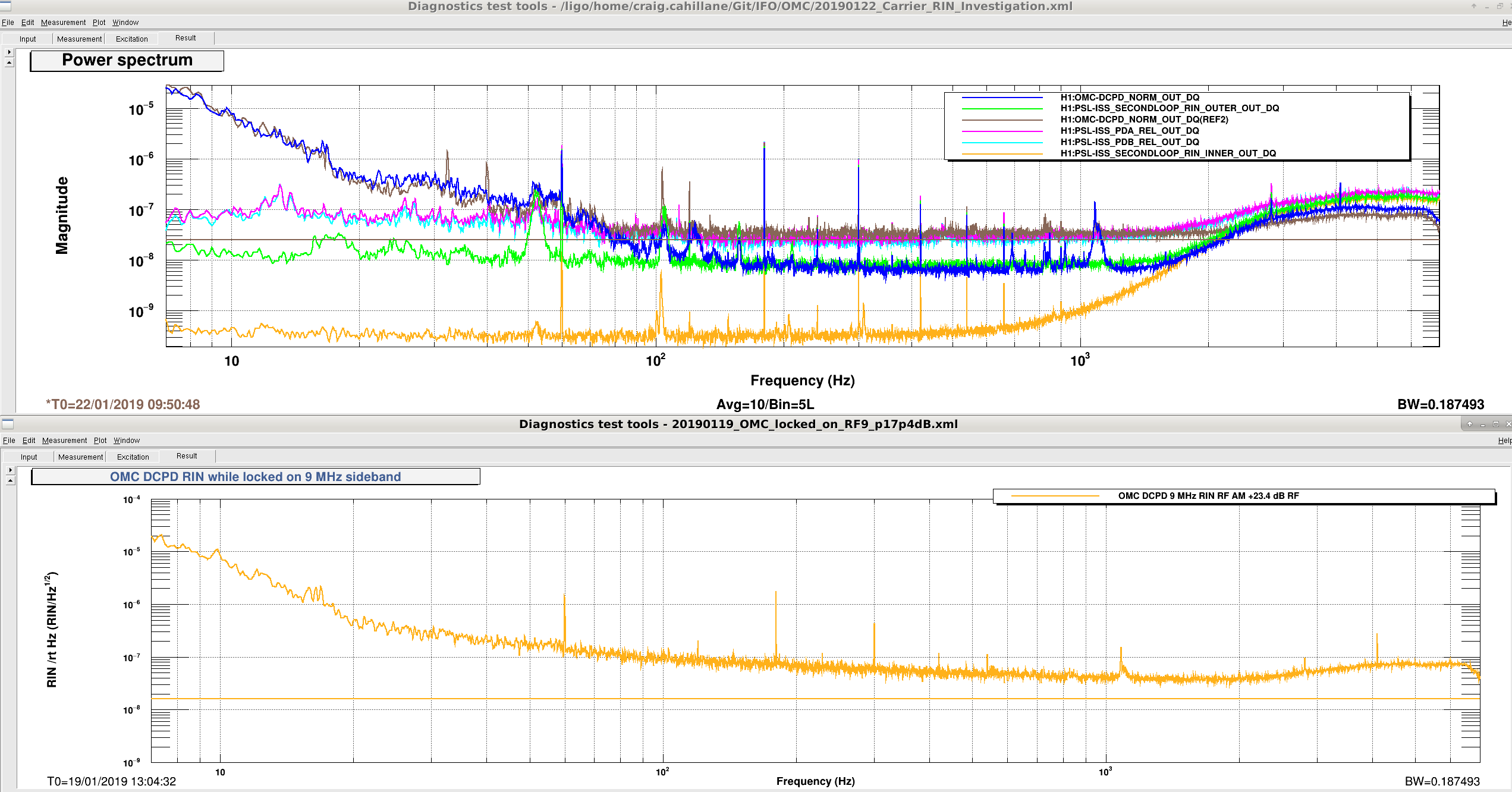
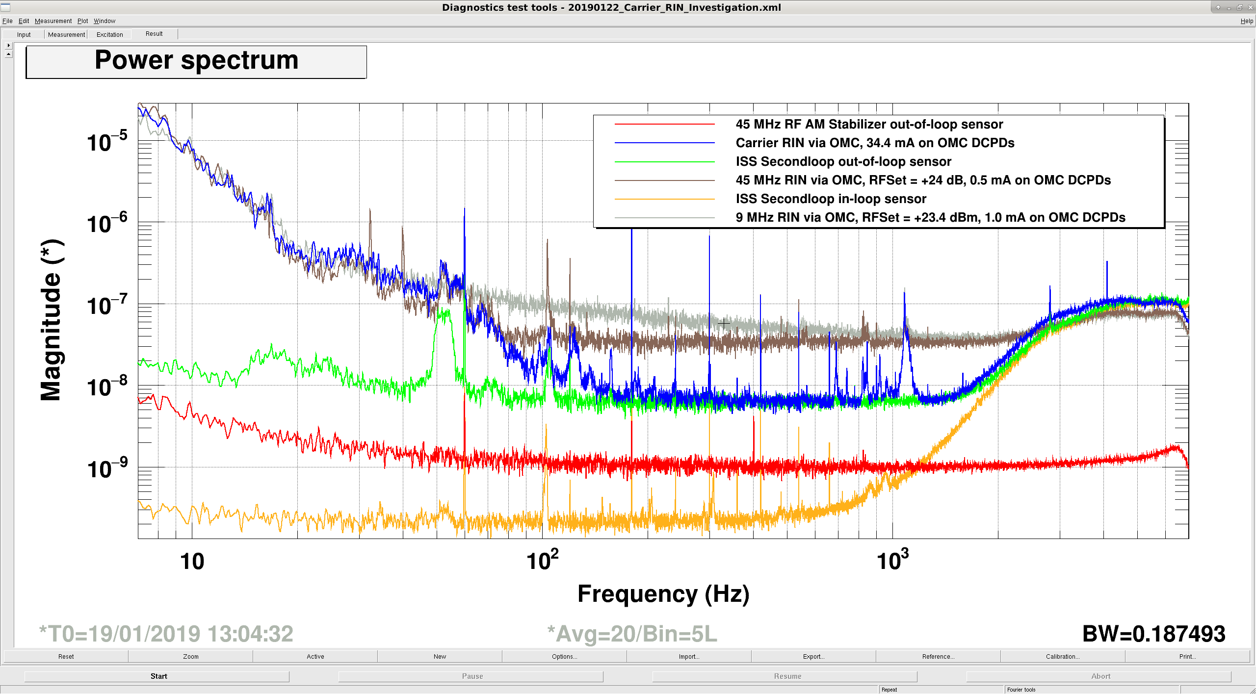
Koji, Craig Tonight we investigated intensity noise further. We locked the OMC on just the 45 MHz at 30 watts with 18 dB whitening gain, and then locked it on carrier at 20 W with 0 dB whitening gain. This is a repeat of here. We found that carrier and 45 MHz noise levels are similar. (See attachment one, carrier RIN is Blue, 45 MHz RIN is Brown) We were confused about why 100 and 1000 Hz the carrier noise is lower. We believe that this is mostly a shot noise effect. For 45 MHz we have 0.5 mA on the OMC DCPDs, while for carrier we had 34.3 mA. This corresponds to RIN shot noise levels of 2.5 × 10⁻⁸ 1/rtHz and 3.1 × 10⁻⁹ 1/rtHz. - The carrier is mostly limited by the ISS second loop sensing noise, as seen from the green curve in attachment one. - The 45 MHz flattens out right around our shot noise limit around 100 Hz. - Both carrier and 45 MHz have similar RIN spectra below 100 Hz. Recap: We know that the 9 MHz modulation depth has a real effect on the DARM noise, seen here as well. During the holiday party we were able to improve DARM noise by increasing the DARM offset, which could be due to increased carrier drowning out the 9 MHz noise. We also know that our OMC measured RIN in the sidebands cannot be explained from the noise in our RF AM stabilization scheme, or the ISS. We are pretty sure that the IMC FSR is reasonably close to our 1f modulation frequency. Conclusions: We here note that our shot noise from the OMC sideband measurements is not good enough from 80 Hz onwards to be able to tell what our actual 45 MHz sideband RIN noise level is. Below 100 Hz, carrier and 45 MHz RIN seem to be limited by the same mechanism, we don't know what it is. 9 MHz is not ever limited by shot noise in the OMC RIN measurement, and is overall worse than both carrier and 45 MHz RIN after 20 Hz, where it starts falling much more slowly. (Attachment three) ------------------------------------------------------------------------------------------------------------- Past OMC carrier RIN measurement
The AM stabilization circuit uses Schottky diodes to rectify the RF and get an error signal for its internal stabilization servo. At the highest output power, the flicker noise of these diodes will show as1/f noise in the power spectrum. This was not a problem with the old EOM, since it had higher Q and we never needed to go beyond 17 dBm drive power for 9 MHz, whereas we use ~24 dBm now.
PS. DTT has an import/export function.
Learned how to import in DTT. Shown is carrier, 9 MHz, and 45 MHz together.
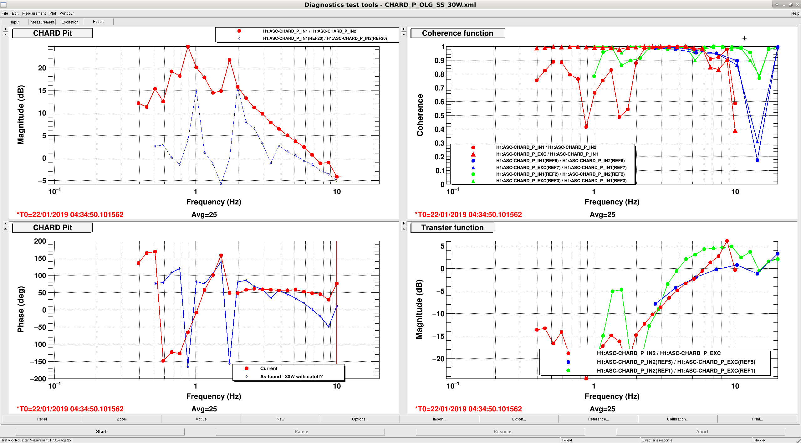
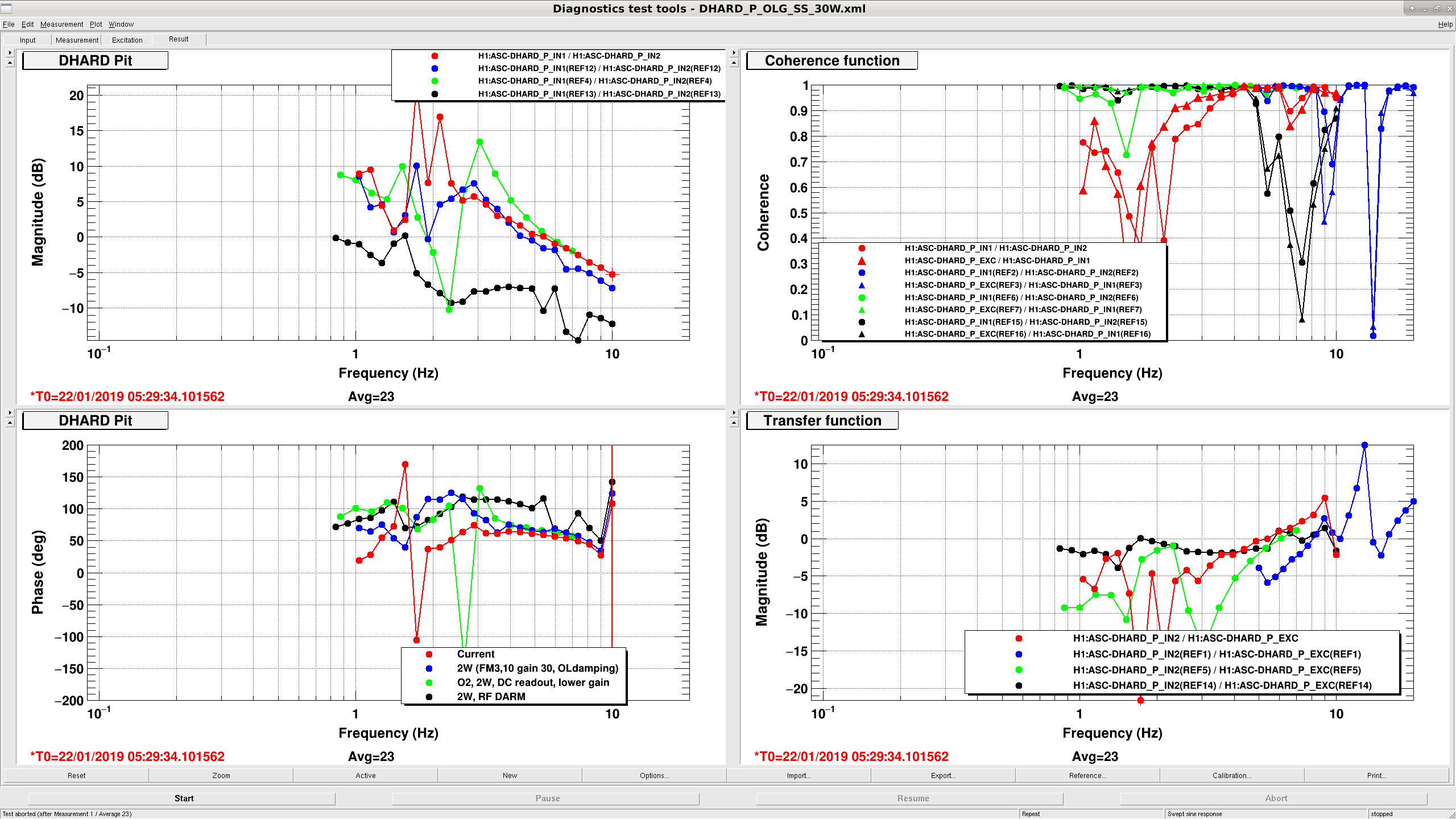
We took some CHARD, DHARD P measurements tonight, neither seem responsible for the 1 Hz oscillation reported earlier. We lost lock due to a 6.4 earthquake five hours ago.
These measurements were taken with a gain of 2 in CHARD P, and a SWSTAT of 38429, which means this happened before the gain is reduced to 0.6 (10dB lower) and the elliptic low pass at 10 Hz is engaged. Although we have 0 degrees of phase at 1 Hz, it seems like even after the changes in low noise ASC we should still have 10dB of gain at 1 Hz.
For DHARD P this was also taken before the changes in low noise ASC (gain is 50, SWSTAT is 38420), where the gain will be reduced by 4.5 dB and the one of the low passes will be engaged (either ELP10 or ELP17). The gain reduction for DHARD seems like the most suspect thing here, especially since the coherence is low for the 1 Hz point in Craig's measurement.
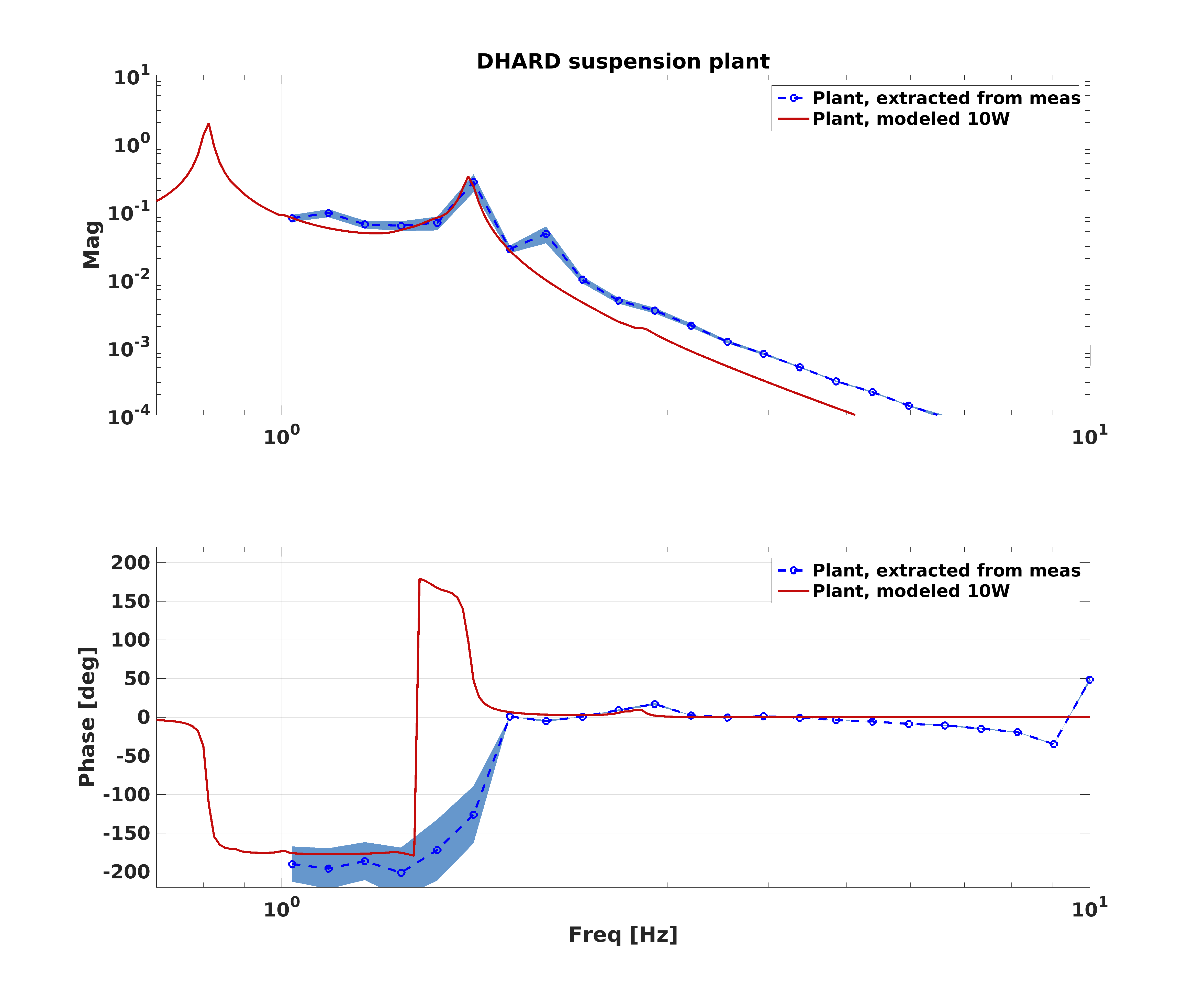
I think we may need to understand our DHARD plant better. I've taken the measurement from the parent alog, and extracted the suspension plant by dividing by the control filters that were in use at the time. I plot this against a model of the DHARD pitch plant at 10W. (Note that the measured data was taken at 30W, but the radiation pressure compensation was engaged to make it look like a 10W plant, which is why I compare to the 10W system.)
Also plotted are some rough uncertainties for the measured plant.
You can see that this measurement is consistent with Hang's in alog 46179, where he notes that the measured phase is doing opposite of what one expects for a pendulum system. So, while the OLG looks stable, we probably have something funky going on here.
Jenne Sheila
Summary:
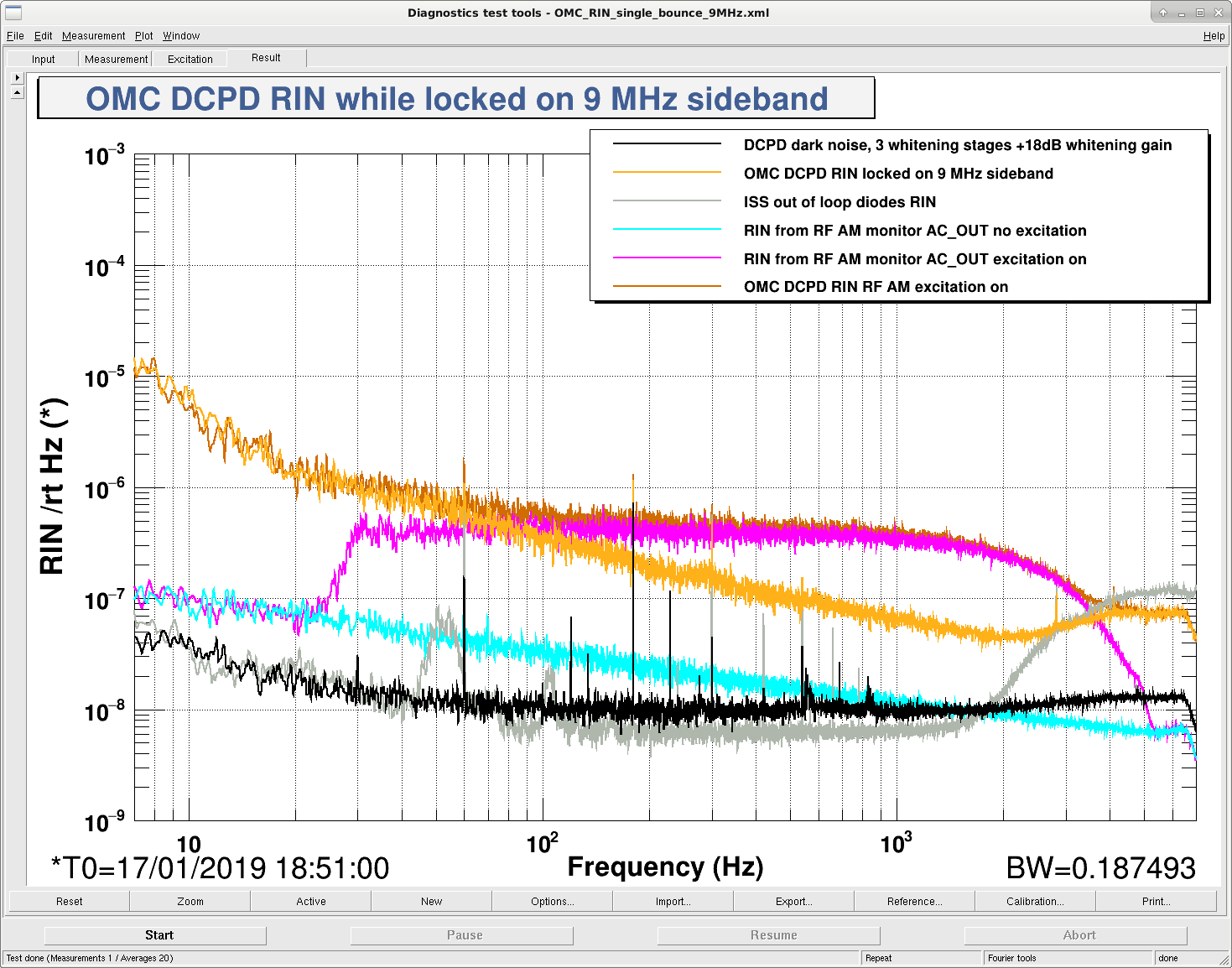
We measured the RIN on the 9 MHz sideband 00 mode through the OMC, and see that it is about a factor of 10 higher than the RIN predicted by the RF AM monitor.
Details:
The first time I tried this measurement, we were limited by the OMC DCPD dark noise 46197. These are the steps we followed this time:
The OMC DCPD signals (and dark noise) are calibrated into RIN here taking into account the extra 18dB of whitening gain. The EOM driver channel is normally calibrated into RIN assuming that the drive level is 17dBm according to Daniel, so this is divided by 3 because we are using 27dBm out of the EOM driver here.
The measurement with the excitation on shows good agreement between the RF AM monitor and the measured amplitude noise, so these calibrations are OK. We also have OK clearance above dark noise and the intensity noise seen by the ISS. So there is some additional source of intensity noise on the 9 MHz sidebands.
I was wondering what can add the RFAM more than we measure at the driver. Here are some speculations/thoughts
PeterF suggested (in an email) that the EOM matching circuit can pick up a stray radio field. If it is an ambient radio field, is the RF RIN gets better for a higher drive level (and worse for a lower level)? If the additional noise is proportional to the drive (i.e. the radiation is coming from the driver), the RIN is independent with the drive level. How can we add such a smooth broadband noise at the EOM...?
How about optical processes?
If the IMC PDH locking has the offset (e.g., due to static offset or rms offset by the AO path), this induces FM to AM conversion. Does the number make sense?
Is the modulation frequency matched with the IMC length? This can cause the modulation frequency noise to RFAM coupling.
---------
Note: The 9MHz drivers (see S1500125 or S1500126) cannot produce 27dB output. The 9MHz drivers saturate at about 24dBm setting. Of course, the injection is telling us the plot is true.
See equivalent L1 measurement in LLO alog 42928.
ODC removal (as per ECR 12045) has begun. Summary:
Detailed front end changes:
Further removal of ODC from the rest of the system (ISC, SUS, PEM, etc.) is deferred to later maintenance.
Following models were changed to remove ODC completely and compiled but not installed. Deferred to another opportunity.
h1ascimc (1 IPC sender (PCIE) and an entire ODC block were removed, doesn't use the library, one less fast channel on the frame)
h1pslpmc (1 sender (SHMEM) as well as an entire ODC block was removed from h1 model, ODC-related things were purged from the library, no change in fast channels)
p1psliss (2 receivers (SHMEM) for FSS and PMC as well as two ODC blocks were removed from h1 model, ODC-related things were purged from the library, one less fast channel on the frame)
h1pslfss (1 sender (SHMEM) as well as an ODC block were removed from h1 model, ODC-related things were purged from the library, no change in fast channels)
h1tcscs (1 sender (SHMEM) as well as an ODC block were removed from h1 model, ODC-related things were purged from the library, one less fast channel on the frame)
h1iscex (done by Jamie, no change in fast channels)
h1alsex (1 sender (SHMEM) as well as an ODC block were removed from h1 model, doesn't use library, one less fast channel on the frame)
h1alsey (1 sender (SHMEM) as well as an ODC block were removed from h1 model, doesn't use library, one less fast channel on the frame)
h1lsc (1 sender (PCIE) and an ODC block are removed from the h1 model, doesn't use library, one less fast channel on the frame)
h1omc (1 sender (PCIE) as well as an ODC block were removed from h1 model, ODC-related things were purged from the library, one less fast channel on the frame)
h1pemex (1 sender (SHMEM) as well as an ODC block were removed from h1 model, doesn't use library, no change in fast channels)
h1pemey (1 sender (SHMEM) as well as an ODC block were removed from h1 model, doesn't use library, no change in fast channels)
all SEI models at the end stations (done by JeffK)
Following models are yet to be changed.
all sus models (TBD by JeffK)
Update on Jan 22
During the maintenance on Jan22, the following models without ODC were installed.
h1lsc, h1ascimc, h1omc, h1iscex, h1alsex, h1alsey, h1tcscs, h1pemex, h1pemey.
(h1asc was updated and installed for something unrelated to ODC.)
Remaining frontends that are yet to be replaced with new ones without ODC:
All SUS (models are yet to be changed/compiled).
All end station SEI (models are ready).
h1pslpmc, h1pslfss, h1psliss (models are ready).
Remaining frontends that will be changed again after new HW injection infrastructure is confirmed to work by transient injection group(s):
h1calex (model is yet to be done, PINJX will be completely removed).
h1odcmaster itself (this will be retired).
Update Feb/04/2019
All SUS models were modified to remove ODC, compiled successfully, but not installed. These are:
h1susetmx, h1susetmy, h1susitmx, h1susitmy, h1susbs, h1suspr3, h1suspr2, h1susprm, h1sussr3, h1sussr2, h1sussrm, h1susmc1, h1susmc2, h1susmc3, h1susomc, h1susopo, h1susim (and h1sustmsx and tmsy and h1sushtts on Feb/05/2019)
One PCIE IPC sender and one fast channel were removed per each model, as well as many EPICS channels. One new EPICS channel (ODCCHAN_PLACEHOLDER) was added per each model.
Library parts (QUAD_MASTER, QUAD_ITM_MASTER, BSFM_MASTER, HSTS_MASTER, HLTS_MASTER, OMCS_MASTER, OPOS_MASTER) are still compatible with old models, so if you want to compile any of old sus models with the new library you can. In that case ODC IPC will be plugged to zero.
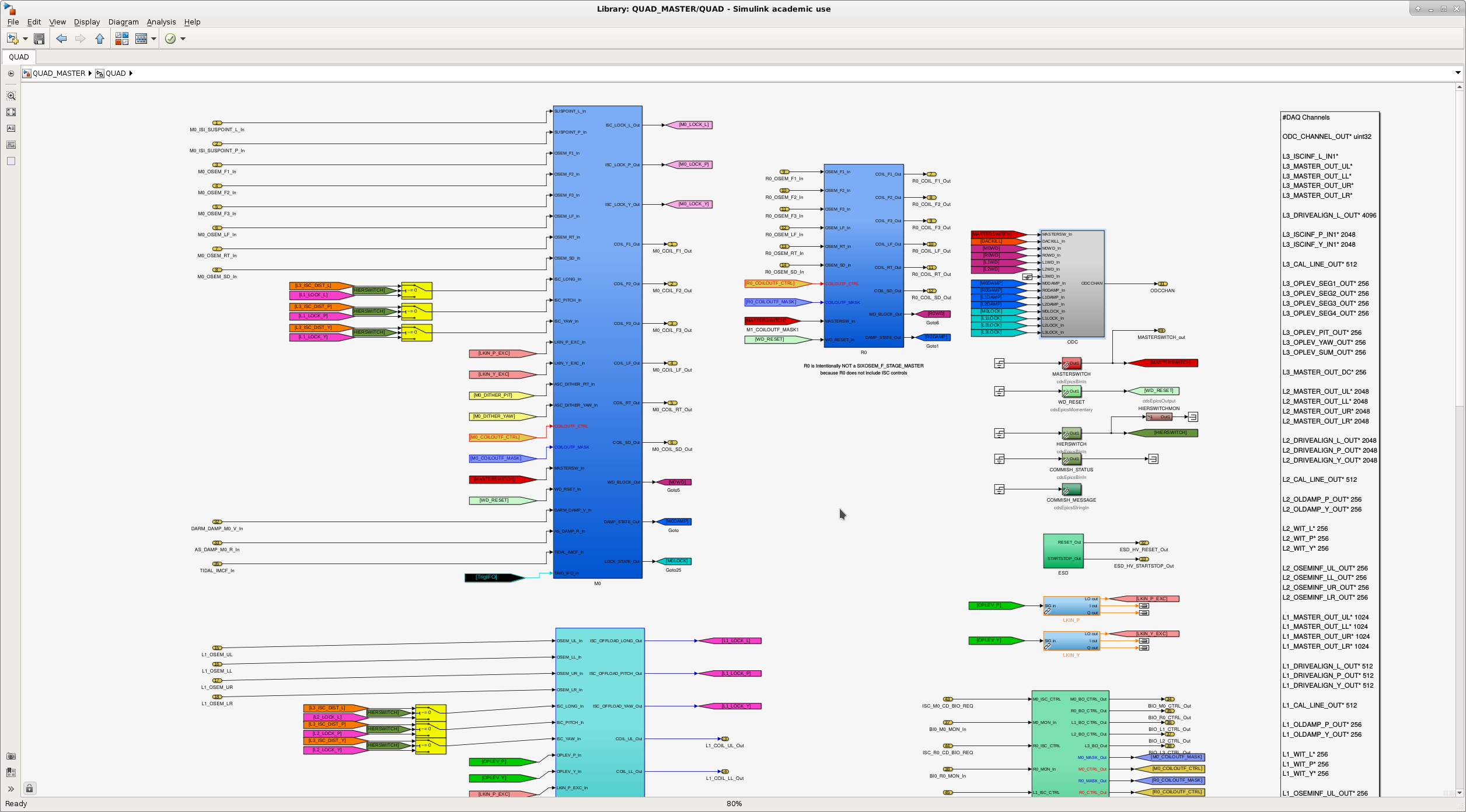
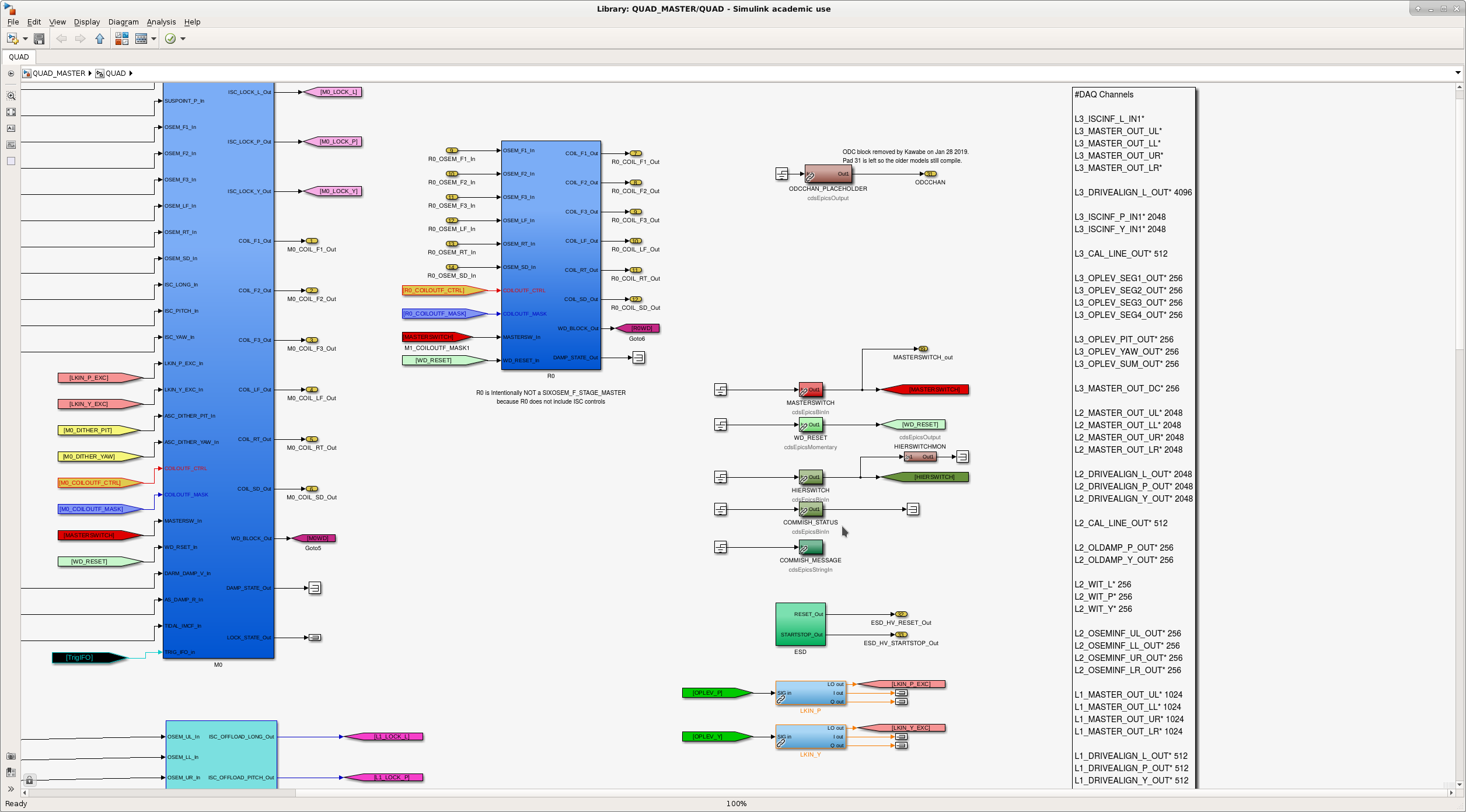
Attached are typical before/after view of the library parts.
Boo. I just assumed that MC1, MC2 and MC3 all use HSTS_MASTER library part, but MC2 actually uses MC_MASTER part. I only edited HSTS_MASTER and individual model (h1susmc1, 2, 3).
As a result, ODC was not completely removed out of h1susmc2. This is going to be fixed in the next opportunity.
Keita and Rahul Keita showed me how to make changes to the front end model of SUS. We made changes to MC_MASTER library parts to remove ODC. We complied h1susmc2 successfully, however we didn't install it.
Back in Sept, the locations of the anemometers up by the EndX wind fence were shown on a sketch. Today ChrisS help move the Wind_Speed_3 sensor from 12' up to 2' AGL; the horizontal location is within a foot, coord +3,-9. That height above ground level puts the sensor in the middle of the gap between the bottom of the wind cloth and the ground. We want to study the wind profile as we move from in the middle behind the cloth to in the gap below the cloth. We expect it to be higher than behind the cloth but is the velocity actually higher than the free stream wind (Wind_Speed_1)-is it accelerated? So, we'll see. Report later after we have some wind in the ~right direction.
Results reported by Hugh in LHO aLOG 46259