NikoL, Dimitri Estevez (Virgo), SudarshanK (remotely), RickS
This morning, we calibrated the Yend Pcal readback channels using the working standard (WSH) that we had delivered to Yend yesterday afternoon and left powered up overnight.
We encountered a couple of software issues related to the updates to calculate the force coefficients in the frontend, but we were able to complete the measurements.
The power sensor coefficients calculated today were very close to the values we calculated from the measurements made on December 13.
| Sensor | Dec. 13 | Jan. 15 | ratio (new/old) |
|---|---|---|---|
| Tx (V/V) | -0.480810 | -0.480448 | 0.99925 |
| Rx (V/V) | -0.715832 | -0.715410 | 0.99941 |
We decided to go ahead and switch to using the force coefficients calculated in the frontend (using JeffK's new code). We updated the epics values using the data from our Dec. 13th measurement and captured in the .txt file attached in that entry. We "put" the values into the epics records by just copying and pasting the text in the lho_yend_pcal_epics_created-20190115.txt file attached to this entry and in the SVN at
/ligo/svncommon/CalSVN/aligocalibration/trunk/Runs/O3/H1/Results/CALCS_FE/yend_pcal_epics_created-20190115.txt
The new Pcal power sensor calibration values (N/V) and comparisons with the previous values are:
| Force coeff. | New | Prev. | ratio (new/old) |
|---|---|---|---|
| Tx (N/V) | 1.5049e-9 | 1.5160e-9 | 0.9927 |
| Rx (N/V) | 1.0223e-9 | 1.0475e-9 | 0.9759 |
We checked the beam spot locations on the Rx power sensor aperture. The beams are reasonably well centered; both beams are incident on the integrating sphere in the attached photo.
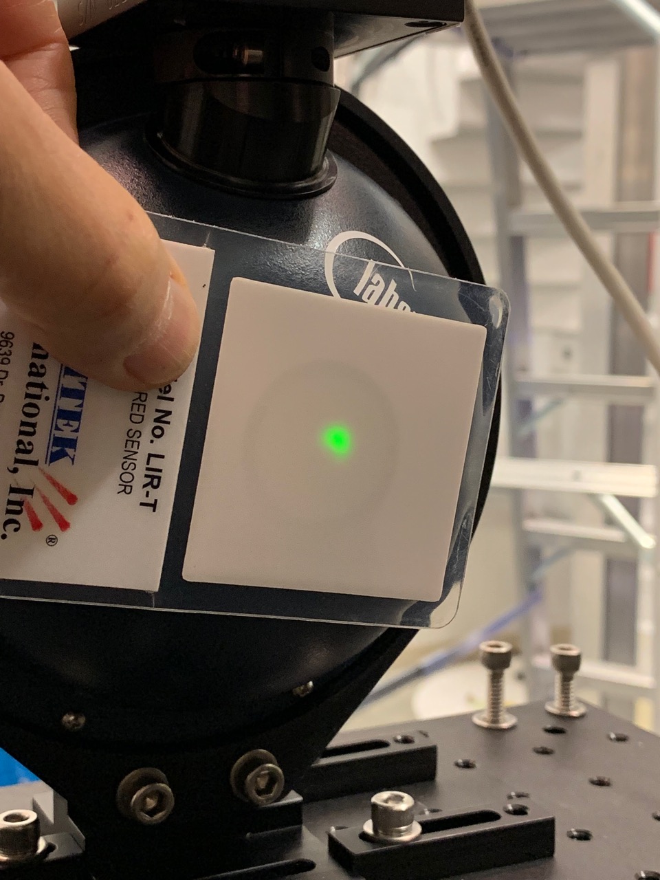
Notes from today's Pcal calibration work attached below.
One of the end station calibration procedures involves using the Martel voltage supplier at both the end station and the LSB lab to calibrate voltage measurements. The output from the LSB lab measurements is:
|
WSH |
Input (from Martel) [V] |
Output (from Keithley) [V] |
|
-4 |
-4.0001 |
|
|
-2 |
-2.0001 |
|
|
-1 |
-1.0001 |
|
|
0 |
0.000008 |
|
|
1 |
1.00001 |
|
|
2 |
2.0001 |
|
|
4 |
4.0001 |
The attached text file to the main entry, called out stored in the CalSVN repo as /ligo/svncommon/CalSVN/aligocalibration/trunk/Runs/O3/H1/Results/CALCS_FE/lho_yend_pcal_epics_created-20190115.txt *had* had a bug in it -- see LHO aLOG 46472. After finding the bug, the contents of the file were replaced in the above attachment, and it was run and installed in the front-end. For posterity, I've saved the file as a new name in the Cal repo: /ligo/svncommon/CalSVN/aligocalibration/trunk/Runs/O3/H1/Results/CALCS_FE/lho_yend_pcal_epics_created-20190116.txt
We are using In-air POP_X WFS so I shook ISCT1 to check for coupling. The figure shows that none was found.
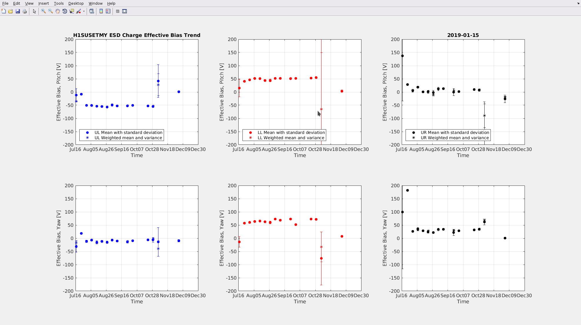
I noticed that the long trend data of ETMY charge has not been plotted and posted since October. Both ETMs have had charge data collected in Dec, but ETMY data has been throwing errors in the Long_Trend.m matlab plotting script. Since Georgia was the last to have successfully plotted the data, I solicited her for a hint. She reports that in October, she had to create a separate script which had the LR data removed in order to get it to run successfully.
So, for the future, in order to plot the longer trend data of charge use the following scripts in /ligo/svncommon/SusSVN/sus/trunk/QUAD/Common/Scripts:
for ETMX use the normal Long_Trend.m
for ETMY use Long_Trend_ETMY_LHO.m
(I've updated the wiki page for this https://awiki.ligo-wa.caltech.edu/wiki/ESD_OPLEV_Charge)
Attached is the plot with the new data set measured in Dec. Note, charge on ETMY was up near ~50V before we vented Nov 13, 2018 in an to attempt to fix the LR ESD connection. The attempt was unsuccessful, however we managed to blow off some of the accumulated charge before closing again. So, there is that.
Daniel, Nutsinee
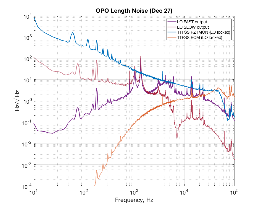
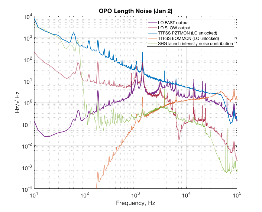
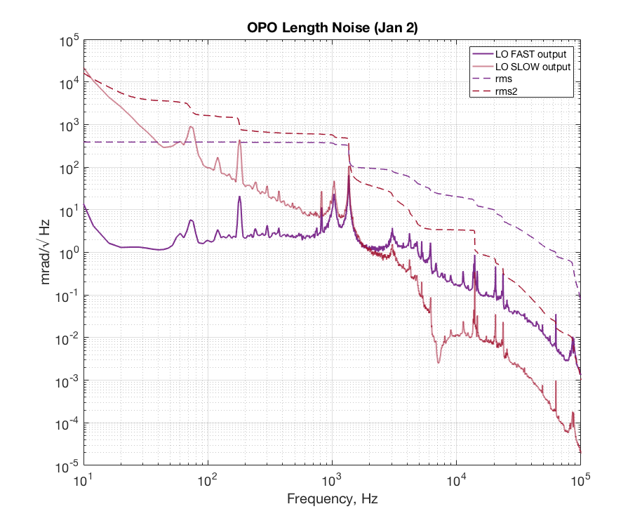
Attached two plots of LO and TTFSS control signal. One shows TTFSS control signal when LO was locked (Dec 27) and the other shows TTFSS control signal when LO was unlocked (Jan 2). Everything is calibrated in green Hz/V (say free-running laser would be ~200Hz/sqrt(Hz) at a 100Hz).


Our scheme makes the laser follows the OPO, thus the TTFSS control signal should see mostly free-running laser noise. And whatever's left is taken care of by LO. Thus we look at LO spectrum for OPO length noise. LO fast signal is fed to additive offset of the TTFSS and slow signal goes to OPO PZT.

The feature at and around 1.4kHz is what we thought might be the actual length noise of the OPO as the line disappear from TTFSS control signal when you turn on the LO loop. But there are lines between 10lHz-30kHz that only shows up on the TTFSS control signal when the LO is locked. Suggested that they are introduced by the LO loop (possibly OPO PZT). Could be notched out. For the rest of the noise, I'm not sure if we know where they came from. Part of it could be PSL LO fiber noise. It'd be nice to compare to a spectrum taken with the OMC.
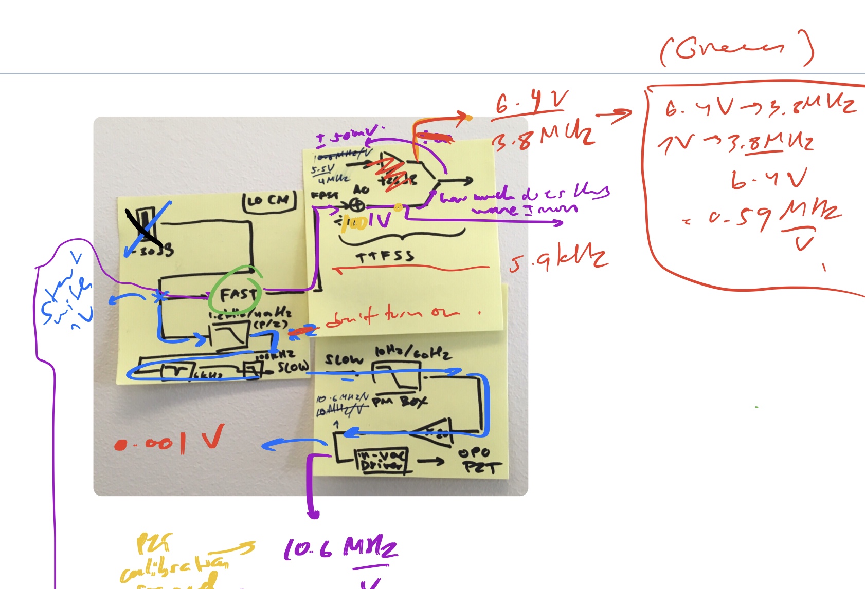
To get the laser PZT calibration I moved OPO PZT by 0.5 V (corresponds to ~10MHz), looked at TTFSS PZTMON (not /25) and 158MHz beat note. The PZTMON read out is then multiplied by the filters on the interface board to get the actual voltage sent to the laser PZT. The result is 1.7MHz/V (in red).
For LO fast output calibration V/Hz I relied on TTFSS IMON Vpp/FWHM. There's a factor of 100 at the additive offset.
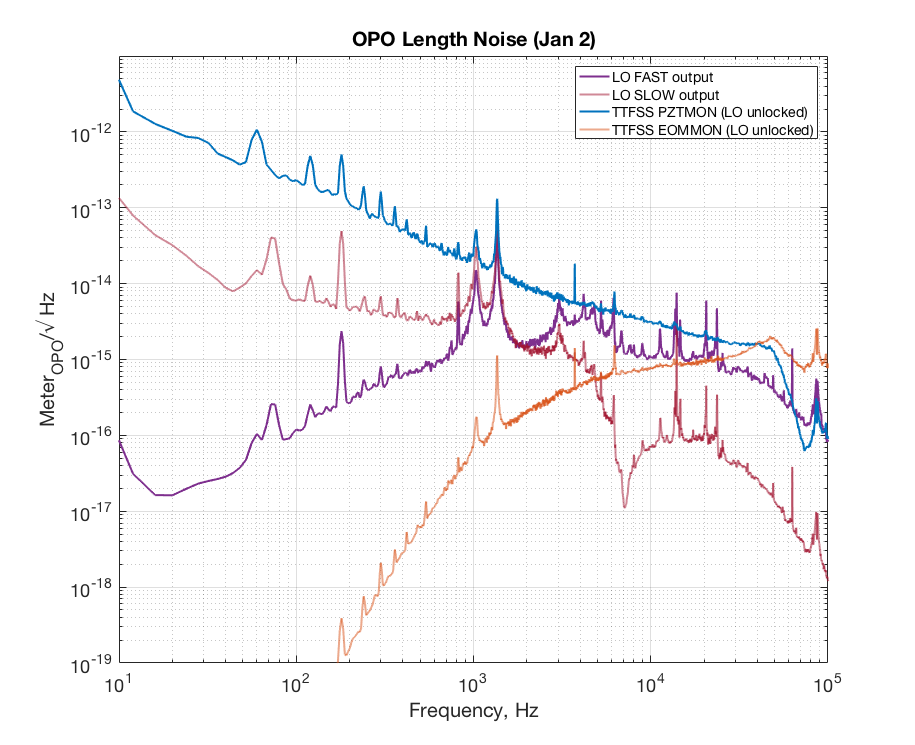
Files in m/sqrt(Hz) and rad/sart(Hz) attached below.
Note that h1inj1 and h1inj2 at LHO have now been patched, rebooted, and brought up to SL7.6
Ana, Madox, Yasmeen, Stefan
We went to EX and EY to remove the CNS II Timing Diagnostic System GPS clocks and measure the GPS antenna cable lengths as part of work permit 8044. This will have NO IMPACT on anything outside of timing diagnostics.
We suspect that the cable connects to a cable in VEA after 90 ft which goes up to the roof. The total measured length at both end stations was about 210 ft;, however, this might be wrong if the cable to the roof has a different velocity factor than the LMR-195 going from VEA to the CNS II clock. Same for EX. We will go out tomorrow to EX to look at the cable type connecting from VEA to the rooftop GPS antenna and measure its length.
TITLE: 01/15 Day Shift: 16:00-00:00 UTC (08:00-16:00 PST), all times posted in UTC
STATE of H1: Commissioning
INCOMING OPERATOR: None
SHIFT SUMMARY:
Busy Busy Maintenance Day!
LOG:
Post-Michelson Locking NOTES:
1) Diag_Main gave us an Xarm polarization above 20% message----> TJ took it down to 17 via remote medm screen
2) Trying TJ's new guardian INIT_ALIGN node
INIT_ALIGN Guardian notes:
But for today's attempt, it didn't lock a DARK michelson. So went through usual exercise of going DOWN---ultimately determined we needed to go DOWN with ALIGN_IFO. Tweaked BS & then took INIT_ALIGN to SRC_ALIGN (via MANUAL command), but the SRC was pretty misaligned & so guardian was stuck in a loop.
So old school manual fix for misaligned SRC is (Jenne, JeffK):
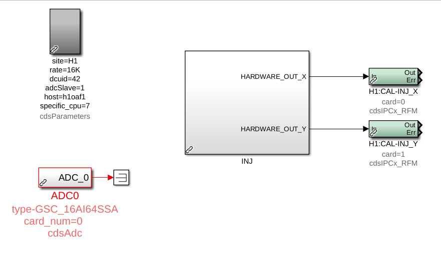
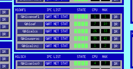
A new h1calinj model has been installed on the h1oaf1 machine. This model will hold all front-end injection handling logic, including the injection EXC test points, under the channel prefix "H1:CAL-INJ_". The existing injection handling code in the h1calex model ("H1:CAL-PINJX_") has been left as is for now to facilitate transitioning and testing.
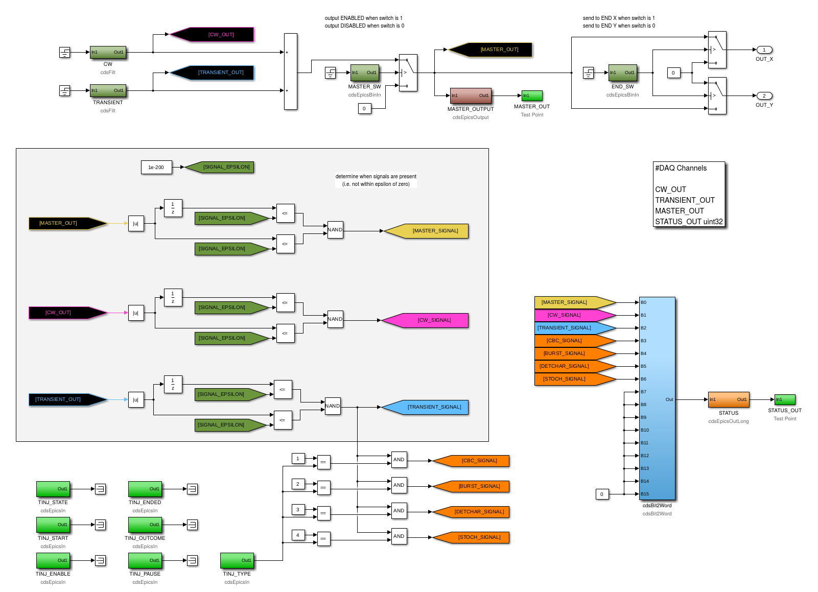
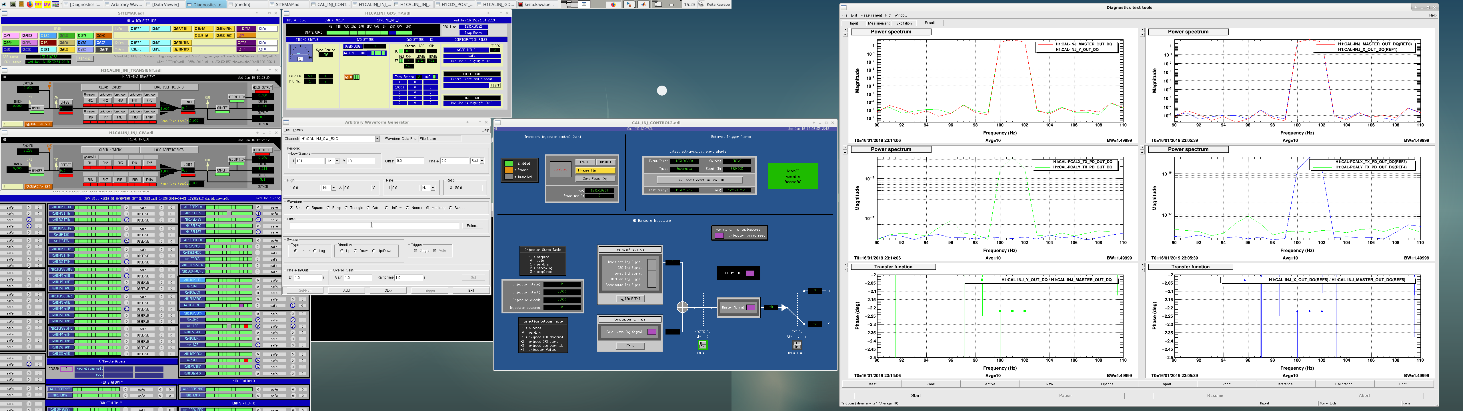
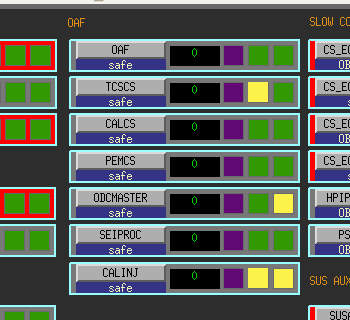
The first two attached images are of the top-level contents of the new h1calinj model, and of the contents of the "INJ" CAL_INJ_MASTER2 library part that contains all the core logic. The top of the latter shows the main injection signal flow. The two "CW" and "TRANSIENT" filter banks at the upper left hold the EXC inputs and calibration filters for the continuous-wave (CW) and transient (TRANSIENT) injection inputs respectively. The outputs of the two modules are summed and the overall "MASTER" output goes through an output switch ("MASTER_SW"), and then finally a switch ("END_SW") that determines which of calex or caley receives the injection signal ("H1:CAL-INJ_{X,Y}" via cdsIPCxRFM). Below the main signal path is logic to determine the presence of signals at various points in the injection path, and bundle that info into a single status word ("STATUS_OUT").
IPC receivers for the INJ_MASTER output sent from h1calinj (H1:CAL-INJ_{X,Y}) were added to the h1calex and h1caley models. EPICS and acquired test point monitors of the received signals were also added.
NOTE: a single 2**14 Hz, 61 us cycle delay will be added to the injection path because of the IPC needed to carry the signal from the vertex to the ends.
The new acquired fast channels are:
The STATUS channels (the H1:CAL-INJ_STATUS_OUT_DQ uint32 fast channel and the H1:CAL_INJ_STATUS slow channel) have the following bits:
A value of zero (0) indicates no signal of the specified type is present, and a value of one (1) indicates the presence of the specified signal.
The h1calinj model also holds the "TINJ" EPICS status bits, nominally set by the INJ_TRANS guardian node. NOTE: the "H1:CAL-INJ_TINJ_" EPICS records were previously hosted by the ext_alert_ioc.py soft IOC running on the h1fescript0 machine. The records were removed from the soft IOC and the process was restarted.
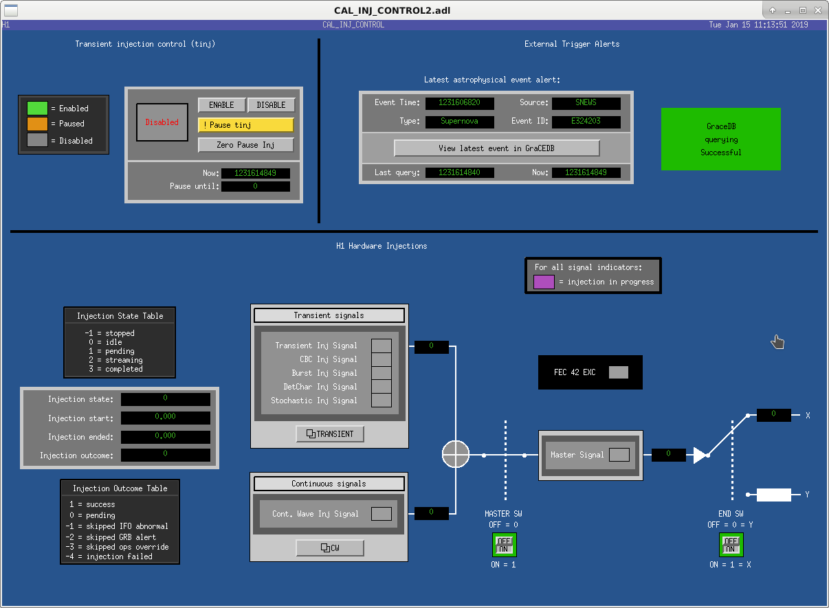
The final image attached is a new MEDM screen CAL_INJ_CONTROL2. All functionality and status bits in the h1calinj model, and the monitors in h1calex and h1caley, are exposed.
As mentioned above, all the existing INJ infrastructure remains in place. We leave it up to the INJ group to update the INJ_TRANS guardian, the psinject process, downstream monitors, etc. We would like to schedule the removal of the old INJ infrastructure as soon as possible,
New MEDM screen is now accessible from the sitemap (cal-> hwinj ctrl). Old one is still there as "hwinj ctrl old".
I briefly tested the new frontend.
No surprise in the above. See the screen shot.
One surprise was that I had some problem loading filters to the new model using foton. Jamie and Rolf are working to figure it out.
(Jamie, Keita)
Existing filters in CAL-PINJX_TRANSIENT filter module were copied over to the new CAL-INJ_TRANSIENT filter and loaded successfully, and the settings represented by the attached screen were put in SDF as safe.
Transient injection group should test the new infrastructure as soon as possible. The new channel to inject is H1:CAL-INJ_TRANSIENT_EXC.
Note that, as of now, the filter is automatically loaded after the model restart as expected, but you cannot reload as far as the model keeps running. CDS group is still investigating, but in the mean time if you need to load the filter, contact the site (e.g. myself) and we'll schedule to restart the model.
I've opened FRS-12175 to cover the problem loading h1calinj's filter file.
Investigation of noise coupling into the EX ESD power supply monitor channels (alog 46038) continues. ESD electronics powered off temporary power supplies.
F. Clara, R. McCarthy, E. Merilh
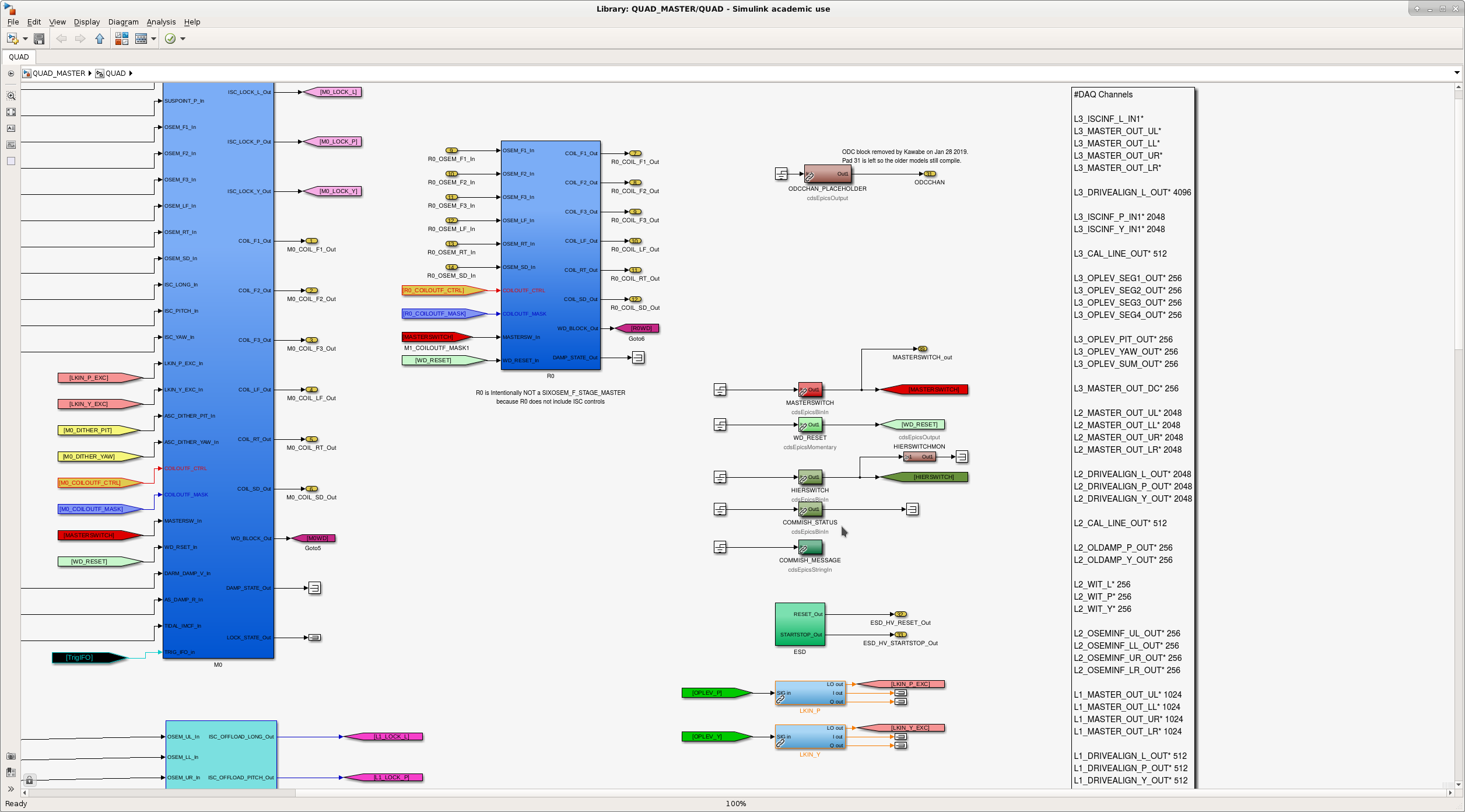
ODC removal (as per ECR 12045) has begun. Summary:
Detailed front end changes:
Further removal of ODC from the rest of the system (ISC, SUS, PEM, etc.) is deferred to later maintenance.
Following models were changed to remove ODC completely and compiled but not installed. Deferred to another opportunity.
h1ascimc (1 IPC sender (PCIE) and an entire ODC block were removed, doesn't use the library, one less fast channel on the frame)
h1pslpmc (1 sender (SHMEM) as well as an entire ODC block was removed from h1 model, ODC-related things were purged from the library, no change in fast channels)
p1psliss (2 receivers (SHMEM) for FSS and PMC as well as two ODC blocks were removed from h1 model, ODC-related things were purged from the library, one less fast channel on the frame)
h1pslfss (1 sender (SHMEM) as well as an ODC block were removed from h1 model, ODC-related things were purged from the library, no change in fast channels)
h1tcscs (1 sender (SHMEM) as well as an ODC block were removed from h1 model, ODC-related things were purged from the library, one less fast channel on the frame)
h1iscex (done by Jamie, no change in fast channels)
h1alsex (1 sender (SHMEM) as well as an ODC block were removed from h1 model, doesn't use library, one less fast channel on the frame)
h1alsey (1 sender (SHMEM) as well as an ODC block were removed from h1 model, doesn't use library, one less fast channel on the frame)
h1lsc (1 sender (PCIE) and an ODC block are removed from the h1 model, doesn't use library, one less fast channel on the frame)
h1omc (1 sender (PCIE) as well as an ODC block were removed from h1 model, ODC-related things were purged from the library, one less fast channel on the frame)
h1pemex (1 sender (SHMEM) as well as an ODC block were removed from h1 model, doesn't use library, no change in fast channels)
h1pemey (1 sender (SHMEM) as well as an ODC block were removed from h1 model, doesn't use library, no change in fast channels)
all SEI models at the end stations (done by JeffK)
Following models are yet to be changed.
all sus models (TBD by JeffK)
Update on Jan 22
During the maintenance on Jan22, the following models without ODC were installed.
h1lsc, h1ascimc, h1omc, h1iscex, h1alsex, h1alsey, h1tcscs, h1pemex, h1pemey.
(h1asc was updated and installed for something unrelated to ODC.)
Remaining frontends that are yet to be replaced with new ones without ODC:
All SUS (models are yet to be changed/compiled).
All end station SEI (models are ready).
h1pslpmc, h1pslfss, h1psliss (models are ready).
Remaining frontends that will be changed again after new HW injection infrastructure is confirmed to work by transient injection group(s):
h1calex (model is yet to be done, PINJX will be completely removed).
h1odcmaster itself (this will be retired).
Update Feb/04/2019
All SUS models were modified to remove ODC, compiled successfully, but not installed. These are:
h1susetmx, h1susetmy, h1susitmx, h1susitmy, h1susbs, h1suspr3, h1suspr2, h1susprm, h1sussr3, h1sussr2, h1sussrm, h1susmc1, h1susmc2, h1susmc3, h1susomc, h1susopo, h1susim (and h1sustmsx and tmsy and h1sushtts on Feb/05/2019)
One PCIE IPC sender and one fast channel were removed per each model, as well as many EPICS channels. One new EPICS channel (ODCCHAN_PLACEHOLDER) was added per each model.
Library parts (QUAD_MASTER, QUAD_ITM_MASTER, BSFM_MASTER, HSTS_MASTER, HLTS_MASTER, OMCS_MASTER, OPOS_MASTER) are still compatible with old models, so if you want to compile any of old sus models with the new library you can. In that case ODC IPC will be plugged to zero.
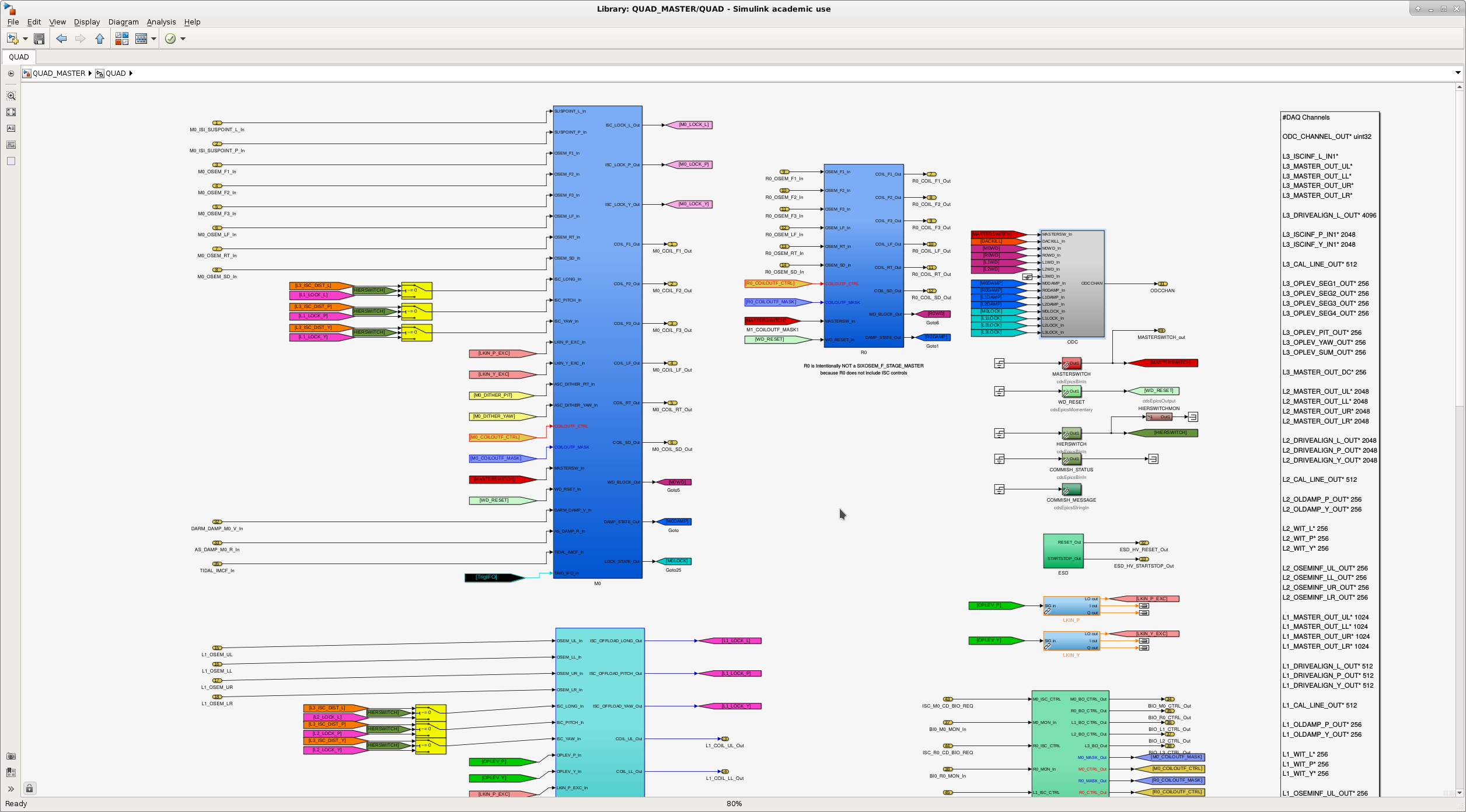
Attached are typical before/after view of the library parts.
Boo. I just assumed that MC1, MC2 and MC3 all use HSTS_MASTER library part, but MC2 actually uses MC_MASTER part. I only edited HSTS_MASTER and individual model (h1susmc1, 2, 3).
As a result, ODC was not completely removed out of h1susmc2. This is going to be fixed in the next opportunity.
Keita and Rahul Keita showed me how to make changes to the front end model of SUS. We made changes to MC_MASTER library parts to remove ODC. We complied h1susmc2 successfully, however we didn't install it.
I swapped out IO_MB_M3, which is a 2 inch steering mirror just before the power rotation stage at the North end of the PSL. The new optics position was slightly different than the old optic's position. I used my GigE cameras and the single bounce of IMC_IN off MC1 to the IMC WFS, to restore the alignment of IMC_IN.
Here are the changes in the IMC, measured by how many urads the three IMC mirrors moved, and what that calculates to be in mm.
| 15 Jan 2019 | 9:00 UTC | 21:13 UTC | |||
| optic DOF | urad | urad | diff urad | rad | mm |
| mc1 p | -299.2 | -300.36 | -1.16 | -1.16E-06 | -0.05 |
| mc1 y | -1000.5 | -1001.2 | -0.70 | -7.0E-07 | -0.03 |
| mc2 p | 138.7 | 139.3 | 0.60 | 6.0E-07 | 0.05 |
| mc2 y | 629.9 | 629.2 | -0.70 | -6.9E-07 | -0.01 |
| mc3 p | -651 | -652 | -1.00 | -1.0E-06 | -0.05 |
| mc3 y | -1281 | -1279 | 2.00 | 2.0E-06 | 0.09 |
Changes in the beams on the cameras are listed below:
NOTE: GigE 1 is the PMC Trans beam, and due to temperature changes it's beam changed, which influences the beam positions on the other two cameras.
| 15 Jan 2019 | 9:00 UTC | 21:13 UTC | |
| pixels | pixels | diff_pixels | |
| GigE 1 x | 329.5 | 329.8 | 0.30 |
| GigE 1 y | 159.9 | 160.85 | 0.95 |
| GigE 2 x | 325.3 | 325.6 | 0.30 |
| GigE 2 y | 247.2 | 251.8 | 4.60 |
| GigE 3 x | 271.7 | 267.2 | -4.50 |
| GigE 3 y | 274.3 | 280 | 5.70 |
The camera image pixels have not yet been calibrated, so that they can be displayed in either mm, or possibly the angle change.
Robert added damping to the bottom periscope mirror and IO_MB_M3 during this time.
As time was limited, I'll plan to add a picture of IO_MB_M3 next week.
- Cheryl, Robert
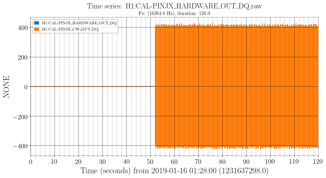
Restarted CW hardware injections at GPS 1231624918 (Jan 15 2019 22:01:40 UTC). They seem to have crashed on January 8 (maintenance disruption?). It would be good to get monit running so that restarts occur automatically.
I've opened FRS12139 to cover this.
Greg will first upgrade h1hwinj1 to SL7.6 before we install/configure monit and its web interface.
CW injections re-restarted at GPS 1231637350 (Jan 16 2019 01:28:52 UTC) after Greg's upgrade.
A few weeks ago I noticed my daily build was reporting adcparser errors with h1asc. The parts array was of fixed size=5000 and h1asc had grown to about 5200 parts. I increased the limit to 6000.
Yesterday I noticed the error had come back, and sure enough h1asc had grown to 6894 parts. As a side note, this seems to be a rather large increase in a short amount of time.
I have bumped up the limit from 6000 to 10,000
I'd never heard of this parts limit before. The smooth limiters (which have now been put in on the inputs of the ADS servos, since we're using them as part of the ASC system more now) have about 100 parts per limiter. There are 10 each of pitch and yaw loops in the ADS system, so today I added about 100*20 = 2000 parts (if you count "GoTo" and "From" flags, and mux and demux all as individual parts). This work was done as part of WP 8047.
Since we were booting the ASC model anyway for this work, Keita pulled all of the ODC parts out of the ASC model.
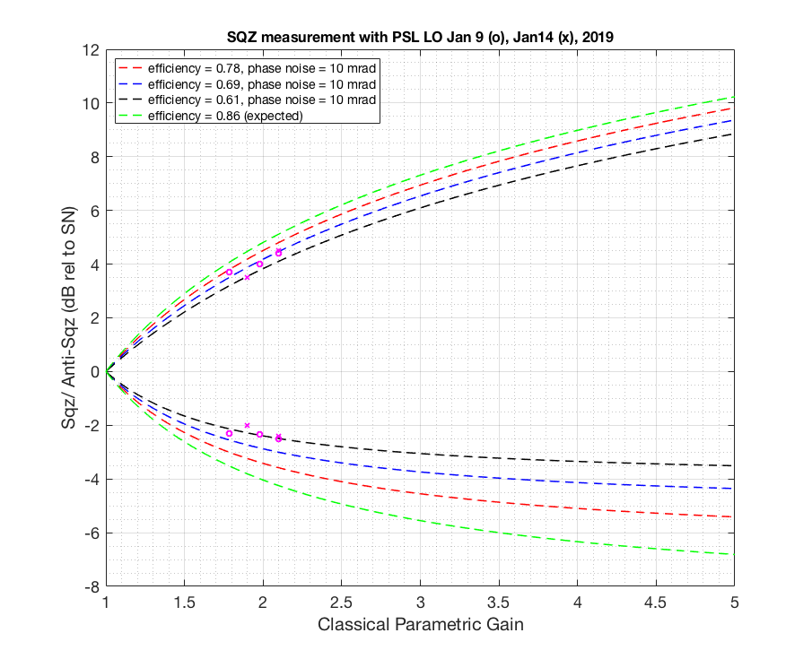
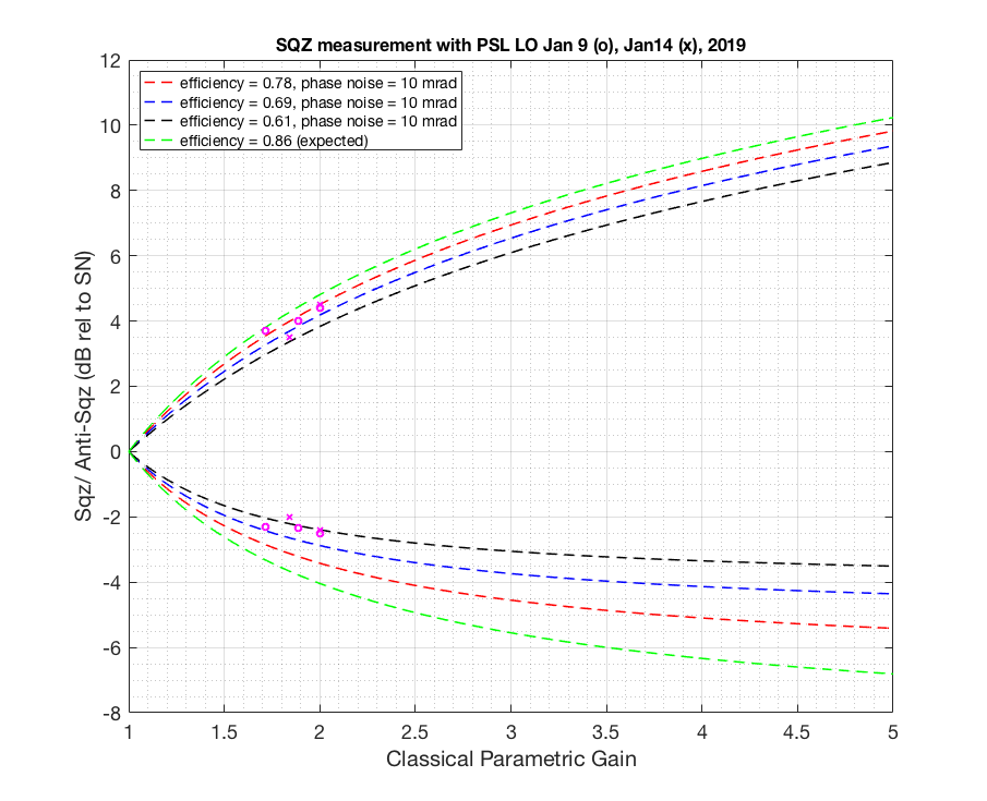
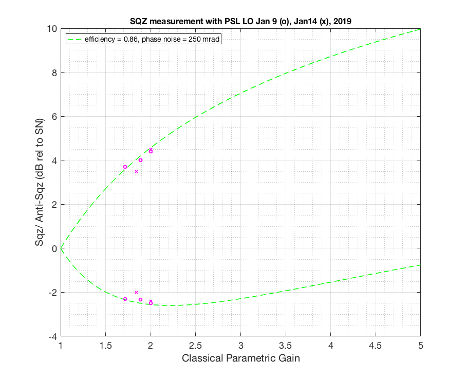
Previously in alog46336 I felt like I was bottomed out on some of the measurements phase delay wise. To get more phase delay so we can be more confident in our measurement I gave 3MHz phase delay box to CLF (I have a feeling that phase delay box hooked up to LO/OMC gives me a bit less phase, not sure if that make sense, I will post more detail alog on the ellipse rotation later). Add CLF sign flip on top of that (which gives us extra 90 degree as Daniel suggested) I was able to go from OK to GOOD then back to OKAY measurement on both squeezing and anti squeezing. Flipping LO sign didn't help (180 deg). And using Q error signal to lock the CLF seems to have given me some extra phase adjustment (not sure why, CLF common mode board input 2 now has Q error signal goes into it). This way I know that I've seen the best sqz/asqz (by monitoring LO Q error signal go up and down while adjusting the phase, we locked with I).
After correcting for some of the minor loss typos and added data taken yesterday after I've acquired more phase delay, here I attached another loss estimate plot. I also give phase noise of 10 mrad this time since assuming that what we measured out of the LO IMON isn't all the phase noise there is. The result hasn't changed. We have more loss compared to when Haocun took a measurement here. We are still in the process of checking red transmission then and now.
Fringe visibility during Jan14 measurement was 99%. In the model I use 97%.

Before the measurement our laser was running multimode again. To get away from multimode I moved the current knob from 2.193A to 2.207A. Temperature stays the same (29.65C). This gives 158MHz without having to put a lot of offset to the control loop (ended up with -7MHz).
I went back to double check if my nlg was correct and found that the dark noise was actually negative (I missed a minus sign when I subtracted the DN). So here attached a revised plot. That didn't change the result (sadly). I also attached a plot projecting how much phase noise would you need in order to explain what we observe if we were to let efficiency by 86%. You need at least >250 mrad to explain what we have (which is not what we observed in LO error signal).


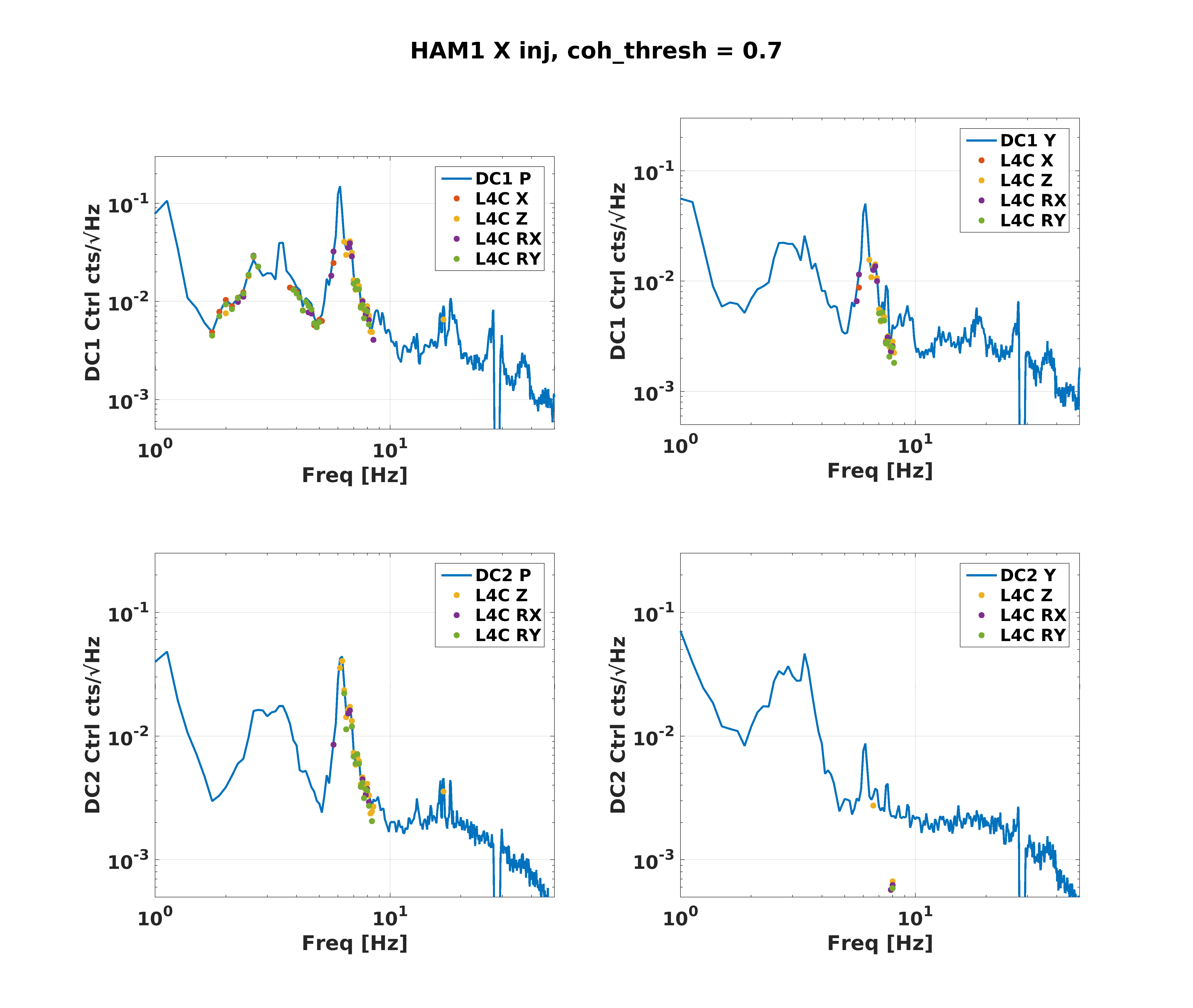
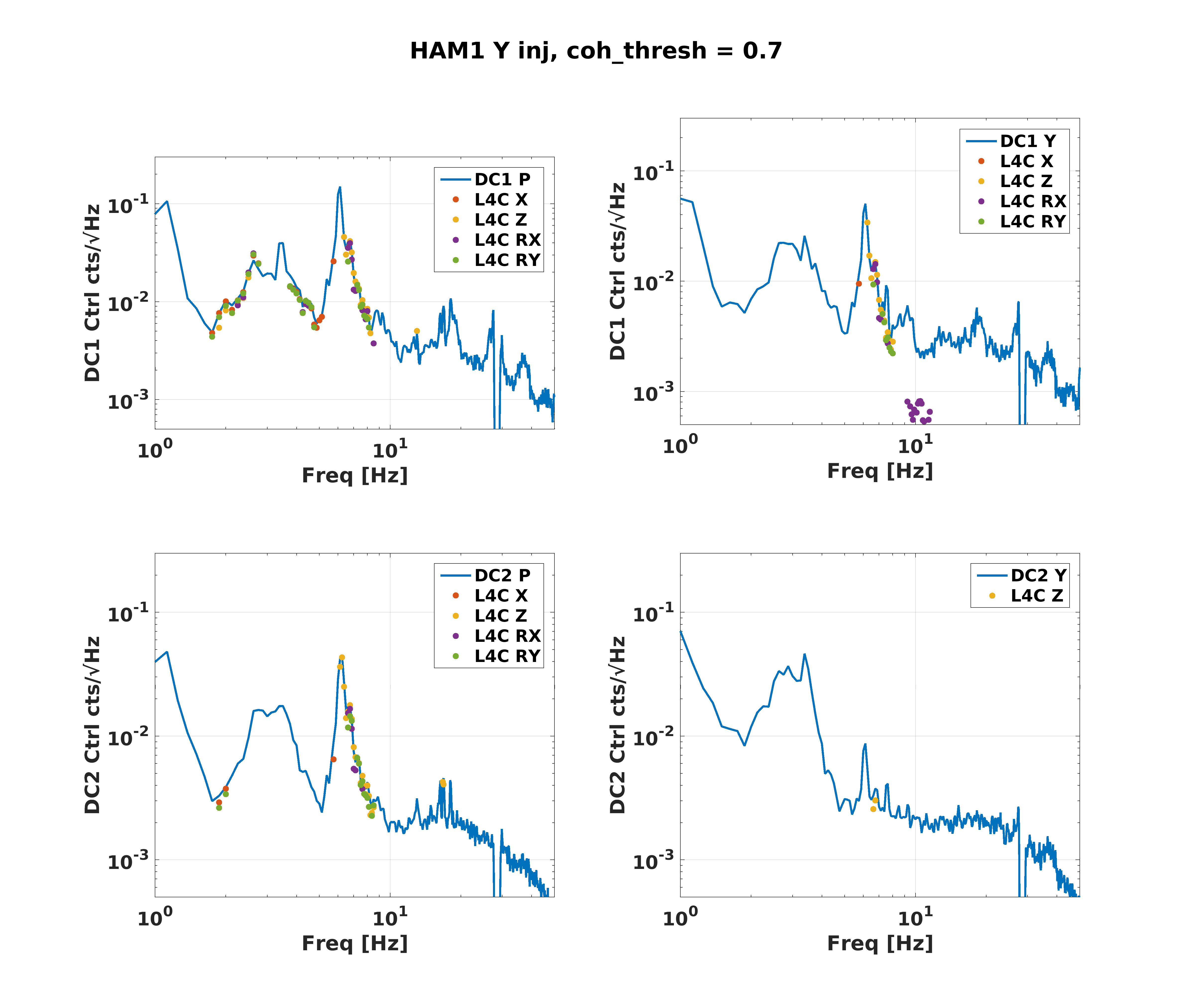
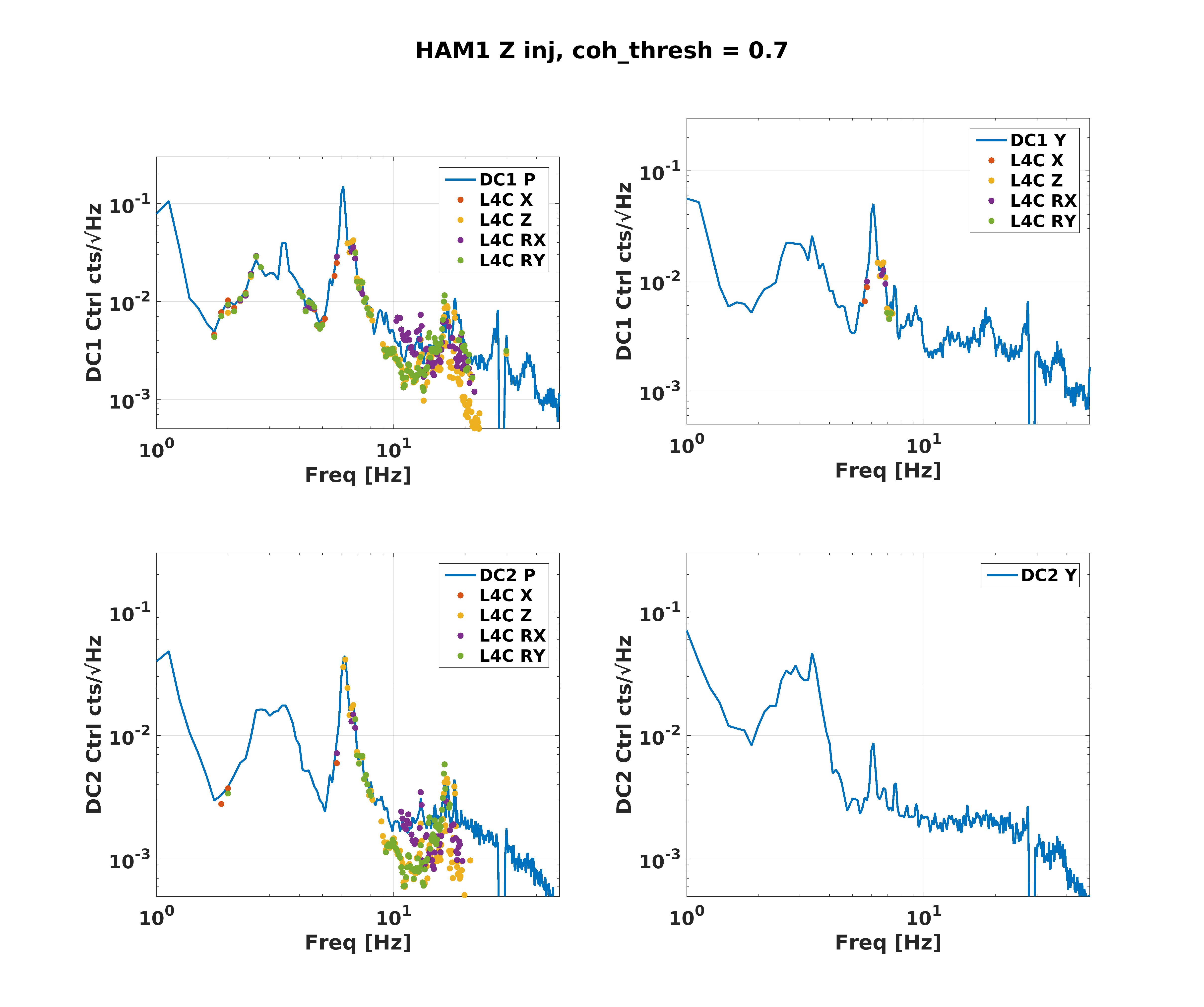
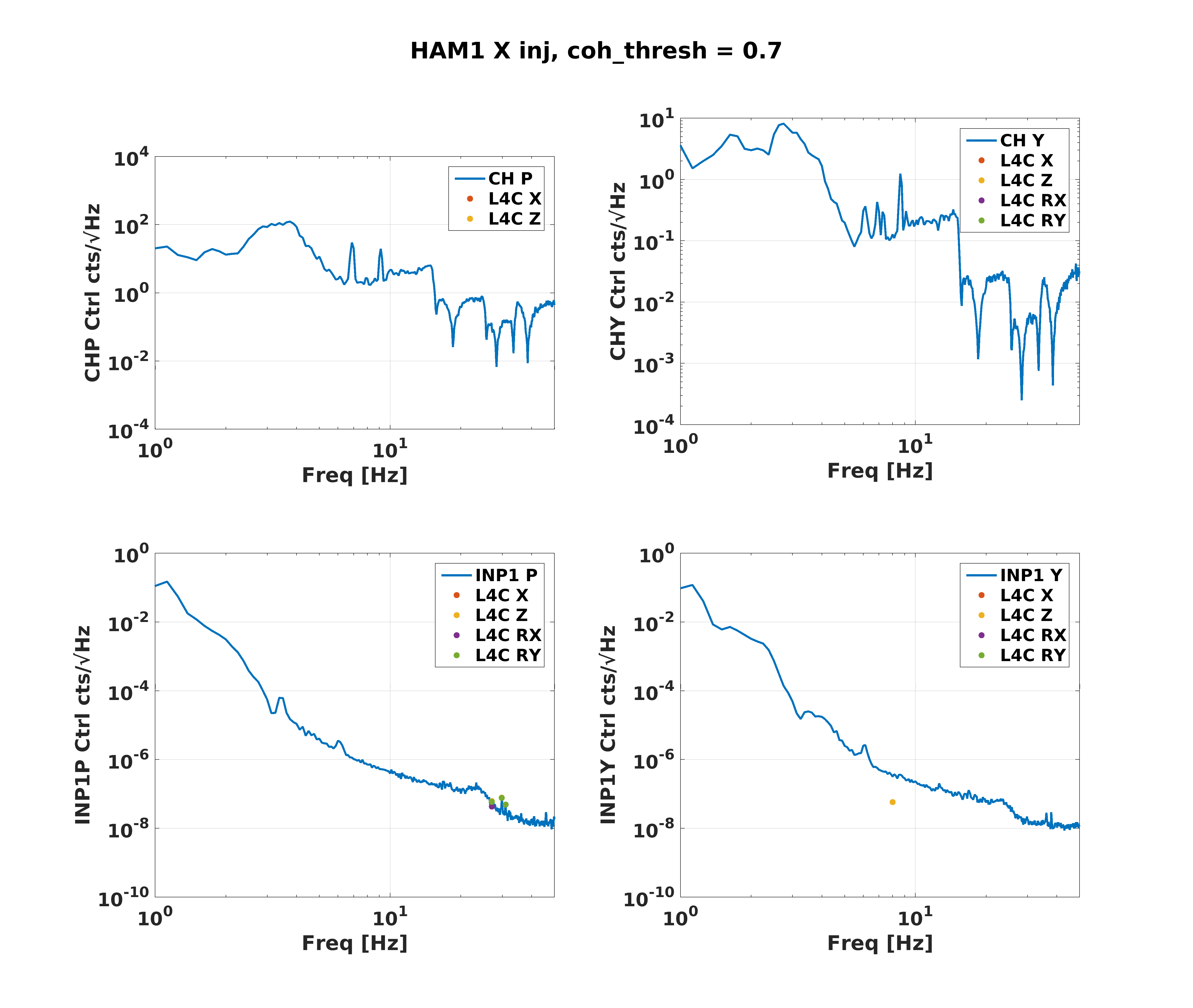
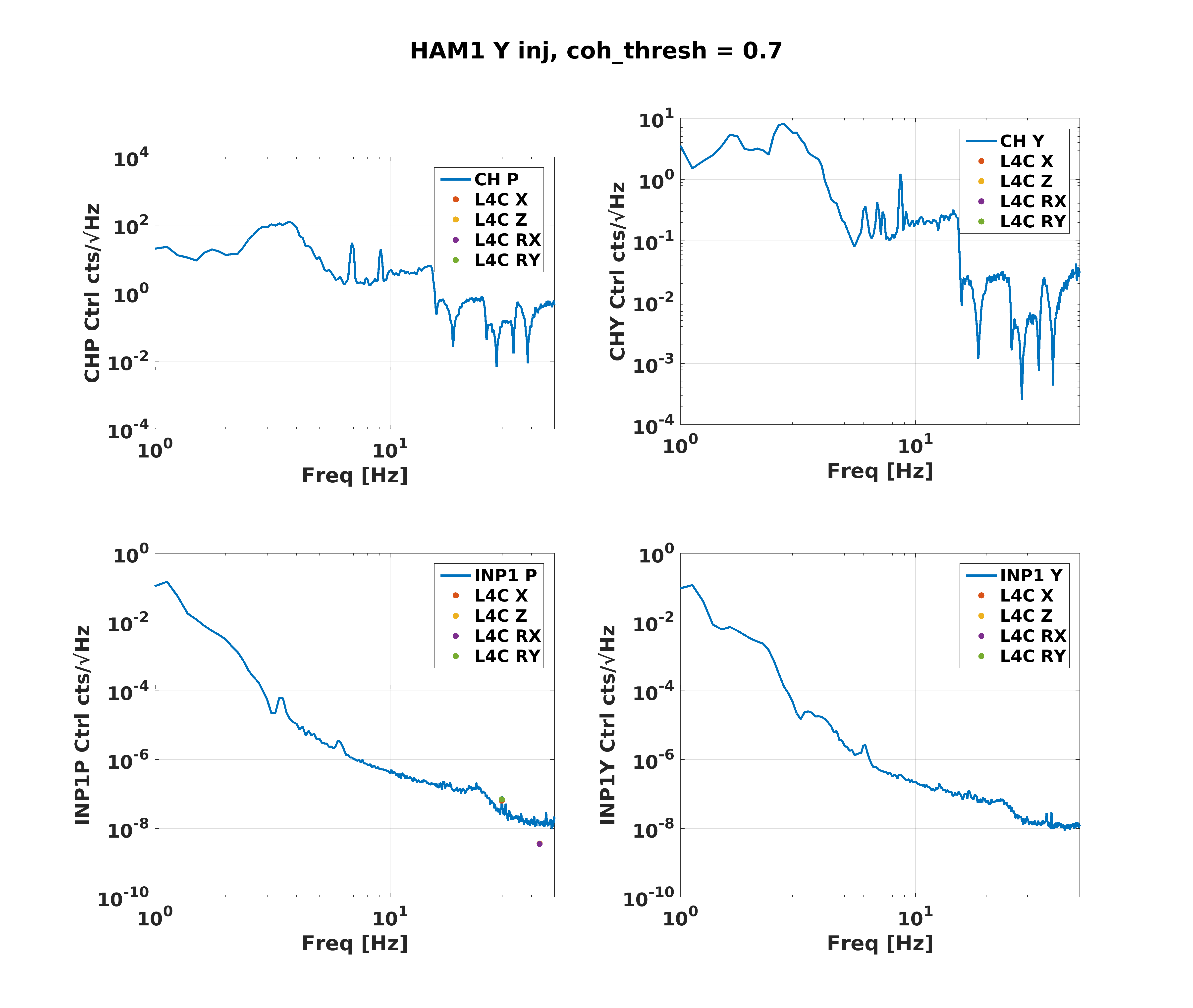
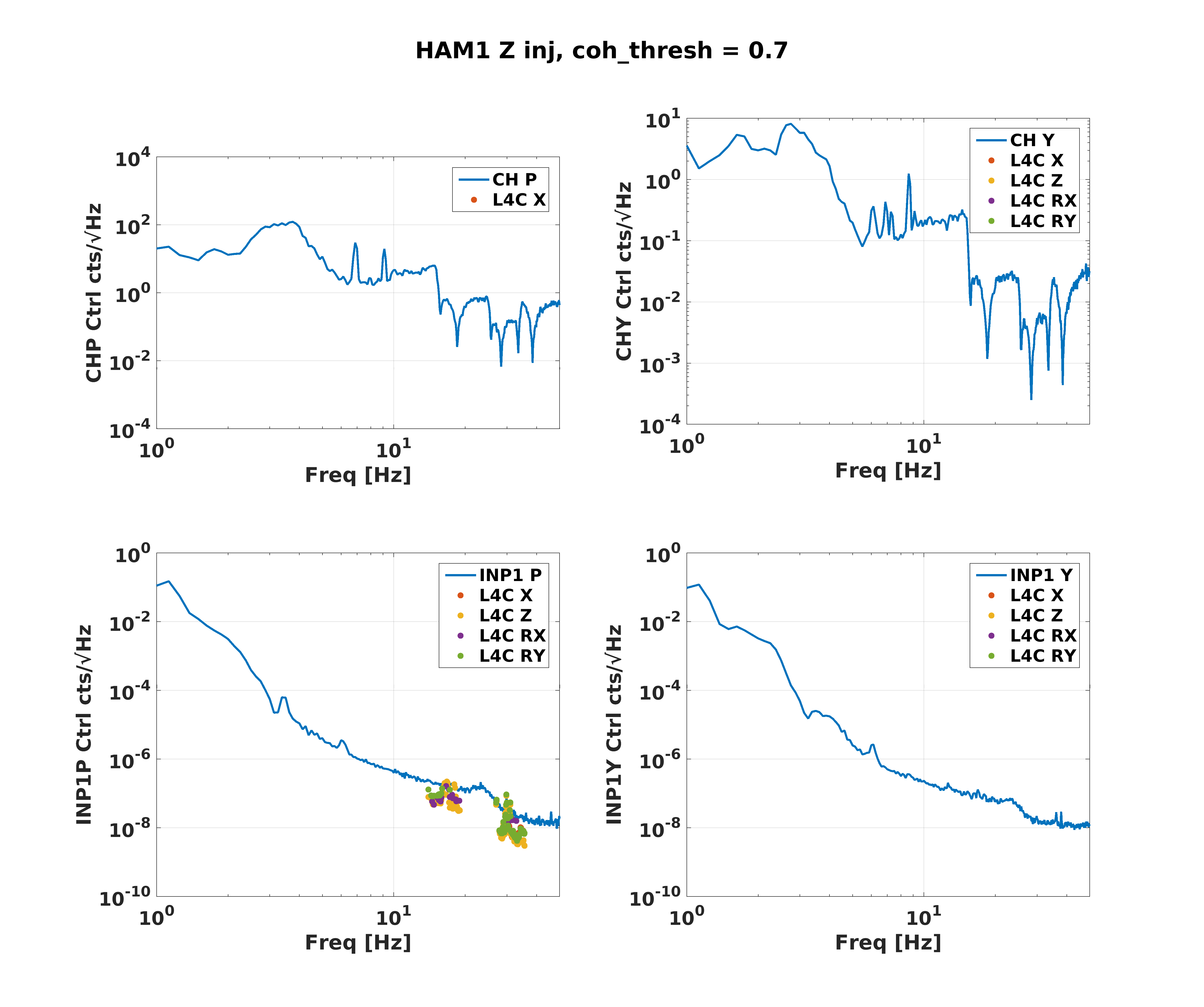
I did some injections on HAM1, for comparison with 42694 and 42722
I reduced the amplitude compared to 44856, so these excitations aren't showing up in DARM, but people can look for them in the REFL WFS and table top L4Cs.
The Z excitation started at 2:11:50 UTC, was stopped after a large glitch at 2:23 UTC Jan 15th.
The X excitation started at 2:27 UTC, but there were several large glitches. a relative glitch free time was from 2:37-2:44, the excitation continued until 2:44 UTC.
The Y excitation started at 2:55 UTC, and was on until 3:06. We had to turn the dither lines back on partway through that because the PRC1Y was slowly going unstable.
I know Gabriele is looking at how these compare H1 vs. L1, but just a preview of how much HAM1 motion is affecting our ASC signals...
I've taken the times that Sheila posted above, and gotten the transfer functions from the tabletop L4Cs to the different ASC degree of freedom control points (they are saved at a faster rate than the error points, although the error points are easier to calibrate). Then projected the quiet non-injection tabletop motion onto each degree of freedom.
Attached are 6 plots, looking at the DC centering loops and the WFS (CHARD and INP1), for the 3 different injection directions. The WFS themselves don't really see much with the table motion, but the DC centering loops in pitch are seeing a lot of this table motion. This is in contrast to LLO, who needs to use the tabletop L4Cs to feedforward to CHARD. None of the table motion is affecting the centering loops above about 20Hz. The L4C projections are only displayed in the plots if there is anywhere in the transfer function that has coherence during the injection above 0.7.
The ability to feedforward the L4C signals to the ASC has not yet been implemented, since without that data it wasn't clear which DoFs needed it the most. LLO hard-codes the ability to feedforward to CHARD only, which we don't want to do since that's not a degree of freedom that is bothered by the table motion. Note however that the sender parts are now in the SEI model, so if we decide to implement feedforward, it will only require an ASC restart, not any SEI restarts.
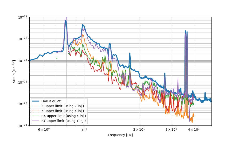
Since the injections are not strong enough to be seen in DARM, all we can do is compute upper limits, as shown below.
Dan, Hang
Using the dithering lines we set up for the past few days for sensing matrix measurement, and the suspension calibration provided in DCC:T1100378, we calibrated the spectra of the ASC error points into physical rad/rtHz. The results were attached.
The best sensor we have is AS45 for DHARD, and the sensing noise is ~ 1e-14 rad/rtHz. While a single QPD has a sensing noise similar to AS45, when we use a QPD combo for CHARD to decouple CSOFT, the sensing noise get slightly worse at ~ 3e-14 rad/rtHz level. The soft loops' sensing noise is about a factor of 10 higher than the hard loops at a few x 1e-13 rad/rtHz level.
On the other hand, the REFL sensors are significantly noisier than AS45/TR QPDs. Using the REFL sensors the CHARD sensitivity is only 1e-12 rad/rtHz at 10 Hz and the slope suggests that it is not shot noise limited. This indicates the necessity of doing CHARD blend from the noise point of view.
For future reference, the calibrations are (from L3 physical angle times the output matrix, to the error point of each dof after the input matrix).
DHARD PIT: 6.8e+10 [ct/rad]
DSOFT PIT: 1.0e+5 [ct/rad]
CHARD YAW (DC, REFL combo): 2.0e+10 [ct/rad]
CHARD YAW (AC, TRQPD combo): 4.3e+10 [ct/rad]
CSOFT YAW: 2.1e+5 [ct/rad]