I did some injections on HAM1, for comparison with 42694 and 42722
I reduced the amplitude compared to 44856, so these excitations aren't showing up in DARM, but people can look for them in the REFL WFS and table top L4Cs.
The Z excitation started at 2:11:50 UTC, was stopped after a large glitch at 2:23 UTC Jan 15th.
The X excitation started at 2:27 UTC, but there were several large glitches. a relative glitch free time was from 2:37-2:44, the excitation continued until 2:44 UTC.
The Y excitation started at 2:55 UTC, and was on until 3:06. We had to turn the dither lines back on partway through that because the PRC1Y was slowly going unstable.
J. Kissel
Since it looks like we're sticking with using ETMX for all stages of DARM actuation, I've switched the CAL lines for the UIM and PUM (L1 and L2) stages to being driven from ETMX. For now, I've left then at the same frequencies they were before (15.1 and 16.7 Hz), instead of the recommended line frequencies from Joe earlier today. After I
- get a new set of calibration sweeps to update the front-end calibration for a 30W IFO, and for full ETMX actuation (hopefully tonight)
- update the front end
- generate new EPICs records for the time-dependent correction factors
then I'll switch to the line frequencies Joe suggests.
I've accepted this into the SDF.
TITLE: 01/15 Day Shift: 16:00-00:00 UTC (08:00-16:00 PST), all times posted in UTC
STATE of H1: Commissioning
INCOMING OPERATOR: None
SHIFT SUMMARY:
LOG:
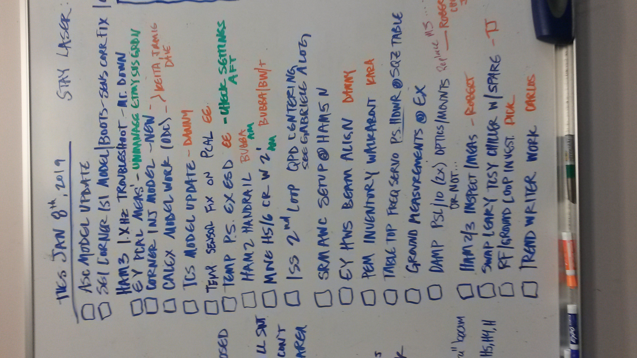
Schedule as of the end of the meeting, for 15 Jan 2019: Tentative
Activities:
Images of the very full white board attached.
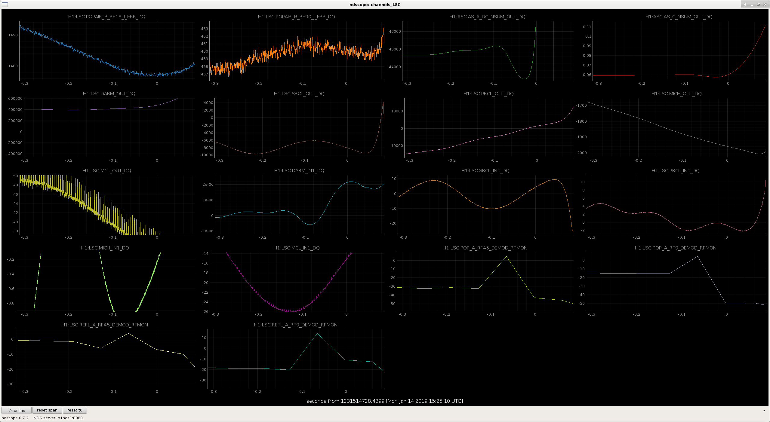
During the several hour lock over night, that I found the IFO in this morning there were some strange combs in the CARM signals.
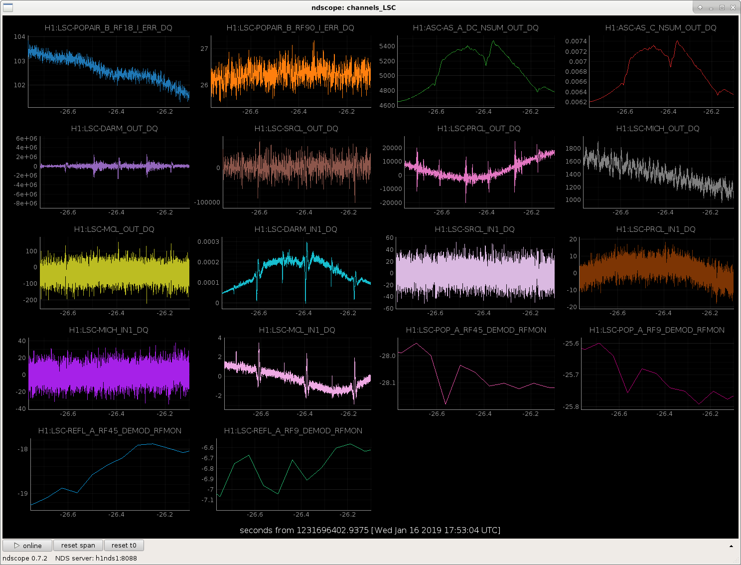
The particularly strange thing is that I see these spikes in the LSC-MCL signals for that lock first thing this morning, but haven't really seen them in any later locks today. During the lock that the spikes are there, there are a few times that the spikes go away for 2-4 sec, but they always came back. In the next lock, the spikes were almost never there, but did come in 2 or 3 times for 1-2 sec, but then went away again. Between these 2 locks, I'm not aware that any configuration changes were made to the CARM system.
The SR785 was plugged in to the IFO common mode board, and the excitation input was enabled, so it's possible that the SR785 and whatever mysterious grounding problems we've been having are the culprit. But, since the SR785 wasn't unplugged until much later in the day, I'm not so sure. Anyhow, we're going to try to make a habit of unplugging any instruments from the ISC racks as soon as a measurement is complete, just in case.
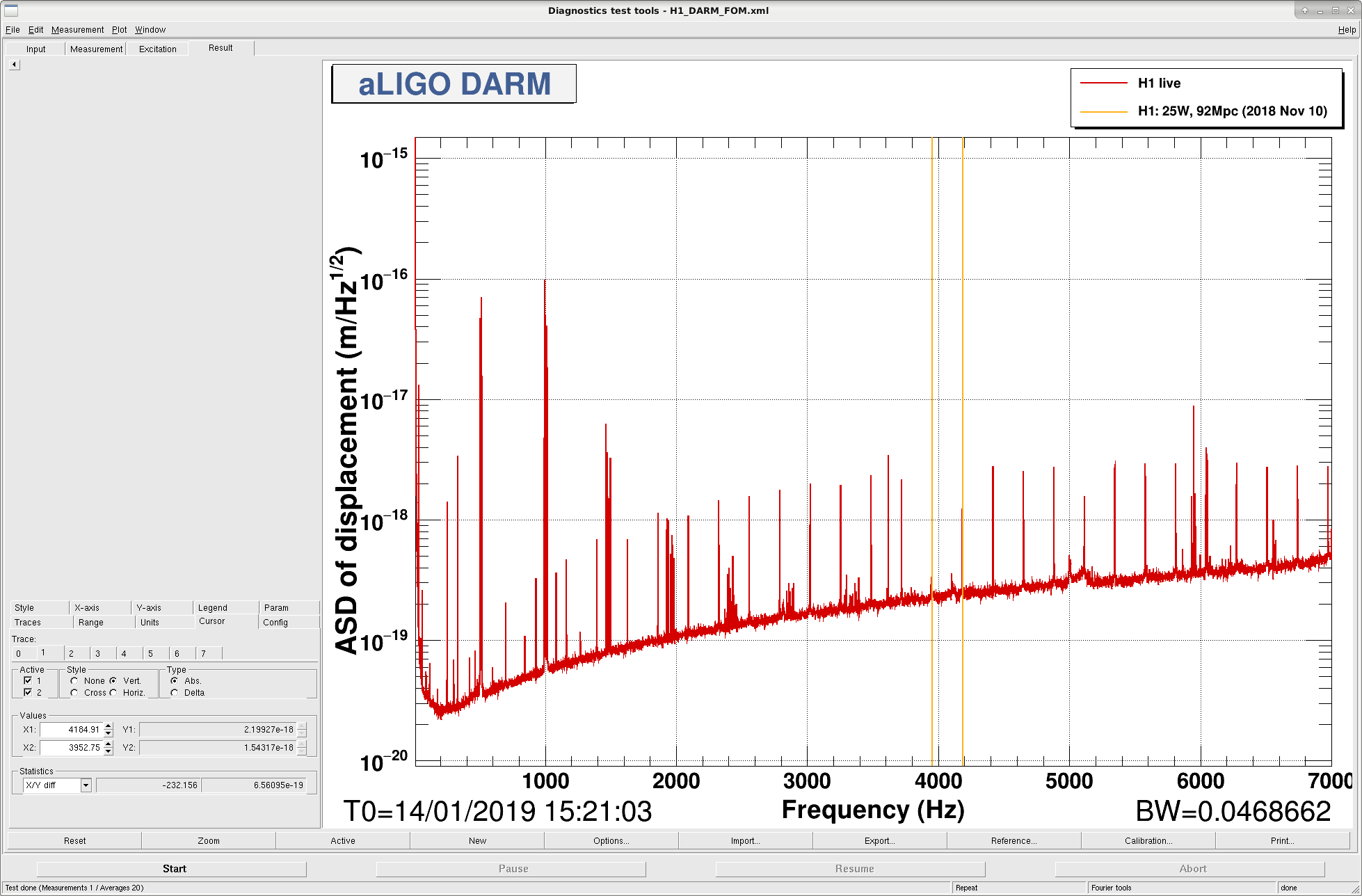
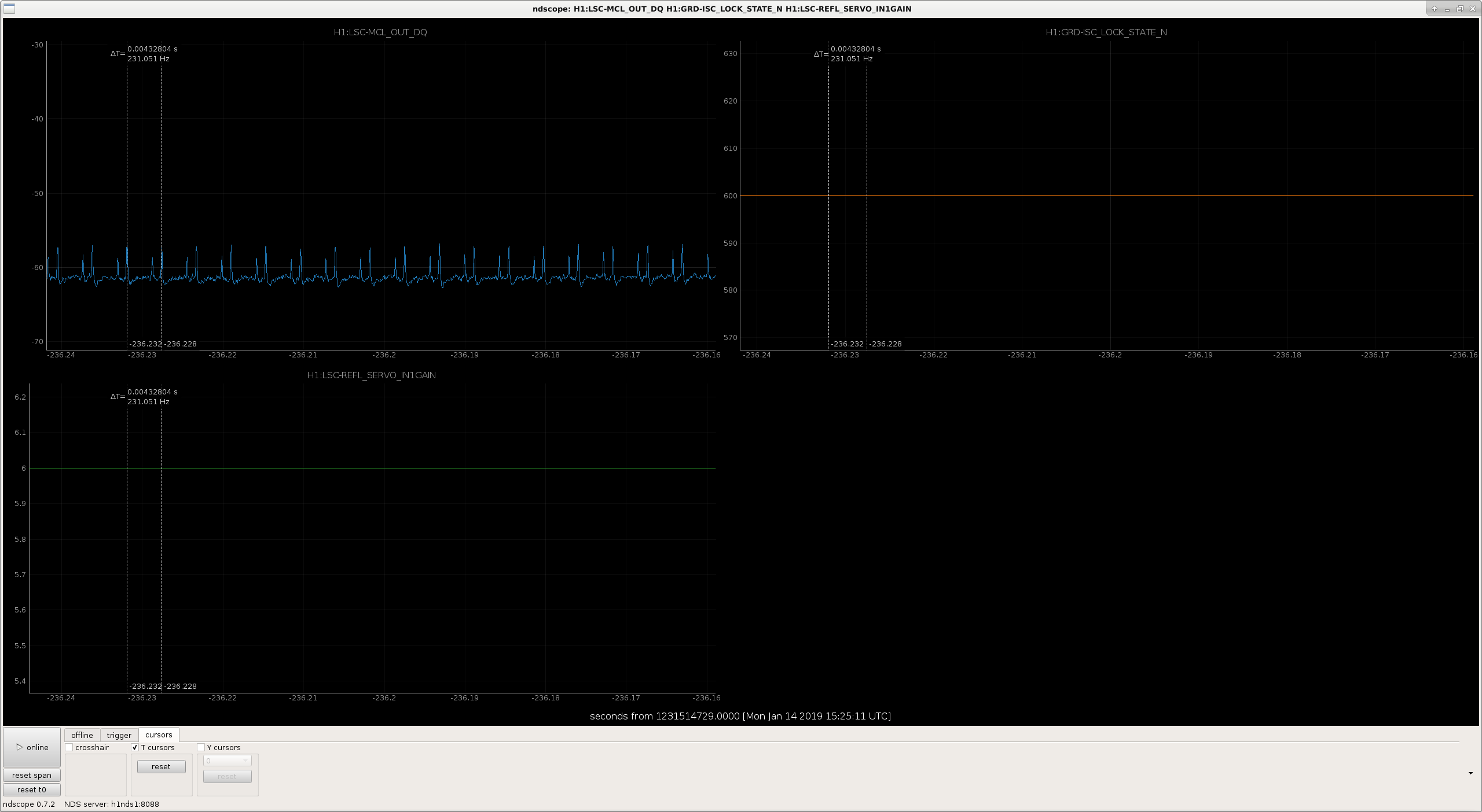
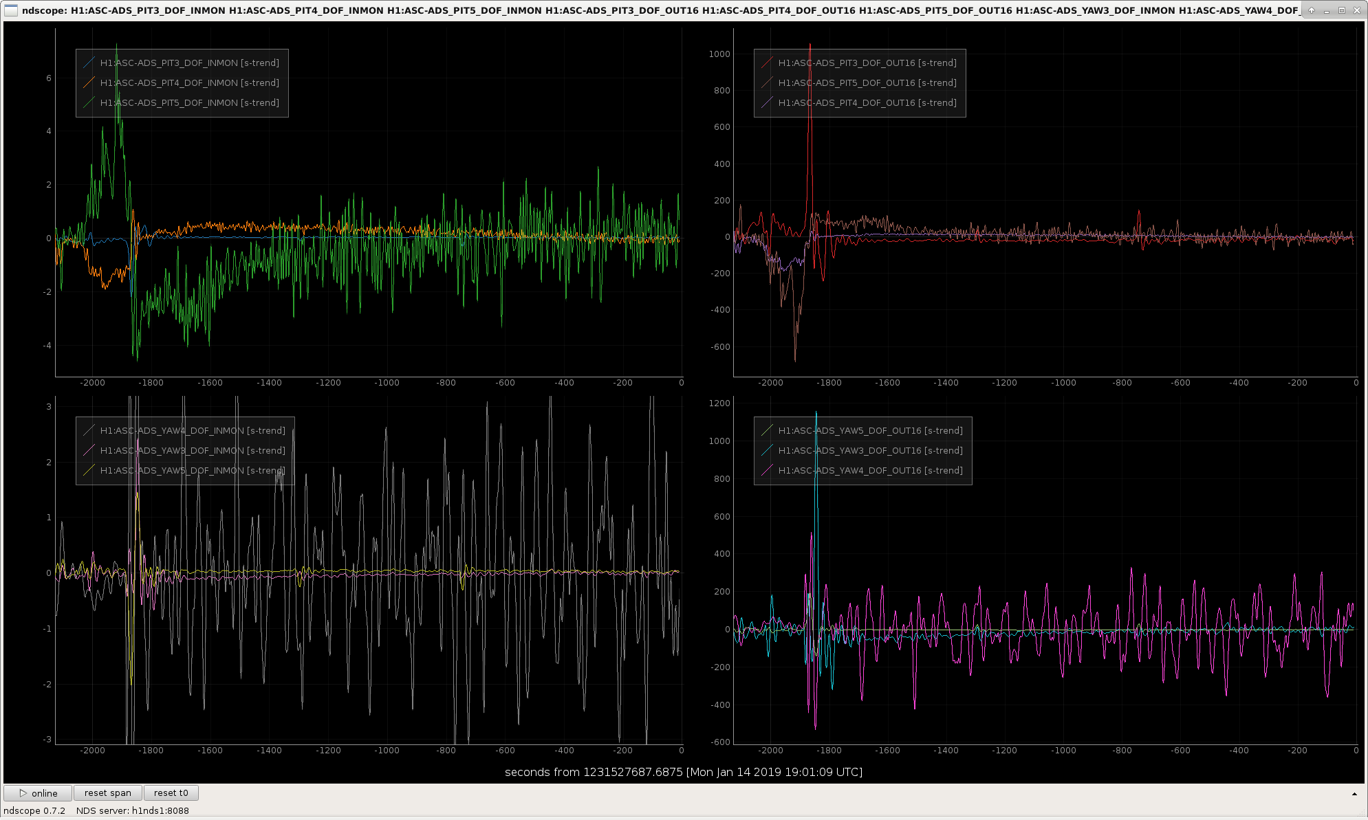
It looks to me like there are 2 different combs, both very near 232 Hz, but they are drifting in time relative to one another. See attached DARM spectrum with the giant comb, as well as ndscope screenshots from 2 different times during the same lock. The ndscope screenshots also show that the IFO is in the same state (NomLowNoise) for both of these times. No gain sliders in the common mode or IMC servo boards were being moved either.
These spikes could be causing me to repeatedly lose lock when I try to transition DARM to RF (CARM is already on TR at this point). The spikes that I see in MCL are also showing up clearly in PRCL, and are definitely present in DARM.
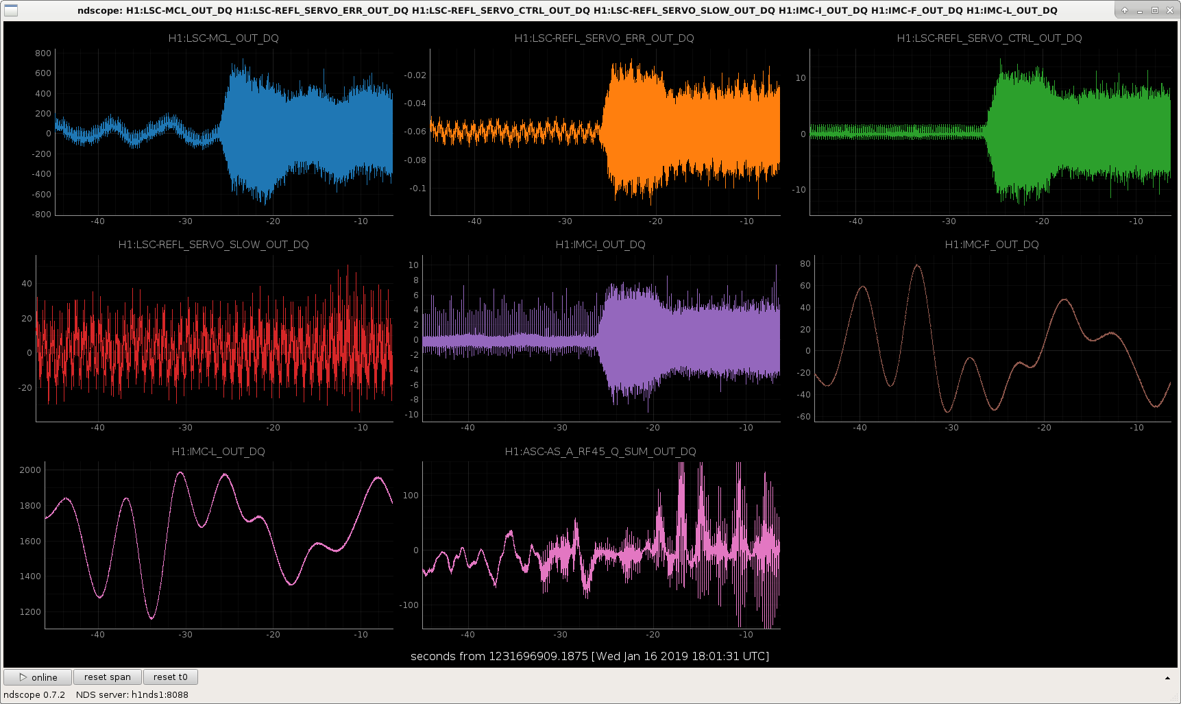
UPDATE: The second figure is from a time when I'm transitioning CARM off of the ALS signals and onto the IR transmissions. During this time, the spikes begin to be impressed on AS45, which is the signal that we'd use in the next step for DARM. So, the AS signals don't have the spikes natively, but they do show up once the spiky signals are used for CARM.
Also, both the SR785 and AG4395 were plugged into the CARM and IMC boards respectively. I had ndscope open on the workstation by the racks, and was watching the spikes while the IFO was locked on ALS, with DRMI locked. When I wiggled the cable connections at the analyzers, I did not see any effect on the spikes. I then unplugged the IN2 cable from the IMC board (at the chassis), and saw no change. Next I unplugged the EXC cable from the IMC front panel, and the spikes immediately went away. This was repeatable, re-introducing the cable brought the spikes back, removing the cable removed the spikes. Note that the excitation point on the board was disabled, but somehow the Agilent is still causing noise. It didn't look like the Agilent was taking any measurement, it was just passively plugged in. I unplugged the 3rd cable from the IMC chassis, as well as all 3 cables from the CARM common mode board just for good measure. The SR785 and AG4395 are still on, but they are not cabled to any IFO electronics.
With the SR785 and AG4395 unplugged, I do not see regular spikes on MCL. However, when doing the CARM and DARM to IR transitions, I did see the spikes come back for a few seconds, but then they're gone again. So, there may still be something going on (does the Agilent need to be turned off entirely?), but it's much better now. I have not had any trouble locking since.
Moral of the story - we can't leave the AG4395 plugged in to the IMC common mode board, even if the excitation input is disabled. Needing to turn the RF analyzer off, or also forbidding the SR785 is still a possibility, but not yet proven.
Separately, while I was standing next to the ISC racks, I noticed that if I took a step (heavy step, but not stomping) I could see a buzz of noise in both the IMC signals and AS45, despite our still being locked entirely on ALS for the arms. I did not check how close / far I had to be from things to see this, but if we're getting a big burst of noise just from walking with anything but the most gentle of steps, perhaps that's a clue we can use to figure out why we are so sensitive lately.
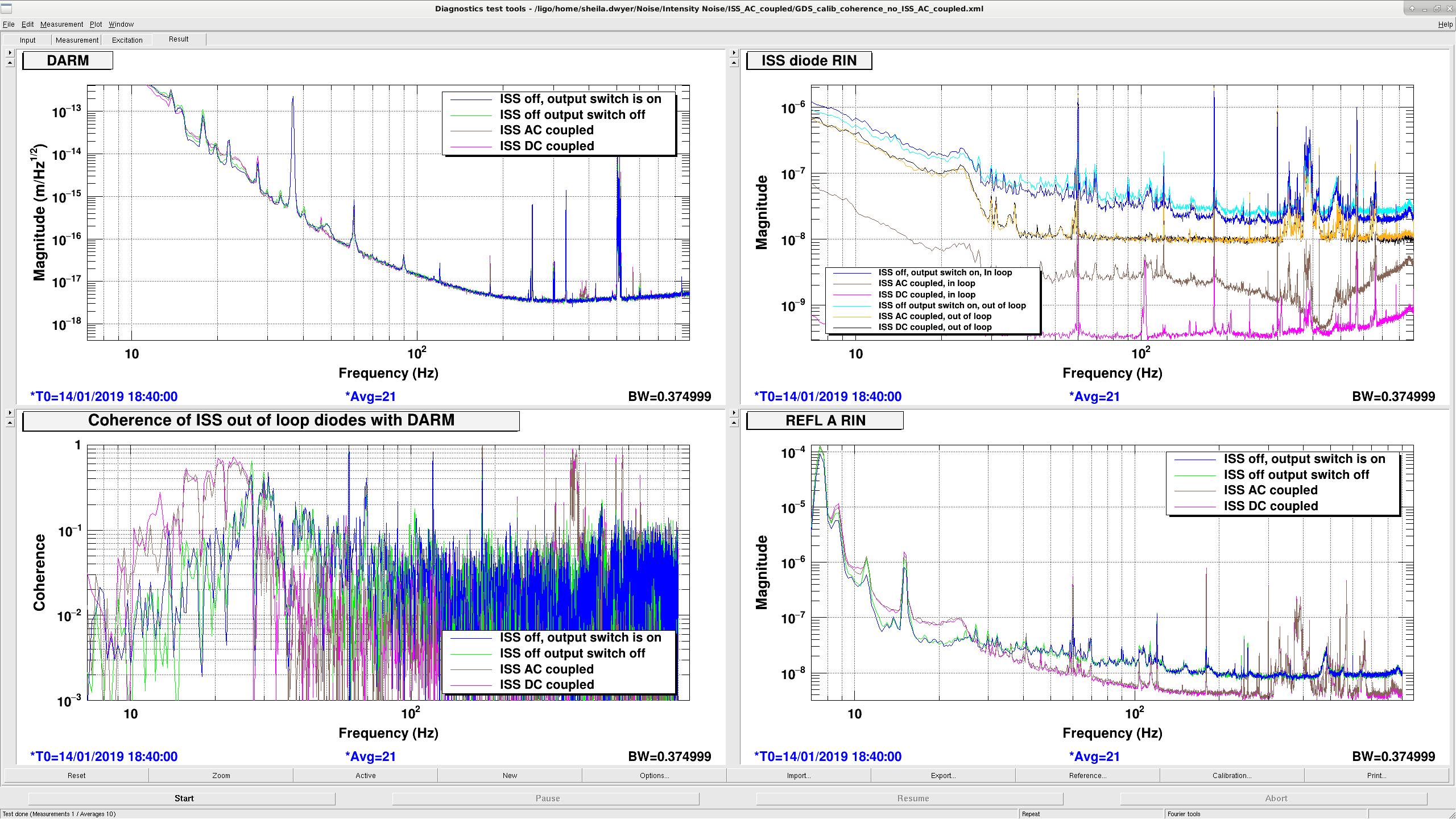
As Danny reported on Friday 46382, the HAM2 motion coupling to DARM that Robert noticed 46373 is coupling through the ISS second loop, and there is also strong coherence with DARM below 30Hz.
Dany and I used data from several different locks on Friday, and we couldn't make a good comparison of the low frequency noise in DARM because some of those locks had large scattering or other low frequency problems. This morning Keita Jenne and I got about 10 minutes of data with the ISS second loop in 4 different states while the interferometer was in low noise:
| second loop off, output switch on | Jan 14th 2019 18:38 UTC |
| second loop off, output switch off | 18:48 UTC |
| 2nd loop AC coupled | 18:59:30 UTC |
| 2nd loop DC coupled | 19:17 UTC |
The attached DARM spectrum shows that the ISS was adding noise to DARM both at 25Hz and below and from 350-400Hz. The coherence of the ISS out of loop diodes with DARM is pretty much the same weather the second loop is AC or DC coupled. REFL RIN also indicates that the intensity noise imposed by the second loop is the same for the AC coupled or DC coupled ISS.
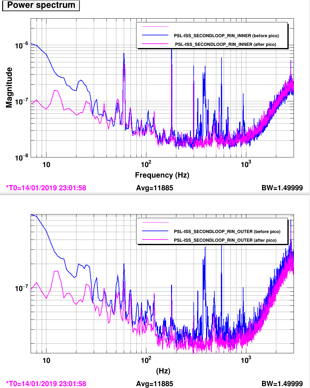
Georgia and Danny have pico'd the array to fix this.
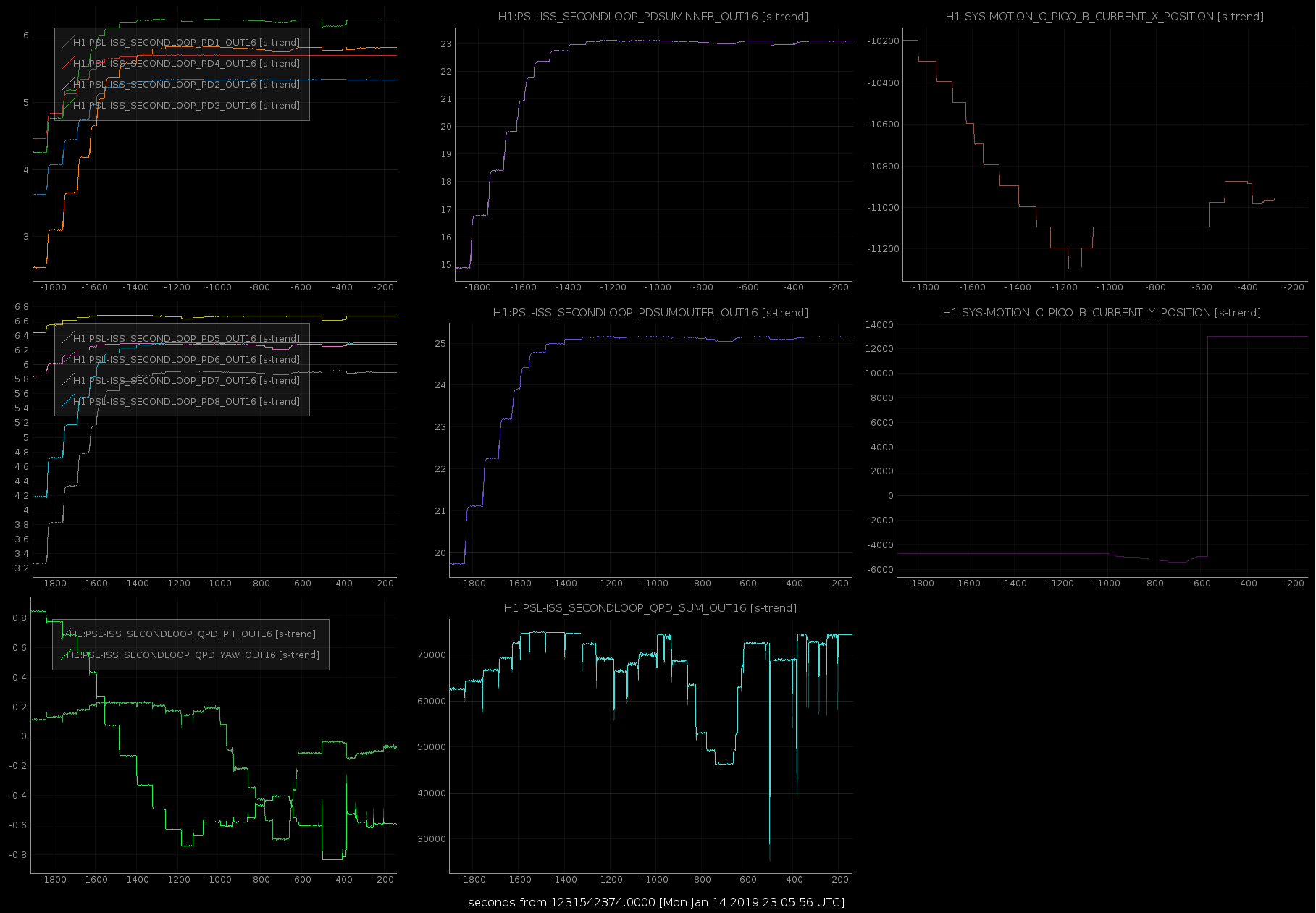
We pico'd onto the ISS second loop QPD and PD arrays. We have improved the RIN on both the inner (in-loop) and outer (out-of-loop) PD arrays (first attachment), and the alignment onto the individual photodiodes and the QPD (second attachment).
Gabriele last centred the beam on the array last year. There are two picomotor mirrors on the path from IM4 to the ISS arrays, we adjusted both PM1 and PM5, but mostly PM1. We did this pico'ing with the IFO unlocked, and the power through the mode cleaner at 30W.
We definitively made the noise better from 300 Hz - 1 kHz, though we noted the peaks around 485 Hz seemed to be breathing a bit. We also noted the 60Hz line appears worse on the inner PDs than the outer, perhaps we could consider switching which is the in-loop sensor.
The second attachment shows time series' while picoing. The first row is the PDs and PD sums for the inner sensor, the second row is for the outer sensor, and the third row is the QPD. The final colum is the picomotor positions, at t = -750 we switched between the picomotors.
J. Betzwieser, E. Goetz, J. Kissel
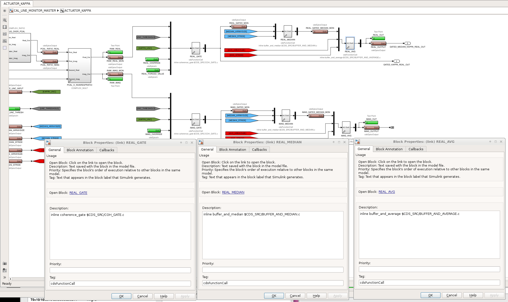
During the prep for install of all the new infrastructure for the O3-level calibration front-end model upgrades at LLO, they discovered another flaw / bug from me. This time, it's a copy-and-paste error with the smoothing process for the time-dependent correction factors.
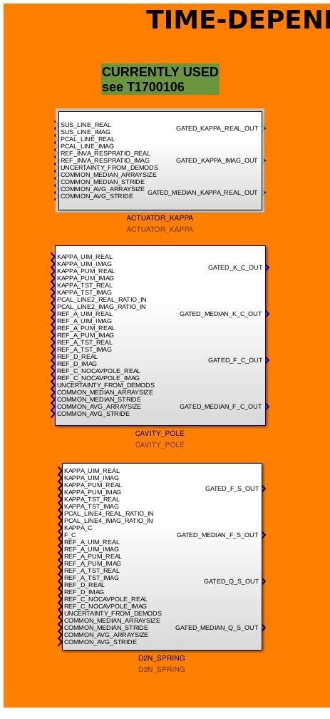
The *design* is to have every raw TDCF, computed in the simulink library
/opt/rtcds/userapps/release/cal/common/models/CAL_LINE_MONITOR_MASTER.mdl
should be fed into three conditioning processes:
(1) a gate function,
/opt/rtcds/userapps/release/cds/common/src/COH_GATE.c
(2) a median function,
/opt/rtcds/userapps/release/cds/common/src/BUFFER_AND_MEDIAN.c
(3) and an average function,
/opt/rtcds/userapps/release/cds/common/src/BUFFER_AND_AVERAGE.c
The way one sets these function calls is by changing the text inside the properties of the block. Like was the problem with the other user-created library parts (see LHO aLOG 46260), these blocks were renamed and -- until today -- the description was hidden, so it was easy for me to miss this copy and paste. Thus, I had mistakenly conditioned each of the TDCFs with Gate, Median, and Median, instead of Gate, Median, and Average.
The library has now been changed, the blocks are now annoted, the h1calcs model compiles successfully, and the above mentioned library part has been committed to the svn in the above descripbed location.
The intent is to install this fix tomorrow. It should not require a DAQ restart.
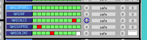
WP8040 New h1calinj model on h1oaf1
Jamie, Dave:
The new model was started this afternoon, it will be added to the DAQ during tomorrow's maintenance.
I have added it to the CDS overview (attached)
Since the calibration group is moving to run individual calibration for the L1, L2, and L3 actuators, in addition to the PCAL lines, we are adding an additional line frequency. The following is a result of suggestions by Evan Goetz in LHO alog 44892, and some other constraints. The LHO lines will become: L1 (UIM) line: 16.7 Hz L2 (PUM) line: 17.3 Hz PCAL line: 17.9 Hz L3 (TST) line: 19.1 Hz PCAL sensing line: 433.7 Note this is slightly different from Evan's proposal after swapping 15.1 Hz and 17.3 Hz between LHO and LLO. For comparison, LLO's is changing to: L1 (UIM) line: 15.1 Hz L2 (PUM) line: 15.7 Hz PCAL line: 16.3 Hz L3 (TST) line: 16.9 Hz PCAL sensing line: 434.9 Hz See LLO alog 42720
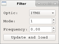
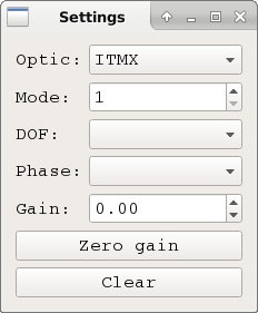
Jenne, Daniel, Jeff K., Sheila, Chris W., Patrick I have created two scripts to aid with violin mode damping: /opt/rtcds/userapps/release/sus/h1/scripts/violin_damping/filter.py This is a GUI to aid in the creation of filter files for damping violin modes. Most notably it scripts the creation of the phase change filters for a given frequency. It is possible the method used here could be made more analytical, if someone has the time to look into how. /opt/rtcds/userapps/release/sus/h1/scripts/violin_damping/settings.py This is a GUI to aid in selecting the DOF, phase, and gain for damping violin modes. Most notably it turns on the correct combination of filter modules for a given phase, assuming that the filter modules are in the banks set by the filter.py script. More details are in the comments at the top of each script. I have also attached a log of the settings I have found to date for each frequency. These still need to be verified.
Double checked that the YAW 4 dither frequency mentioned is set in guardian and is at the center of the bandpass filter. It checks out. Also double checked this for YAW 4, YAW 5, PIT 3, PIT4, and PIT5 dither frequencies.
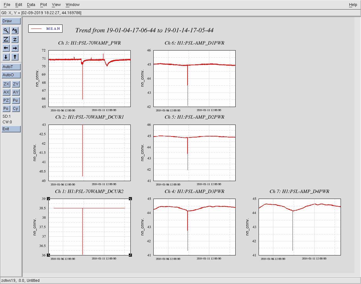
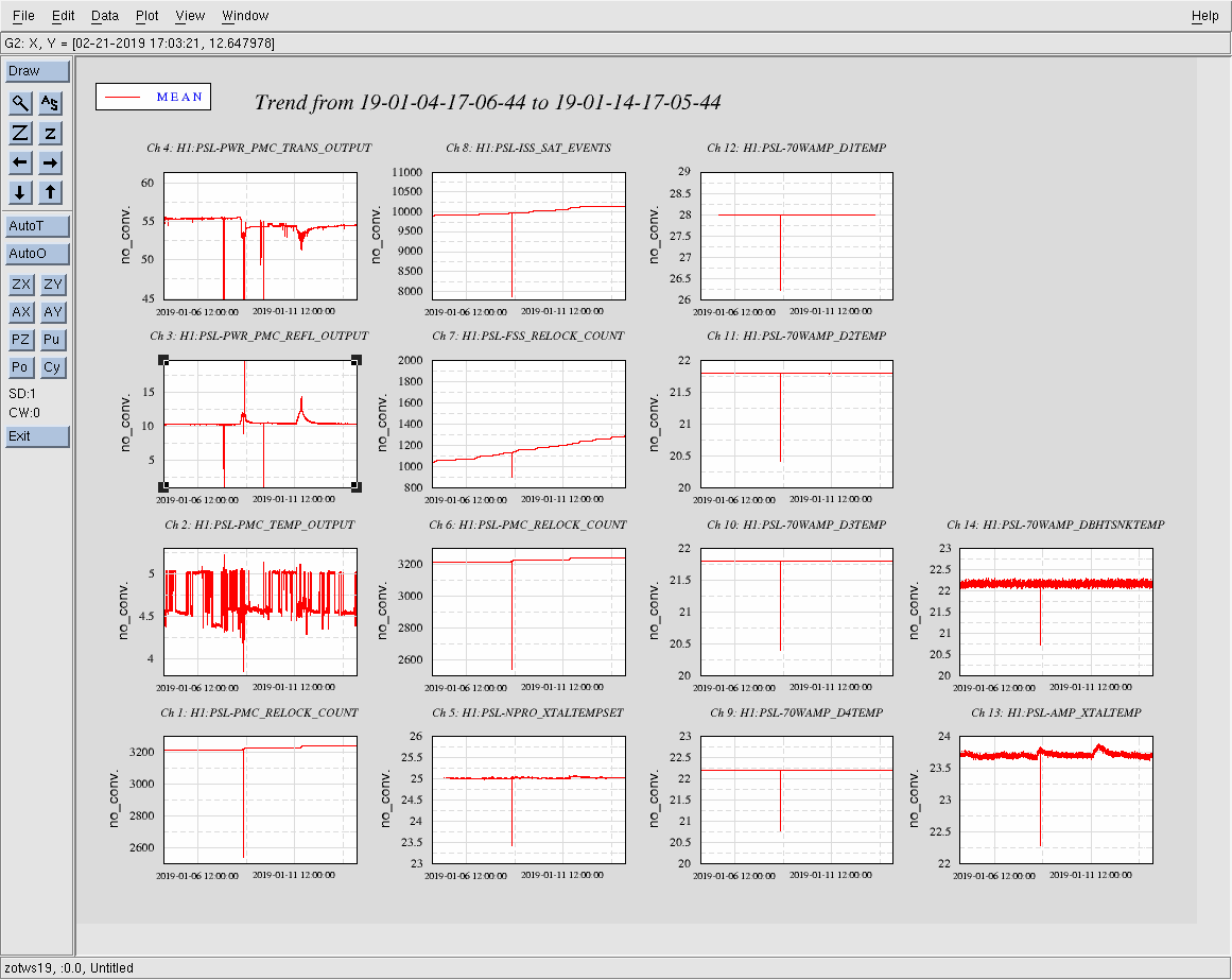
PMC Trans is trending lower over the last week. Perhaps a remote alignment is in order.
For the record.
Addressed TCS Chillers (08:15-08:25 AM PST today)
Note: TJ just informed me the spare chiller (which is staged next to other chillers) now looks like it works, so the plan is to swap it in for TCSy tomorrow during Maintenance.
Laser Status:
Front End Power is 32.22W (should be around 30 W)
70W Output Power is 70.16W
Front End Watch is GREEN
70W Watch is GREEN
PMC:
It has been locked 2 days, 19 hr 40 minutes (should be days/weeks)
Reflected power = 10.32Watts
Transmitted power = 54.45Watts
PowerSum = 64.77Watts.
FSS:
It has been locked for 0 days 0 hr and 10 min (should be days/weeks)
TPD[V] = 2.548V (min 0.9V)
ISS:
The diffracted power is around 2.6%
Last saturation event was 0 days 14 hours and 58 minutes ago (should be days/weeks)
Possible Issues:
TITLE: 01/14 Day Shift: 16:00-00:00 UTC (08:00-16:00 PST), all times posted in UTC
STATE of H1: Commissioning
OUTGOING OPERATOR: None
CURRENT ENVIRONMENT:
Wind: 9mph Gusts, 8mph 5min avg
Primary useism: 0.09 μm/s
Secondary useism: 0.37 μm/s
QUICK SUMMARY:
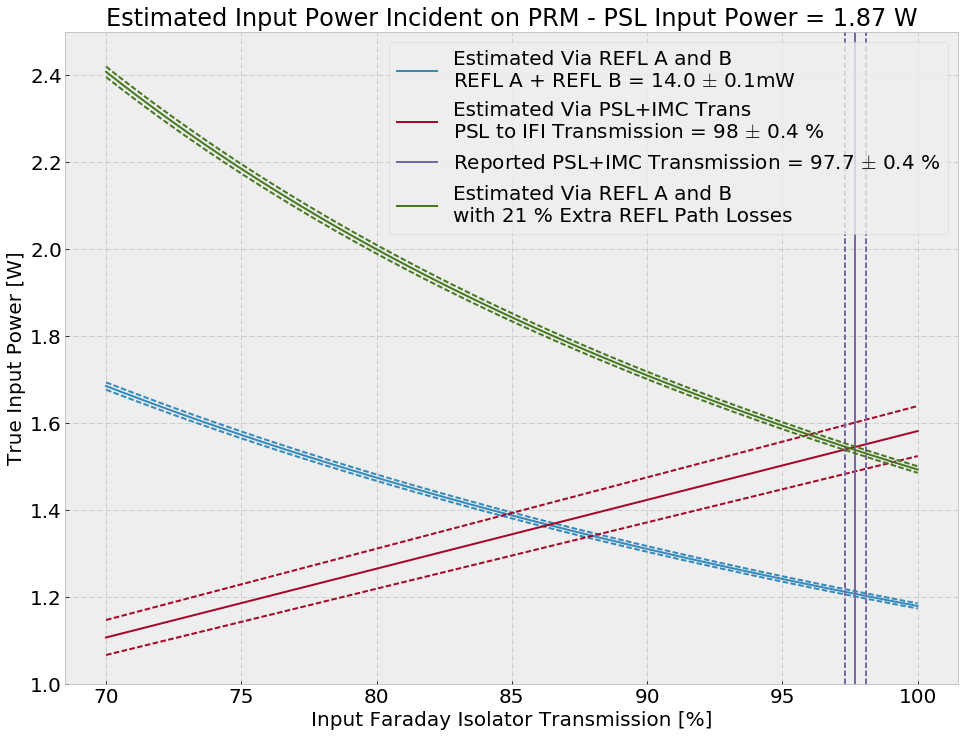
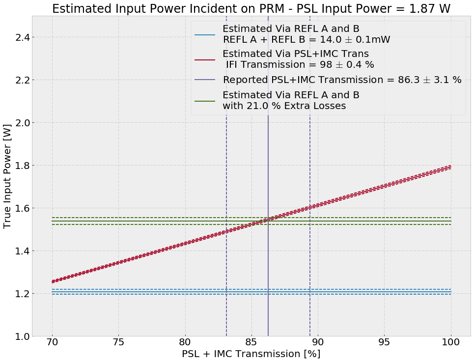
I have been wondering about the true input power, i.e. the input power incident on PRM, ever since the SRCL dither arm power measurement turned out so low.
Conclusion
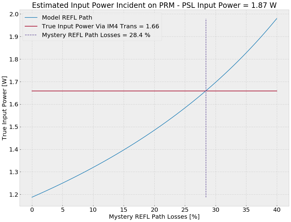
With an input power of 1.87 watts according to the PSL photodiode, we probably have around 1.55 watts incident on PRM, assuming an addition 21% unaccounted losses in the REFL A/B LF PD path.
Power Measurement Methods
I aligned PRM and the input optics, and misaligned the rest of the corner with 1.87 W reported from the PSL input power PD going into the IMC.
IM4 Trans
The easiest way would be to get Pinput would be via IM4 TRANS. IM4 TRANS is calibrated into microwatts, IM4 (aka SM2) transmission is reported to be 2400 +- 200 ppm, and there's what I think is a 90:10 BS (ROM LH1) allowing 10% of the light going to IM4. However, if we turn the crank here we end up with only 0.2 W, which is not possible. This means that IM4 TRANS is not calibrated correctly, or the IM4 transmission path is actually around 8 times less transitive that I though.
REFL A/B LF
We believe that the REFL A/B LF PDs are correct based on the calibrated CARM shot noise. We can use them to calibrate the correct input power. The main issue here is if we use the REFL optical path (4 50:50 beamsplitters, 1 90:10 beamsplitter, one input faraday isolator, and one PRM) and assume no losses, we only get 1.19 W of true input power on the PRM. This could be the case, but it's more likely that there are some unaccounted for losses on the REFL path.
PSL and IMC Transmission
If we trust the old numbers from P1500076 on the PSL and IMC transmission, we can make an estimate of the true input power. We find that by varying the PSL and IMC transmission, we cannot reasonably recover the REFL A/B power levels we see.
PD Powers and Optic Transmissions Assumed
# Most taken from P1500076
# PD calibrated powers
PSL_INPUT = 1.87 # W
REFL_A = 7.3e-3 # W
REFL_B = 6.72e-3 # W
IM4_TRANS = 50.24e-6 # W
# PD uncertainties
dREFL_A = 0.04e-3
dREFL_B = 0.03e-3
dREFL_SUM = np.sqrt(dREFL_A**2 + dREFL_B**2)
# Transmissions
T50 = 0.5
T10 = 0.1
T_PSL = 0.953 # +- 0.013 PSL to MC1 transmission
T_IFI = 0.977 # +- 0.004 https://dcc.ligo.org/DocDB/0119/P1500076/003/Mueller16rsi-AdvIO3.pdf
T_IMC = 0.92 # +- 0.031
IMC_ModeMatching = 0.984 # 0.001
T_PSL_to_IFI = T_PSL * T_IMC * IMC_ModeMatching
T_IM4 = 2400e-6 # +- 200e-6 E070092
T_PRM = 0.031 #
# Trans Uncertainties
dT50 = 0.01
dT10 = 0.01
dT_PSL = 0.013
dT_IFI = 0.004
dT_IMC = 0.031
dIMC_ModeMatching = 0.001
dT_PSL_to_IFI = np.sqrt( T_PSL_to_IFI**2 * ((dT_PSL/T_PSL)**2 + (dT_IMC/T_IMC)**2 + (dIMC_ModeMatching/IMC_ModeMatching)**2) )
dT_IM4 = 200e-6
This calibration is now implemented in H1:IMC-IM4_TRANS_{SUM,PIT,YAW} FM10.
The IM4_TRANS is no longer calibrated in µW due to a gain change in the whitening. The calibration dates back to alog 9716, where the whitening gain was 36dB. It is 18dB now, so the "µW"-readbacks are 18dB too low.
We added NSUM channels to the IM4 and MC2 Trans QPDs to facilitate an additional calibration of the incident power onto these mirrors.
With this additional 18 dB of whitening gain, we can calibrate true power input the simple way using IM4 TRANS:
Requested Laser Power = 2 W
PSL Reported Power = 1.87 W
T_IM4 = 2400 ppm
True Input Power = 1.66 W
If we let T_IFI = 0.977, T_PSL = 0.953 and IMC_ModeMatching = 0.984, then T_IMC = 0.968.
And the mystery REFL path losses are 28.4% (see attachment).
I know Gabriele is looking at how these compare H1 vs. L1, but just a preview of how much HAM1 motion is affecting our ASC signals...
I've taken the times that Sheila posted above, and gotten the transfer functions from the tabletop L4Cs to the different ASC degree of freedom control points (they are saved at a faster rate than the error points, although the error points are easier to calibrate). Then projected the quiet non-injection tabletop motion onto each degree of freedom.
Attached are 6 plots, looking at the DC centering loops and the WFS (CHARD and INP1), for the 3 different injection directions. The WFS themselves don't really see much with the table motion, but the DC centering loops in pitch are seeing a lot of this table motion. This is in contrast to LLO, who needs to use the tabletop L4Cs to feedforward to CHARD. None of the table motion is affecting the centering loops above about 20Hz. The L4C projections are only displayed in the plots if there is anywhere in the transfer function that has coherence during the injection above 0.7.
The ability to feedforward the L4C signals to the ASC has not yet been implemented, since without that data it wasn't clear which DoFs needed it the most. LLO hard-codes the ability to feedforward to CHARD only, which we don't want to do since that's not a degree of freedom that is bothered by the table motion. Note however that the sender parts are now in the SEI model, so if we decide to implement feedforward, it will only require an ASC restart, not any SEI restarts.
Since the injections are not strong enough to be seen in DARM, all we can do is compute upper limits, as shown below.