On Chandra's request, the beam tube vacuum alarms upper level have been restored to 5.0e-09Torr from their temporary level of 2.0e-08Torr following MX ion pump work. The alarm system was restarted.
<Channel name="H0:VAC-MX_X1_PT343B_PRESS_TORR" low="1.0e-10" high="5.0e-09" description="VE gauge, MX X1-beamtube, CC">
<Channel name="H0:VAC-MX_X5_PT346B_PRESS_TORR" low="1.0e-10" high="5.0e-09" description="VE gauge, MX X2-beamtube, CC">
Noticed frozen cameras on the wall this morning for:
Symptoms: Camera views on video5 wall computer were froze for these cameras (including time stamp froze), and also could not bring up camera via the "!Launch fixed" button via medm.
Carlos was able to bring back PR3 by performing an individual start on h1digivideo1. But ITMy & ETMy on h1digivideo2 were not as trivial, with ITMy remaining dead. Tried individual starts, killed processes, and also performed a full restart on the server h1digivideo2. Even with issues continuing, the h1digivideo2 web interface thinks they are all Running.
ETMy is sort of back, but it is slow (updates every ~15sec vs 1sec); even after I tried a Stop/Start via the Monit web interface. Will leave on wall.
ITMy remains dead, and will require further work (Carlos and Richard mentioned this particular camera is known for causing grief). Will take this camera off the wall in the meantime & file an FRS.
Please ignore alarms from alarm handler at operator console for PT427 (Y2-8 gauge at IP17 which is 250 m from EY station). Gauge is off again likely due to lack of solar power.
I didn't alog this at the time but the SEIPROC, HAM-ISI and BSC-ISI models were updated this week to allow us to select which ground sensor we want to use, as well as updates to the sensor correction paths. The HAM-ISIs now have code (that the BSCs have had for a while) to smoothly ramp between different sensor correction paths, and a few other changes. We also added a sensing matrix and some extra sensor correction paths to retain the use of cross DOF sensor correction (i.e the Z to X/Y sensor correction like I added on HAM3&4).
This update also added the ability for all of the ISI's to use the common mode subtracted ground sensor correction paths, that the seismic group has been trying to develop to help with earthquakes. The idea is that by subtracting the calculated common mode motion of the entire site, we can improve the isolation and reduce drives by only isolating against the local differential ground motion. In the SEICONF guardian, the EARTHQUAKE state is now using that where it's available, although, this code has not been added to HEPI, yet.
Next week I would like to do one more round of model updates. In SEIPROC, I want to clean up the ground signals to be simpler and reflect the fact that we SEIPROC is written to digest CS BRS (which we don't have, but LLO may want to copy this model, I don't know what they have for an equivalent model). This means there are NORM paths (the normal paths, meant to be a low tilt sensor) and the UNCOR paths, which would be a path that bypasses any BRS as a fall back. This only involves changing PCIE parts from SEIPROC to CS chambers at the top levels of the models and shouldn't affect any control paths. I've done the makes for all the chambers, everyone compiles.
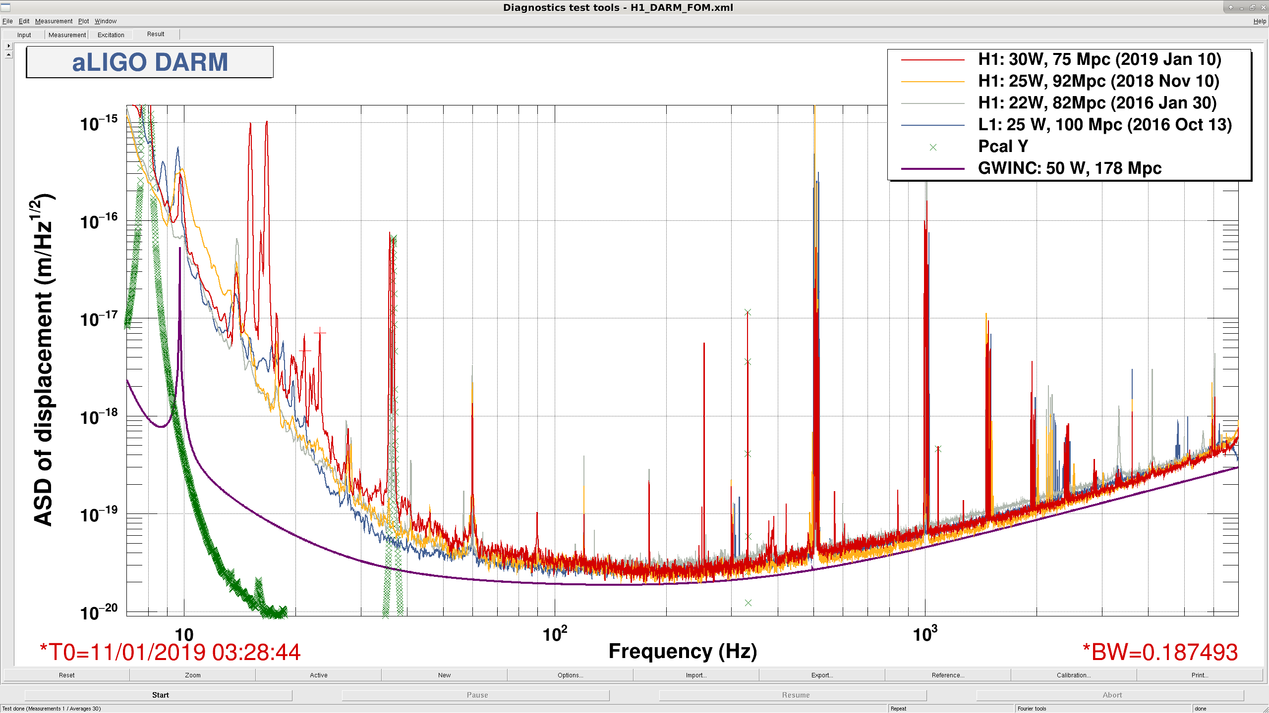
- Locked for four and a half hours during Daniel dinner, lost lock due to small earthquake right as I returned. - Lockloss right after ENGAGE_SOFT_LOOPS. -- On second lock, stepped through the state, had trouble with CHARD P/Y ringing up when engaging FM1 (+30dB). Caught by disengaging FM1s and instead increasing CHARD P gain from 2 to 20 and CHARD Y gain from 2.5 to 25. Had to reduce both gains to 15 to get arms to settle. -- Lost lock when switching on SRC1 P/Y FM1s (-20 dB) and ramping SRC2 P/Y gains from 100 to 15 causing a 0.6 Hz ringup. Seem like a CHARD/DHARD Pitch ringup triggers by lowered SRC gains. -- Next time was able to proceed through ENGAGE_SOFT_LOOPS by hand with no problems. Not clear what was different between these two locks. - Got to NOMINAL_LOW_NOISE for about 15 minutes. The lock was particularly ratty, POP18 and PRG were oscillating periodically at about 0.5 Hz, and the IX EX saturation audio alarms kept sounding. Seems to have been an oscillation in the pitch loops, CSOFT and SRC1 look most guilty. - Lost lock stepping through ENGAGE_SOFT_LOOPS on CHARD P/Y again. -------------------------------------------------------------------------------------------------------------------------------------------------------------------------------------------------------------------------------- FOM is from 4 hour lock earlier. Calibration is a by-hand matching of the PCAL lines to DARM. Scattering seems to have been reduced from what we've seen last week.
That 4 hour lock: - 30 W requested input power - DARM actuation entirely on L1, L2, and L3 ETMX
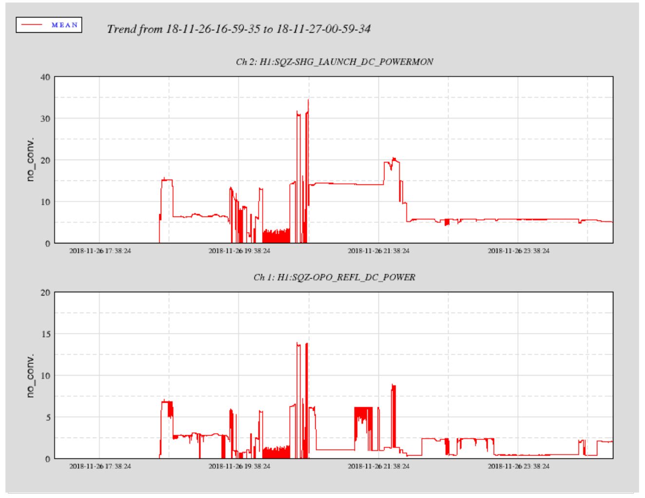
The green fiber power drop posted in 45903 happened 7 days after the chamber was pumped down (VacGnPwr.pdf attached). This low resolution spot also shows a large spike in the green power fluctuations. This was before we managed to stabilize the green power (by tweaking the laser mode, polarization through the EOM and adding a noise eater).
GnSpike.pdf (attached) shows a higher resolution plot of this power spike to confirm the maximum height and duration. After this power spike we are still able to achieve ~50% throughput from launch power to refl diode although it is sporadic and quite unstable.
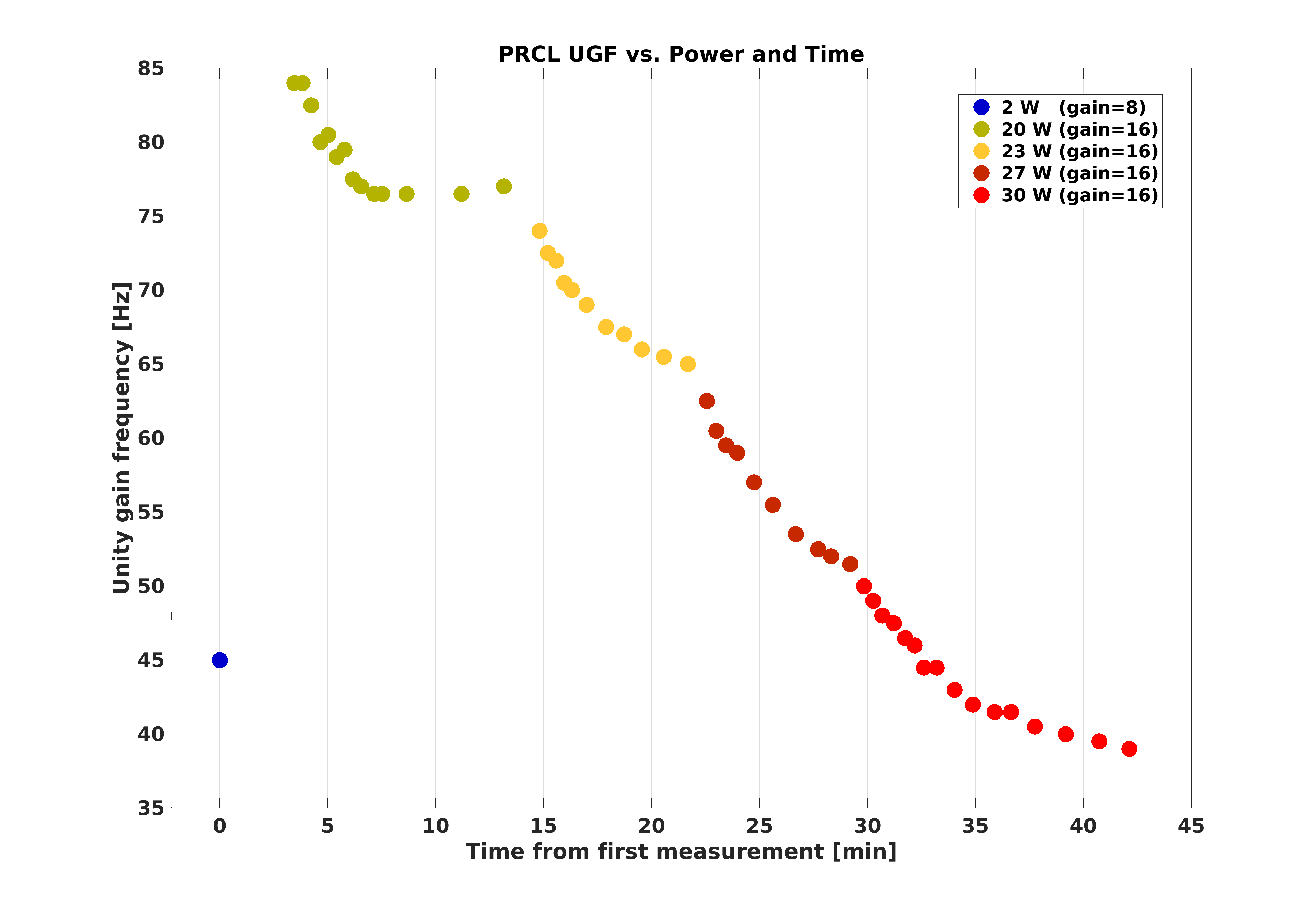
During one of our powerups today, I measured the PRCL gain several (52) times. The goal is to see if we really need the big lookup table of nested IF statements in the increase power guardian states that currently changes the PRCL digital gain (or even more complicated, a UGF servo), or can we simplify the PRCL gain setting as we power up.
The problem is that the UGF drops as the interferometer thermalizes at higher powers. The nested IF statements are trying to keep the PRCL UGF always roughly constant. But, the phase bubble of the PRCL loop is pretty generous, so we can handle a fair amount of gain drift. The edges of the phase bubble are at 13 degrees and 121 degrees, so as long as we don't get close to either of those values, we should be fine.
Attached is the PRCL UGF plotted versus time since my first measurement at 2W. The colors of the dots indicate what PSL injected power we were using at that time, as labeled in the legend. The legend also shows what digital gain was in the PRCL servo at that time. At 2W it is half the value of the higher power values. But, note that all the 20W+ measurements have a constant digital gain, while the UGF is dropping by about a factor of 2. The highest UGF when we first arrive at 20W is 84 Hz, with a phase margin of 23 degrees. The lowest UGF here is 39 Hz with a phase margin of 35 degrees.
The peak of the phase bubble is at about 45 Hz, so that's where we want the UGF to end up when we're done. Right now, the state LOWNOISE_LENGTH_CONTROL sets the digital gain down to 11 from 16, so I think it probably has been setting the final nominal low noise PRCL UGF to be 27 Hz, which has a phase margin of about 28 degrees. This value of 11 for the digital gain was set in Oct 2018, when we were using 20W PSL power. So, with the new 30W of PSL power, I am changing the value in the guardian to be 16, where all of my measurements are.
My conclusion here is that we can go to 20W, set the PRCL gain to be 16 (which puts the UGF at the high side of the phase bubble), and then just leave it and it will relax to a final of 38 or 39 Hz. Then, in LownoiseLengthControl we can set the gain to be a bit higher to bump the UGF back to 45Hz. Anyone is welcome to do this, and remove the nested IF statementss from the powerup states, and put the higher value into LownoiseLengthControl, but I don't want to do something so big minutes before I walk out the door.....
T Vo, Sheila
On the next lock acquisition we edited the POWER_30W state to remove the changes in PRCL digital gain, it is set to 16 in LOW_NOISE_LENGTH_CONTROL. This seems OK.
When requesting PRMI_LOCKED or DRMI_LOCKED out of CHECK_MICH_FRINGES the guardian used to not set the MICH gain correctly.
We fixed that by first requesting PREP_DRMI in both states to make sure the DRMI guardian sets the gains again.
E. Goetz, J. Kissel Continuing progress after yesterday's win in producing time-dependent correction factors LHO aLOG 46328, today I tackled item (1): Evan, Lilli, and Shivaraj have put in a lot of good work exposing and fixing residual problems with the python suite of code now used to create the DARM model ("pyDARM") when it comes to getting signs right; see G1900019. As such we now believe we have it all right. Thus, I've now - updated the pyDARM suite, /ligo/svncommon/CalSVN/aligocalibration/trunk/Common/pyDARM/src/ actuation.py sensing.py computeDARM.py - regenerated and installed the epics records that report the DARM loop model at the calibration line frequencies for use in calculation the time dependent correction factors, using zotws10:/ligo/svncommon/CalSVN/aligocalibration/trunk/Runs/O3/H1/Scripts/CALCS_FE$ python3.5 createEPICS_for_20181205.py -w The only changes are in signs -- no magnitude change (see item (3) below). The magnitudes remain the same as they were for ER13. The record of these new results can be found in /ligo/svncommon/CalSVN/aligocalibration/trunk/Runs/O3/H1/Results/CALCS_FE epicsrecords_model-H1_20181205_created-20190110.txt for use elsewhere. Still to do: (2) The gating system (which smoothes out the TDCF for application to DELTAL_EXTERNAL) and override system (which allows us to bypass non-functional parts) don't yet have all settings turned ON in such a way that the relative actuator strength changes -- a.k.a. kappa_UIM, kappa_PUM, and kappa_TST -- are spitting out live values. In this brief moment in time where the optical plant parameters were working, all of the actuator kappas were bypassed and spitting out +1.0. (3) As mentioned above we're still using a pre-ER13 measurement to determine the DARM loop reference model, which in turn determines the EPICs records, which determine the calculated TDCFs. The actuator measurements were quick and dirty. The IFO was still at 20 watts. Thus -- when I see that the corrective gains, the kappas for both actuator and optical plant, have magnitudes at the 10-30% level, I'm not yet sad. Now that we're electing to stick at 30W input for a while, while we hunt for noise, we should re-take -- or in some cases take for the first time -- quality measurements that will get the system to levels needed for ER14 / O3.
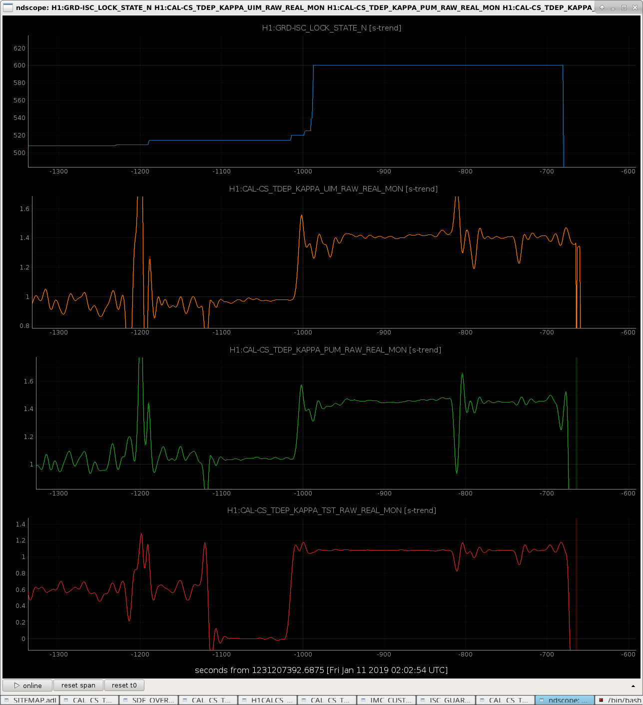
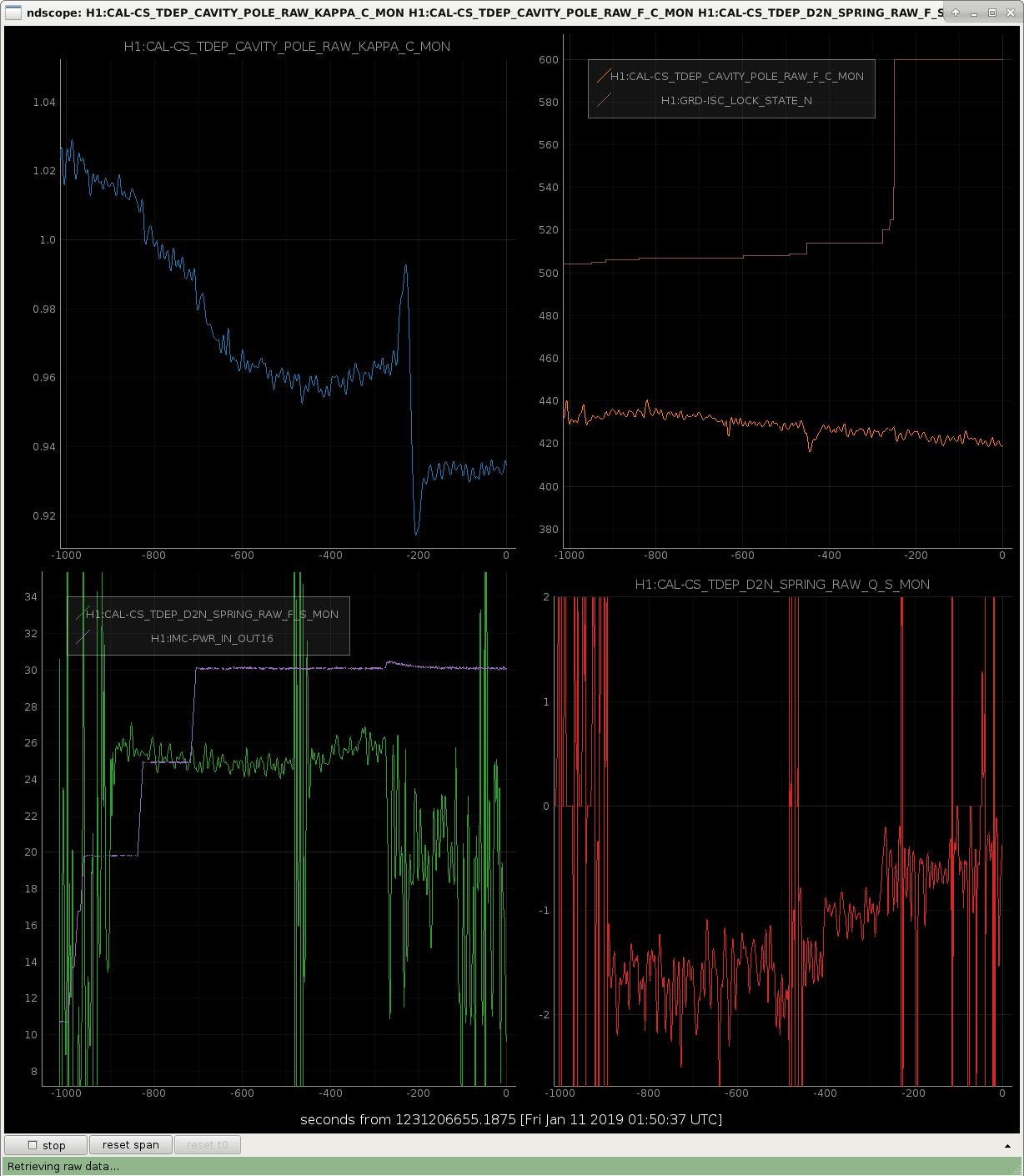
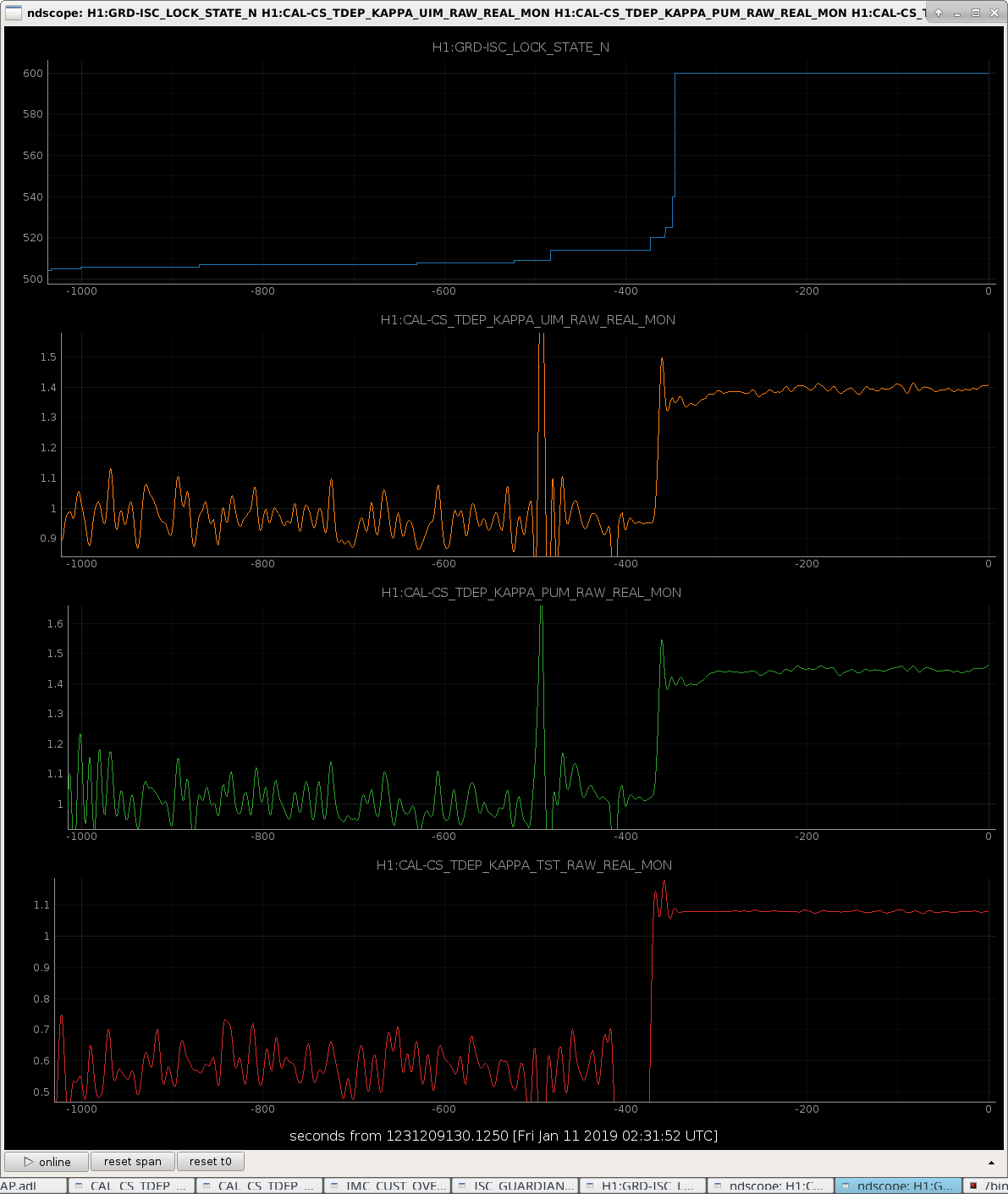
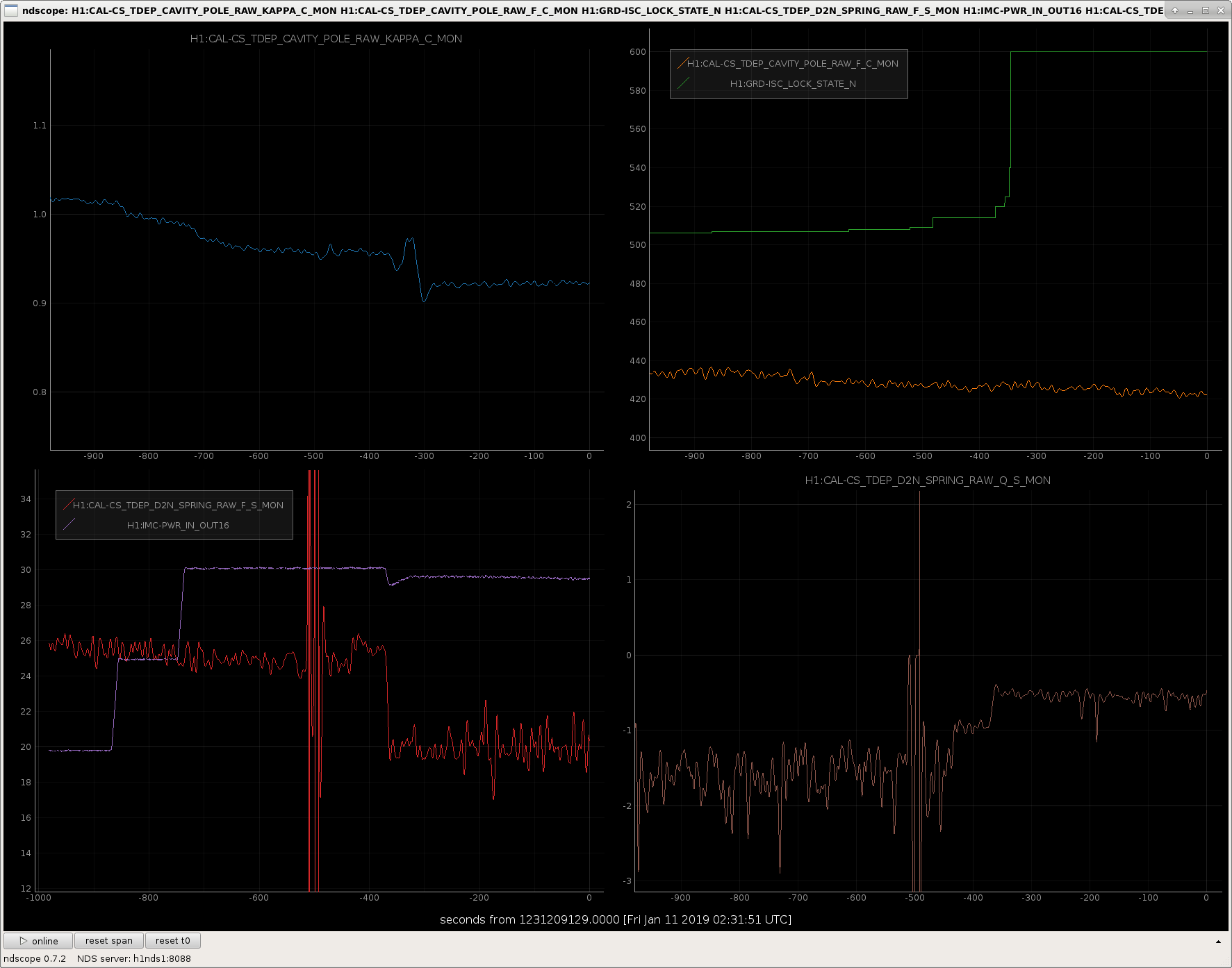
A sneak peak at the interferometer power up from 2 to 30 W and the transition from some ETMY DARM control to full ETMX.
Comments:
- The signs of all TDCFs are right!
- The calibration lines are loud enough that one starts to get sensible signals by the time we're in DC readout.
- There're some kicks to the system when we pass through switching to low noise coil drivers, when we transition EY to EX, and ... something when we land in nominal low noise. To be determined, and hopefully fixed.
- The change of the kappa_UIM and kappa_PUM from close to 1.0 to 1.4ish happens exactly when UIM and PUM control transition from EX to EY. Probably right. I can easily believe that the UIM and PUM between stages are 40% different (or there's just some gain that shouldn't be there in the replica actuator path... CRAIG...).
- The relative optical gain (kappa_C) passes through 1.0 right around when we're at 20 W -- which is what the reference model is tuned for, and then gets stable at 90% once we're at 30W. Also makes sense!
- Cavity pole frequency remains pretty stable throughout the power up, only a ~10 Hz drop. Not bad! Twas on a downward trend though.
- Lots of things to work out when it comes to divide-by-zero problems in the optical spring parameters...
If you like these ndscope templates, they live here:
/ligo/home/jeffrey.kissel/Templates/NDScope/
CAL_tdcfs_actuatorplant.yml
CAL_tdcfs_opticalplant.yml
And we managed to get another lock stretch that we're leaving alone. Start time 2019-01-11 02:26 UTC
Ran through initial alignment in the morning. Could not get ALS DIFF to lock until Stefan found the setting that was out of nominal (alog 46335). 15:39 UTC Chris to mid X to retrieve tools 15:44 UTC Brian with Apollo through gate 16:18 UTC Peter to optics lab 19:34 UTC Peter back 20:18 UTC Robert to end X to switch ESD channel on voltage monitor 20:53 UTC Brian with Apollo through gate
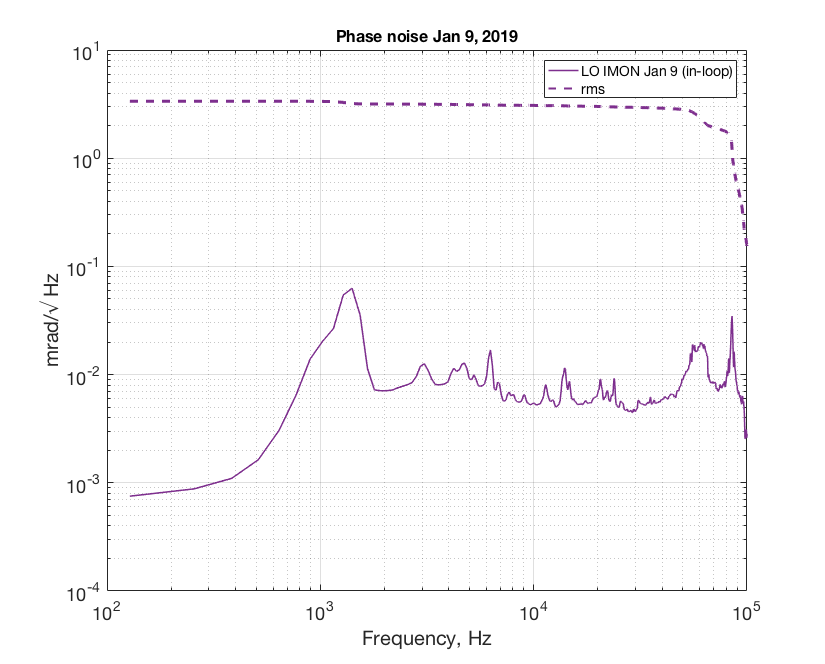
After injecting some squeezing in the IFO and saw nothing we thought it's a good idea to go back to the HD and measure squeezing with PSL LO. Sadly due to another 30% pump transmission drop (alog46290) the max non linear gain we could get is 2. The phase noise measured from LO error signal (in loop) suggested 3 mrad. Fringe visibility was 98.5% (I used 98% for the model below).

The measured loss in the path can be found in Haocun's github here. The calculated total efficiency is 0.8147. This measurement suggested we have extra loss up to ~20% that was unaccounted for.
The first measurement Haocun took after the vent can be found here (we locked LO with Mephisto LO at the time). We still had intensity noise issue at the time so the data points were all over the place because the nlg was unstable. I'm not sure if the extra loss has always been there or degraded over time after the vent.
We could not have measured ~4.5 dB of squeezing in 45586 with losses as high as in this recent measurement. We can be confident that we understood our losses in the homodyne path in November, regardless of the fluctuating green power and nonlinear gain.
This afternoon Nutsinee went to the table to look at the seed power transmitted, we can compare this to earlier measurements of the seed power to check for changes in the losses inside the chamber that is independent of the homodyne path losses.
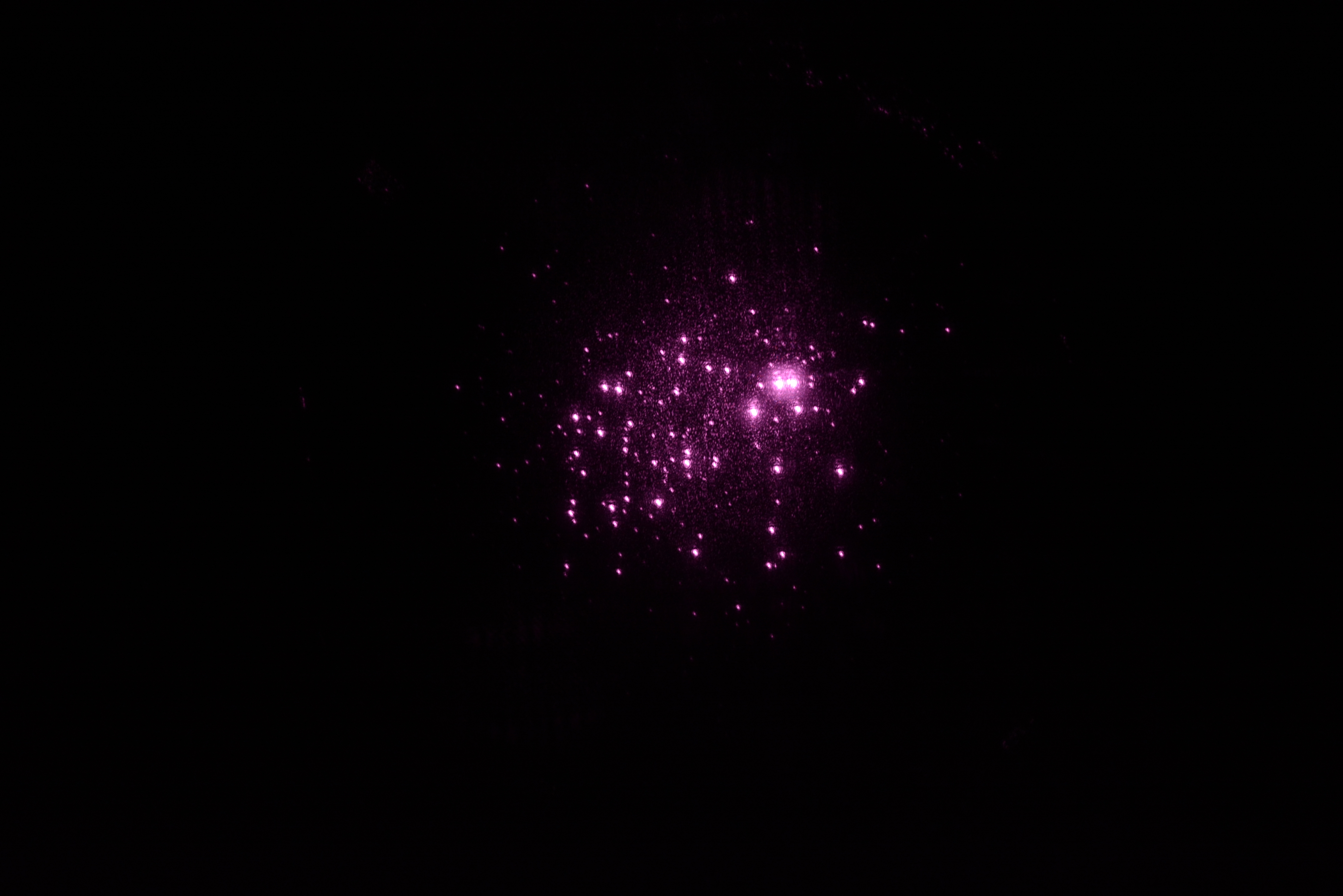
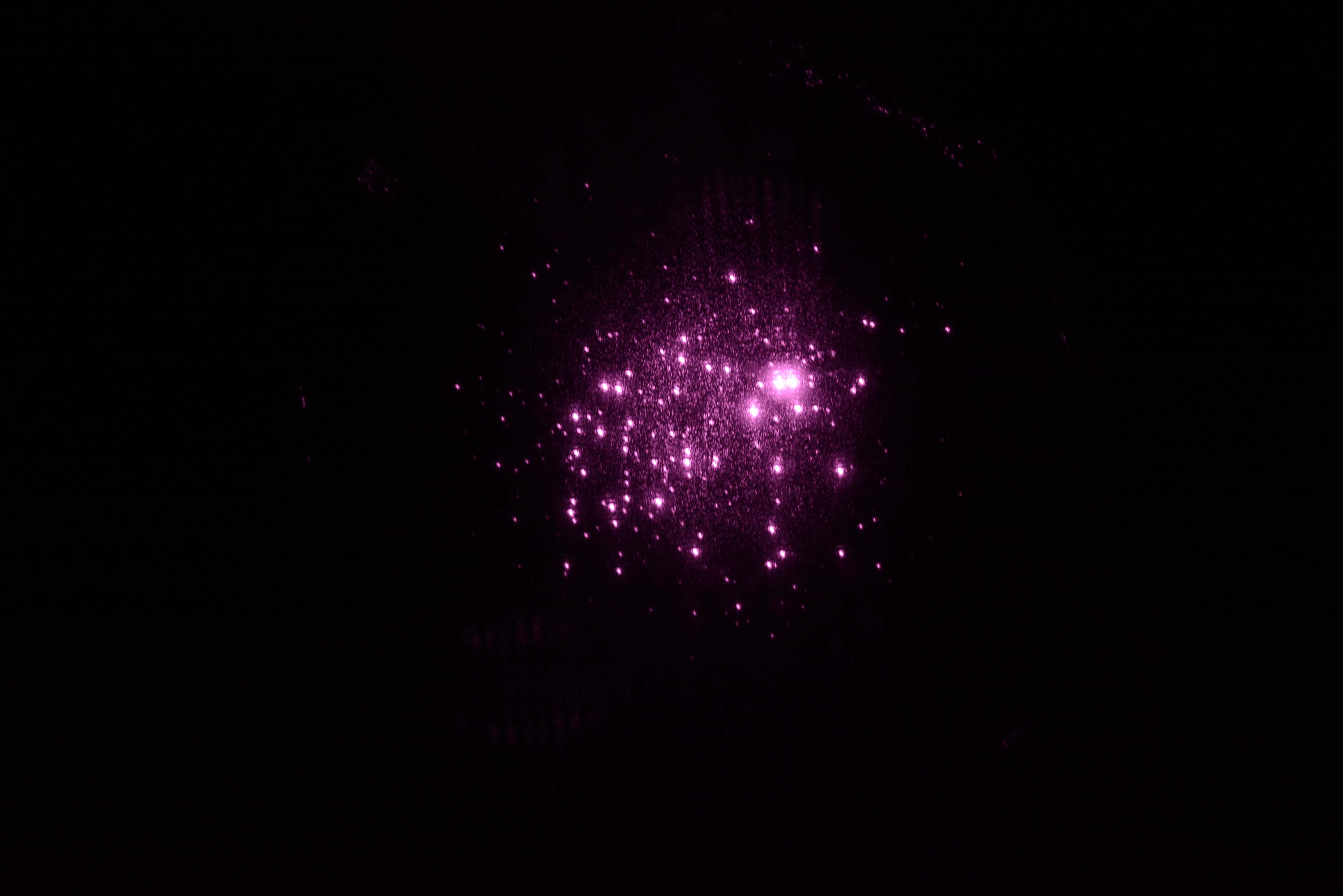
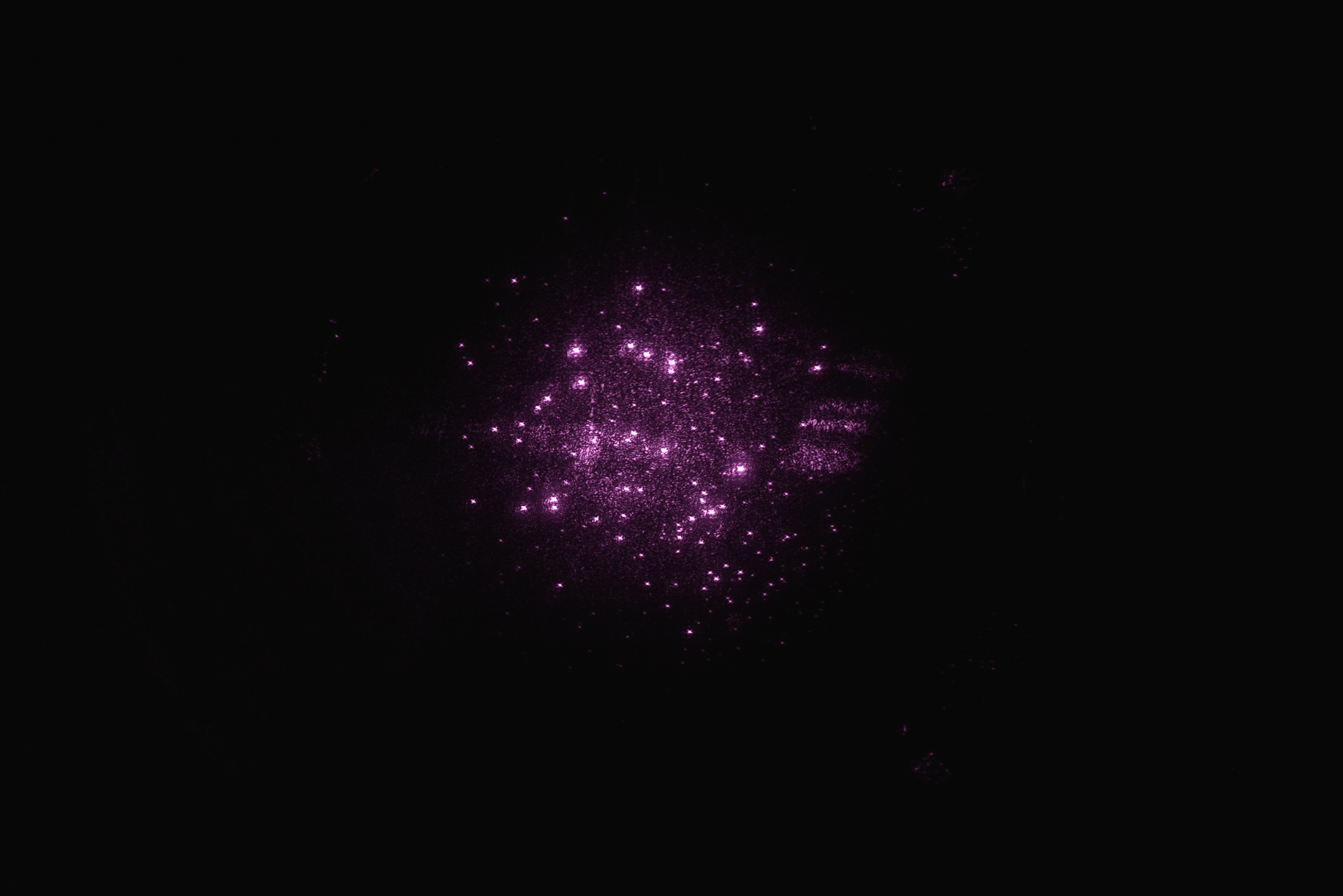
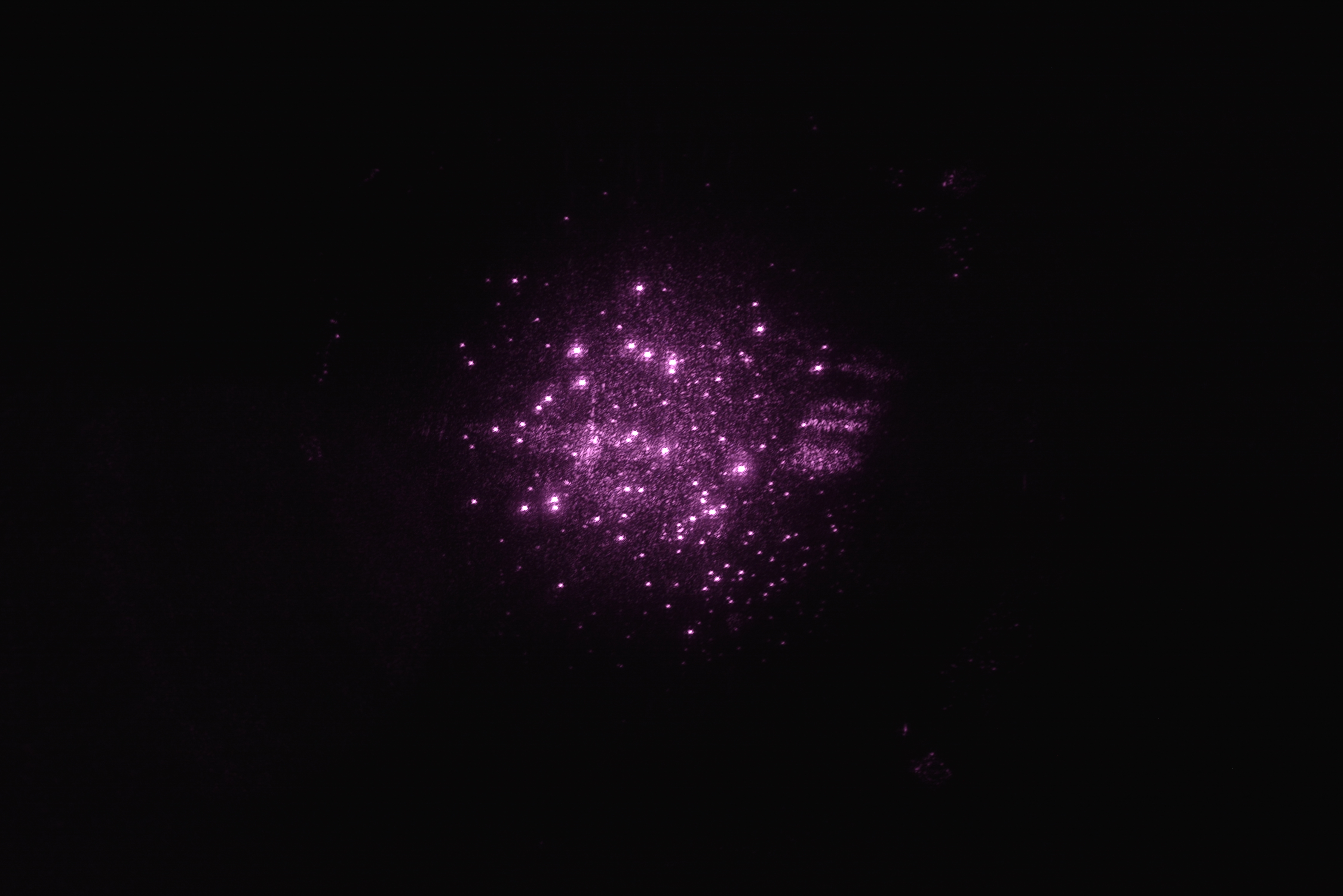
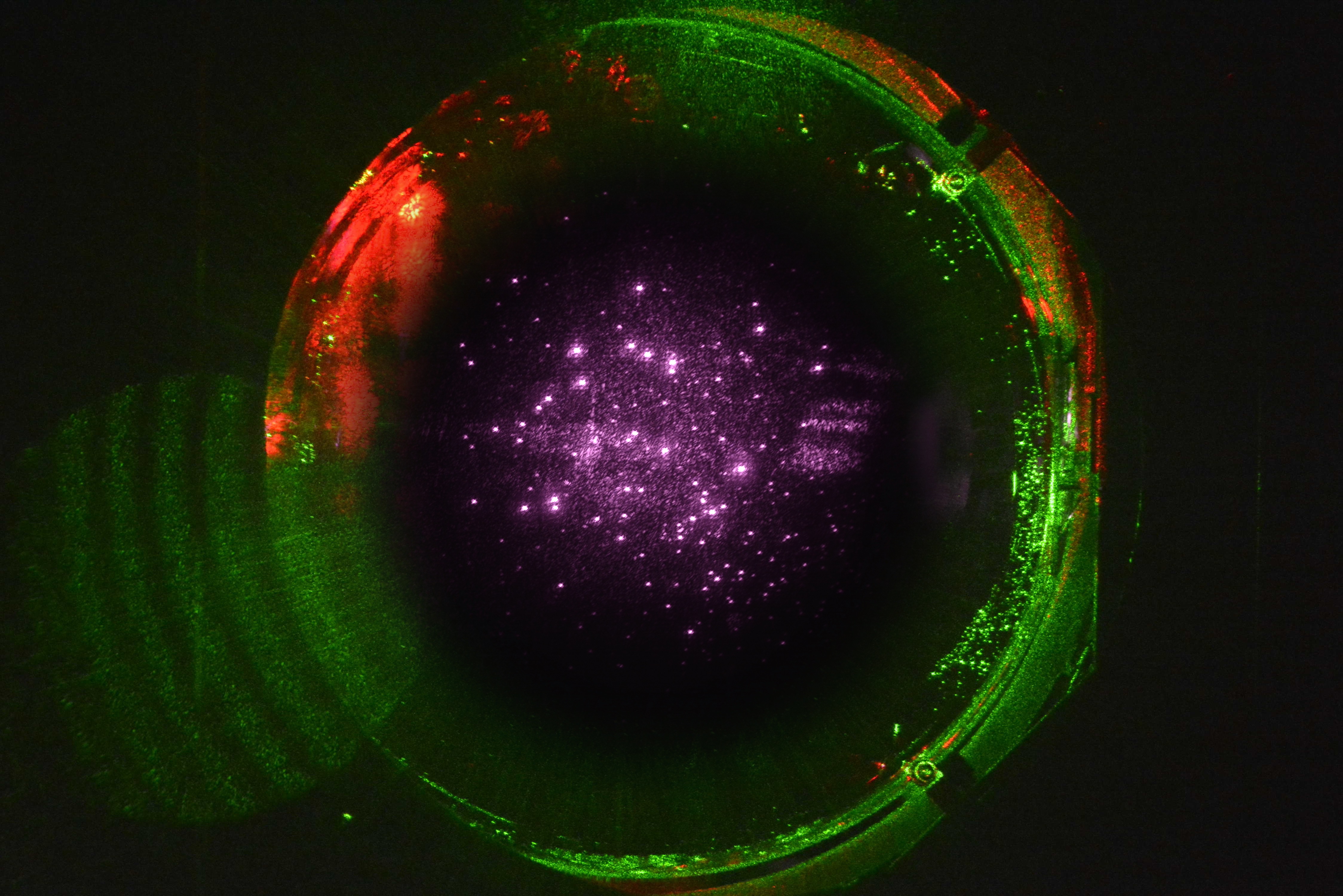
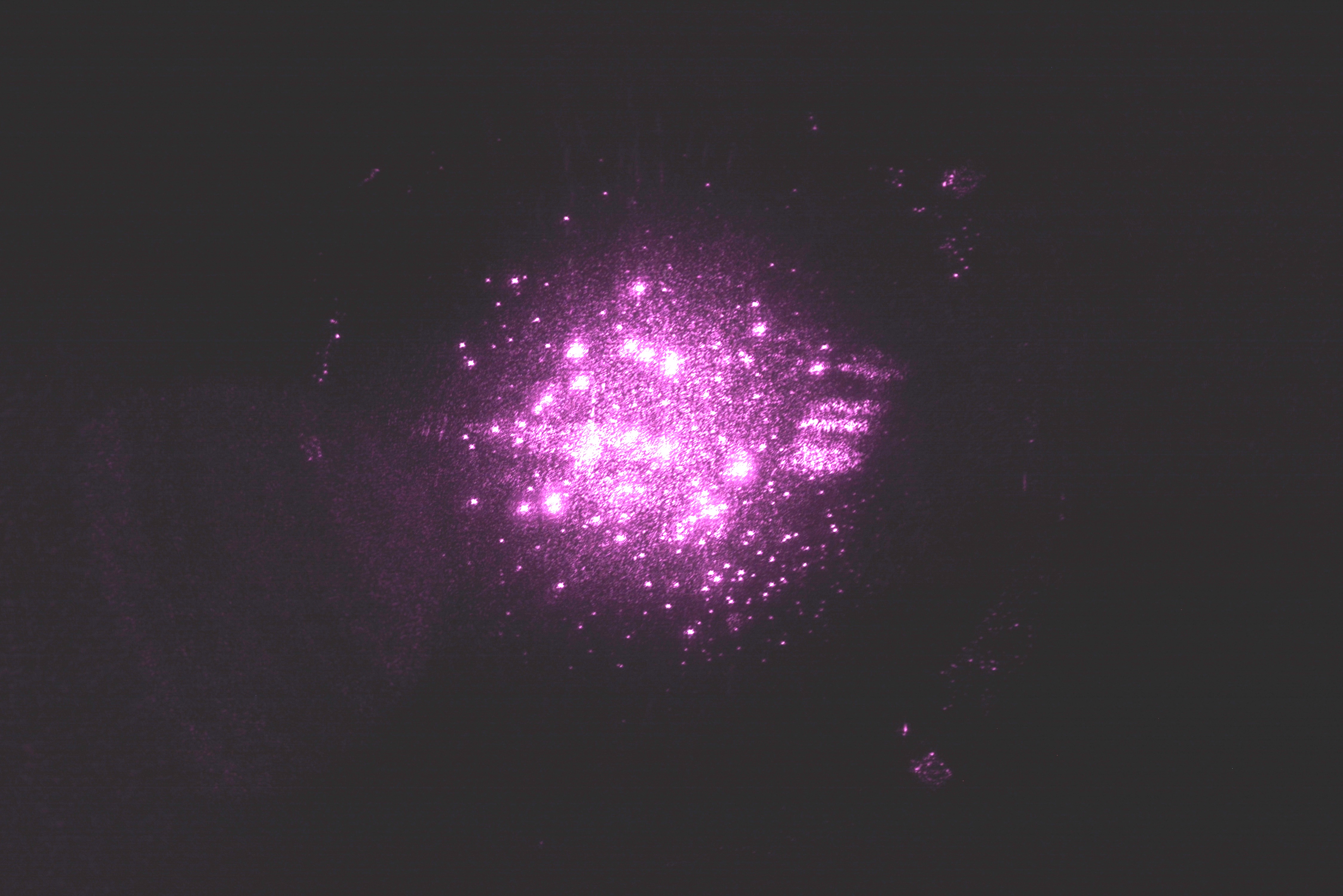
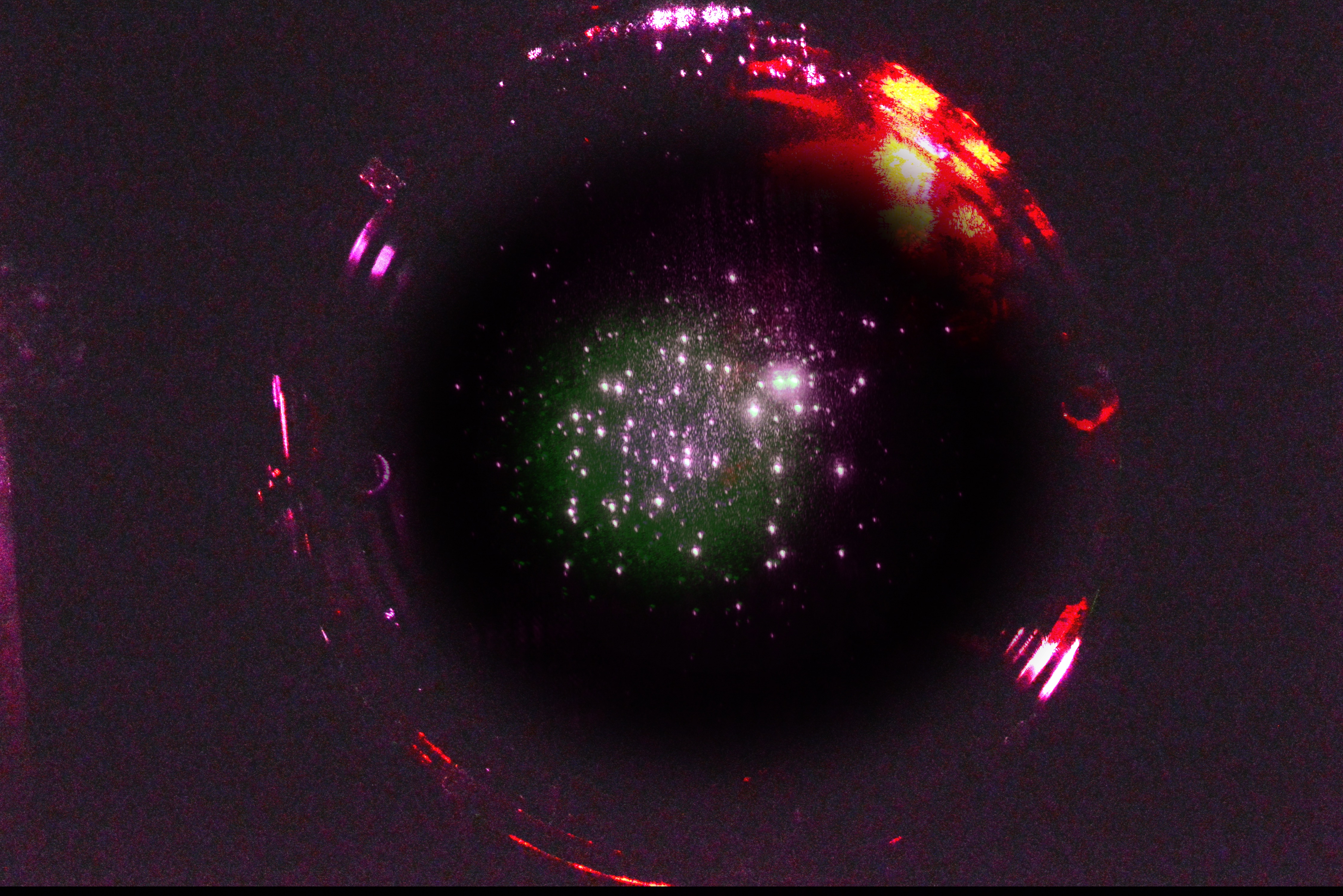
Attached below are images of the HR surfaces of the H1 ITMs with IR light resonating in the arms (19.7 W of 1064 nm laser light).
They were captured by Jeff Bartlett a few weeks ago using the "Pcal" ITM camera systems mounted on the spools at the ends of the beam tube manifolds in the LVEA, near the cryopumps.
The camera settings were:
ITM-X
#109 ISO 800, shutter 1/800
#110 ISO 800, shutter 1/400
ITM-Y
#016 ISO 400, shutter 1/500
#110 ISO 250, shutter 1/200
The assembly drawing for the camera system is LIGO-D1500073-v9.
Kentaro Mogushi's technical note regarding camera system upgrades to minimize aberrations introduced by the vacuum windows is LIGO-T1700540-v3.
Note that these are the first IR images after implementing Kentaro's upgrades. Image quality may improve slightly as the systems are adjusted.
Gabriele and I were curious as to the exact locations of the spots on these images. I played with the brightness and contrast of ITMY until I could see some fiducials of the cage structure (in this case, the EQ stops on the right hand side of the image - see first attached image). Then, I super-imposed this on an old image of ITMY from aLOG 42520 that showed the cage structure much more clearly. The results are attached:

The camera position is fixed (physically locked down), the suspension cage is also fixed, and the position of the heads of the EQ stops are well known. By using the EQ screw heads as the zero position, the location of spots on the optic face can identified. I made a conscious decision in these frames to turn down the exposure to accent the surface spots. In most the position of the EQ screw heads are visible.
Here's ITMX blended with images from aLOG 43174 and aLOG 42774

Mark D., Tyler G., Chris S., Gerardo M., Kyle R.
Gerardo M. and I leak tested the new CFF joints after the installation was done this morning and measured a 1.7 x 10⁻⁸ torr*L/sec helium leak at the Gate valve to chevron baffle spool joint -> This joint is visibly "gappy" for a portion of its periphery even after subsequent re-torques -> looks like the gasket may have been out-of-round -> I shut down the pumps and leak detector but left everything in place. We will redo this joint during the Aug. 28th maintenance period.
NOTE - We will need to soft-close GV5 and GV7 and, thus, interrupt the IFO during the Aug. 28th maintenance day. We will also need the South Crane for a few hours and will need to coordinate with the people who will be on site doing the annual crane inspection during that day.
Yes, ASSY-D1600431-003.
FRS Ticket #12123 filed.