Sheila let me know that they had some trouble last night with reducing the RF45 modulation depth at 2W. Things like PR gain became noisy, and POP90 increases, but things got better as they powered up.
The reason, back in fall 2016, that we had been doing RF45 before increasing power is that we had (at that time) been going straight to 50W in the IncreasePower state, and we saturated the AS WFS (alog 29750, bullet point 3) once at 50W. Also, the AS port trigger PD that is used for the fast shutter was close to saturation (alog 28909).
So, now that we have split out going to 20W versus going to higher powers (right now 30W), we can move the 45MHz modulation depth reduction in between.
I have done this, but since the state numbers were only 1 apart, to make the order correct on the states "ladder" screen, I have swapped numbers 504 and 505. State number 504 was the RF45 reduction, and state 505 was IncreasePower. Now, 504 is IncreasePower and 505 is reduce_rf45_modulation_depth.
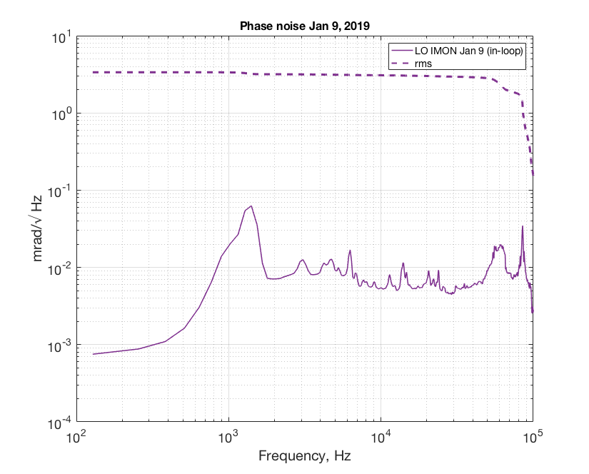
After injecting some squeezing in the IFO and saw nothing we thought it's a good idea to go back to the HD and measure squeezing with PSL LO. Sadly due to another 30% pump transmission drop (alog46290) the max non linear gain we could get is 2. The phase noise measured from LO error signal (in loop) suggested 3 mrad. Fringe visibility was 98.5% (I used 98% for the model below).

The measured loss in the path can be found in Haocun's github here. The calculated total efficiency is 0.8147. This measurement suggested we have extra loss up to ~20% that was unaccounted for.
The first measurement Haocun took after the vent can be found here (we locked LO with Mephisto LO at the time). We still had intensity noise issue at the time so the data points were all over the place because the nlg was unstable. I'm not sure if the extra loss has always been there or degraded over time after the vent.
We could not have measured ~4.5 dB of squeezing in 45586 with losses as high as in this recent measurement. We can be confident that we understood our losses in the homodyne path in November, regardless of the fluctuating green power and nonlinear gain.
This afternoon Nutsinee went to the table to look at the seed power transmitted, we can compare this to earlier measurements of the seed power to check for changes in the losses inside the chamber that is independent of the homodyne path losses.
The problem was a left-on switch on ETMX: H1:SUS-ETMX_L2_LOCK_OUTSW_L was left on.
The DOWN state now sets this.
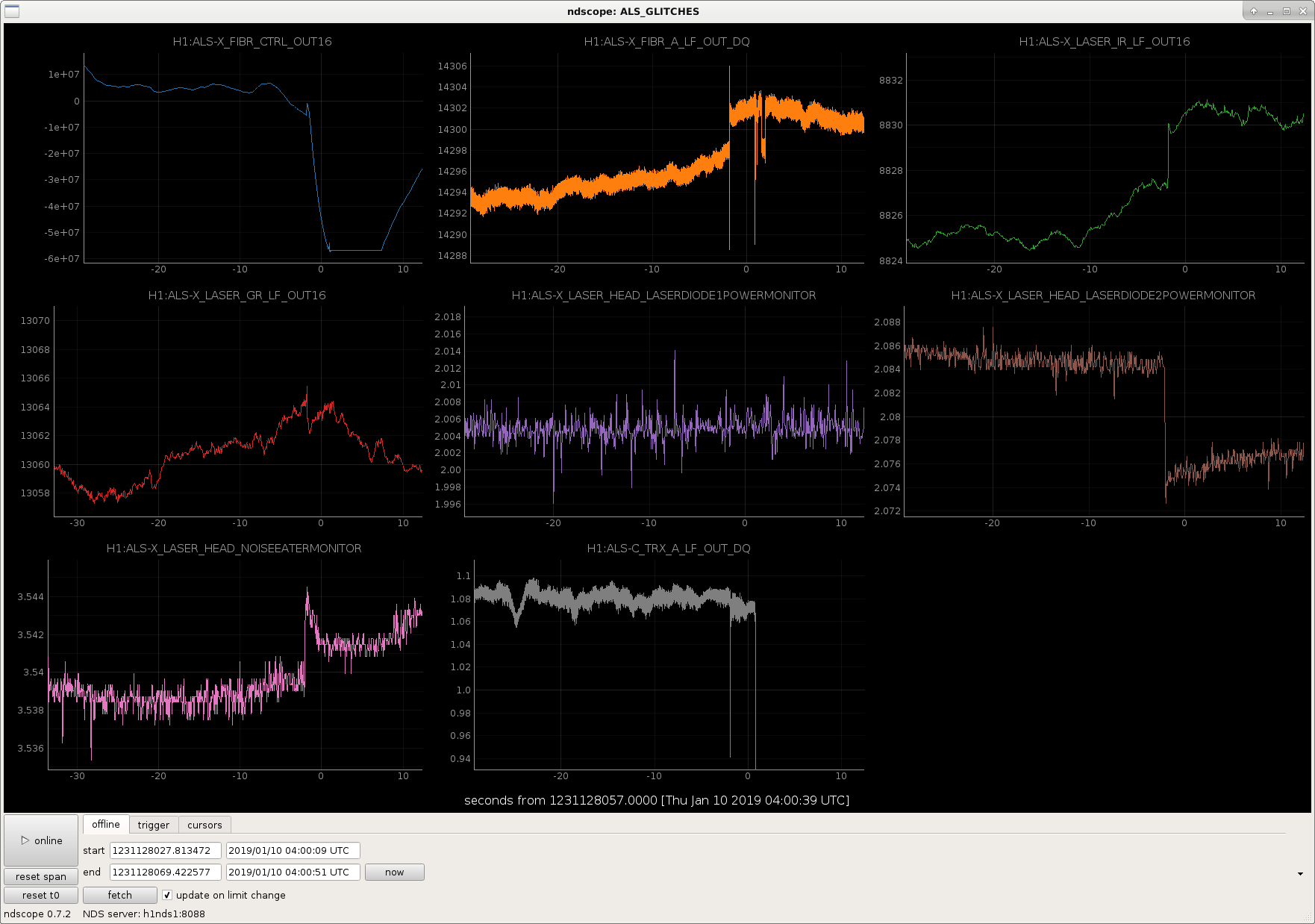
Today while locking ALS we had fast glitches in both x and y arms which caused us to lose lock. I had a quick look at the same channels I looked at when we had extra intensity noise on the ALSX laser back in September.
The glitch in the x arm coincided with a jump in a few channels in the laser: the pump diode 2 power, the noise eater, and the IR anf green output powers. We lost lock a few seconds after the glitch. First attached plot shows the glitch in green arm transmission (bottom middle), and other laser-related channels.
The y arm has glitches much more frequently than the xarm, their frequency and severity comes and goes. Looking at the same channels at the y-end during a period of frequent glitching (second attached plot) shows nothing obvious that is coincident with the glitches. There are some noteworthy things: the RMS noise on the green and IR powers out of the laser is significantly worse for ALSY, compared to X. And there are also frequency glitches in the pump diode 1 noise monitor.
Conclusion: the als-x laser maybe has some kind of intermittent mode-hopping. It's unclear from these plots what is going on with the y-arm.
Laura Nutall, Georgia, Craig, Sheila, Stefan, Thomas, Danny
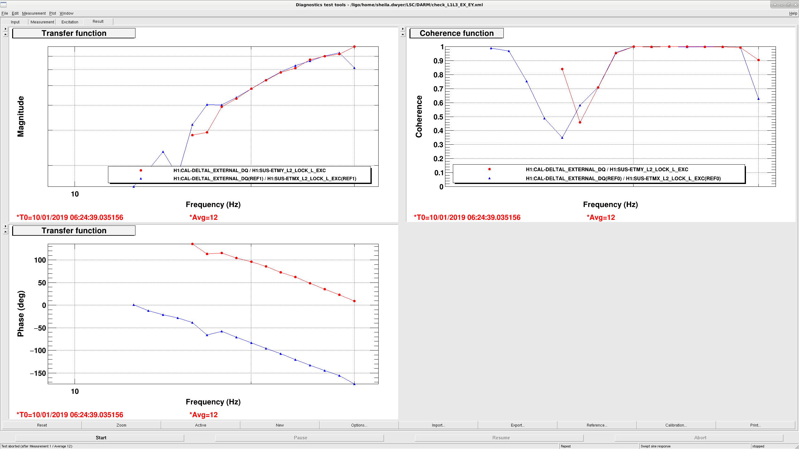
Laura pointed out this alog from Valera 42651, based on this we decided to try switching the upper stages of DARM control from ETMY to ETMX. The attached script should do the switch, some of these things need to be added to the guardian before we try to use the use_ETMX flag to go to ETMX. The attached screenshot (and template) show the measurement from L2 excitation to DARM for both test masses once we set up the actuation path. We haven't seen fringe wrapping since making the switch at 6:30 UTC. Craig has been updating the calibration, which is why our range has been changing.
Locking notes from earlier today:
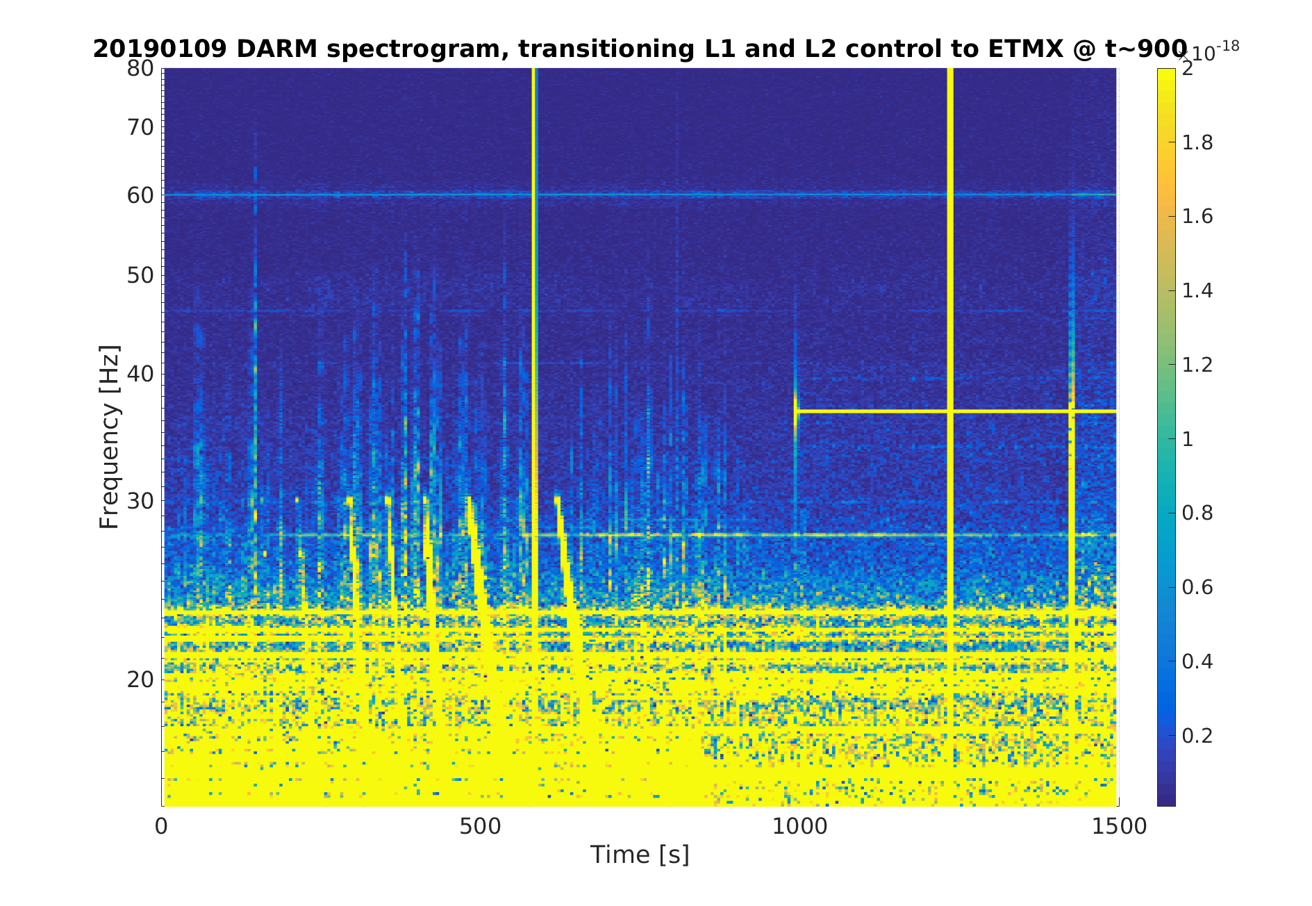
Here's a quick spectrogram from when Sheila switched DARM control from ETMY to ETMX.
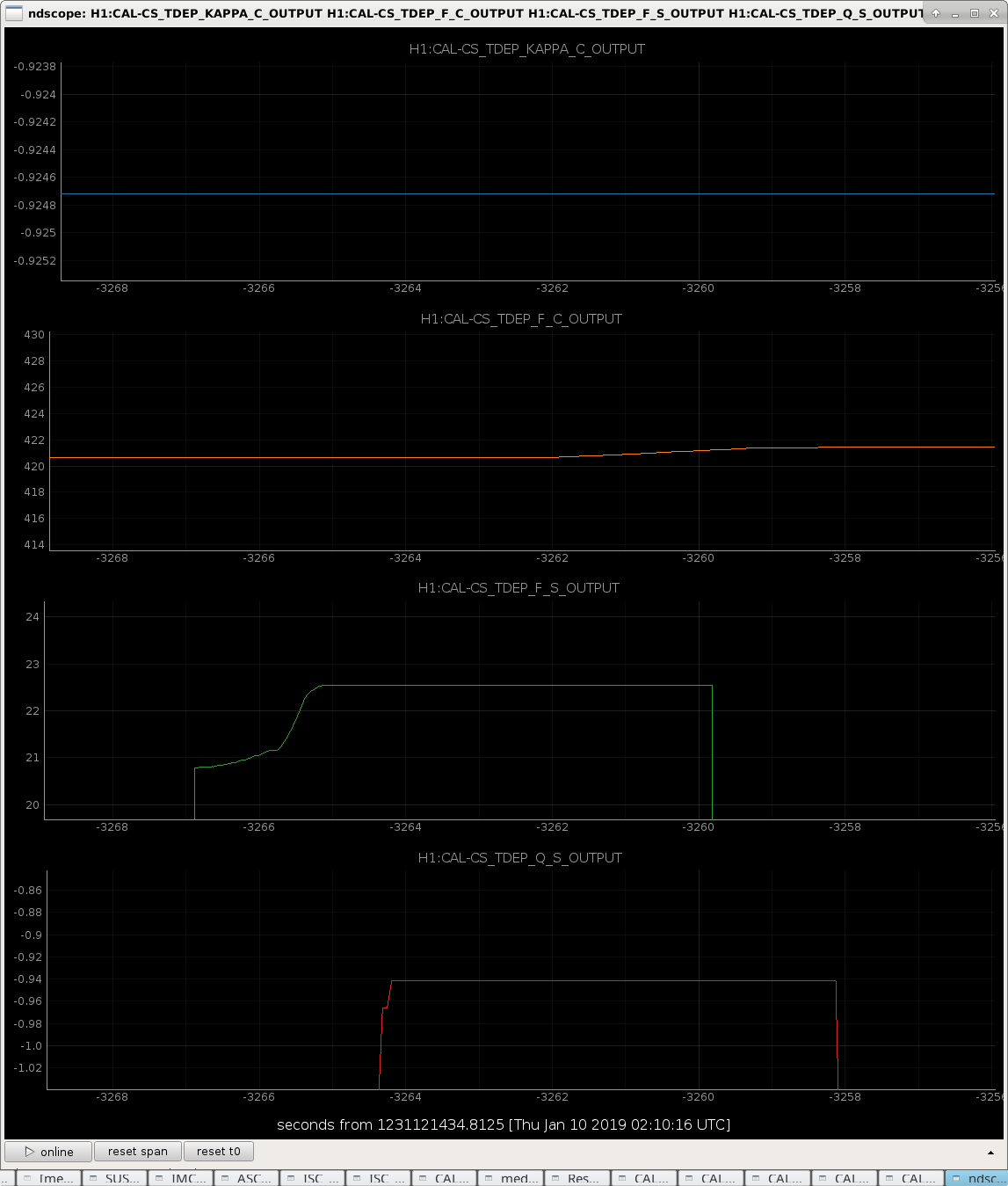
J. Kissel As mentioned yesterday/Monday, I fixed a bug that Shivaraj and Saravanan found in the time-dependent correction factor calculations for the optical plant (see LHO aLOG 46260). Woo! We managed to recover the IFO and hit nominal low noise this evening for about 30 minutes while I was present. Woo! I was looking around the new system for success, and for about 10 seconds prior to the lock loss, it was all "working" roughly as expected. This time period was surrounding Jan 10 2019 at 01:15:54 UTC -- see attached screenshot of kappa_C, f_C, f_S, and Q_S -- the optical gain, the DARM coupled cavity pole frequency, the detuned signal recycling cavity's optical spring frequency, and its Q. There still things left to be fixed before it "works" enough to start considering applying these to DELTAL_EXTERNAL: (1) Obviously, the signs are wrong (negative) on the optical gain (kappa_C) and spring Q (Q_S). This is a problem remaining with the signs of the reproduction of the various reference model parameters (aka "EPICs Records"). These have been created and installed using new(-ish) python code of which all the sign errors have not yet fully shaken out when replicating the current, mixed DARM actuation scheme. Evan and team are still actively working on this (see G1900019). (2) The gating system (which smoothes out the TDCF for application to DELTAL_EXTERNAL) and override system (which allows us to bypass non-functional parts) don't yet have all settings turned ON in such a way that the relative actuator strength changes -- a.k.a. kappa_UIM, kappa_PUM, and kappa_TST -- are spitting out live values. In this brief moment in time where the optical plant parameters were working, all of the actuator kappas were bypassed and spitting out +1.0. (3) We're still using a pre-ER13 measurement to determine the DARM loop reference model, which in turn determines the EPICs records, which determine the calculated TDCFs. The actuator measurements were quick and dirty. The IFO was still at 20 watts. Thus -- when I see that the corrective gains, the kappas for both actuator and optical plant, have magnitudes at the 10-30% level, I'm not yet sad. Now that we're electing to stick at 30W input for a while, while we hunt for noise, we should re-take -- or in some cases take for the first time -- quality measurements that will get the system to levels needed for ER14 / O3. However, with all the above qualifications -- we made good progress today. We can comfortably (albeit imprecisely) say that the optical gain needs ~10% correction, the DARM coupled cavity pole is at ~420 Hz, the optical spring is at ~15-20 Hz, and the Q is very close to critical at ~1.
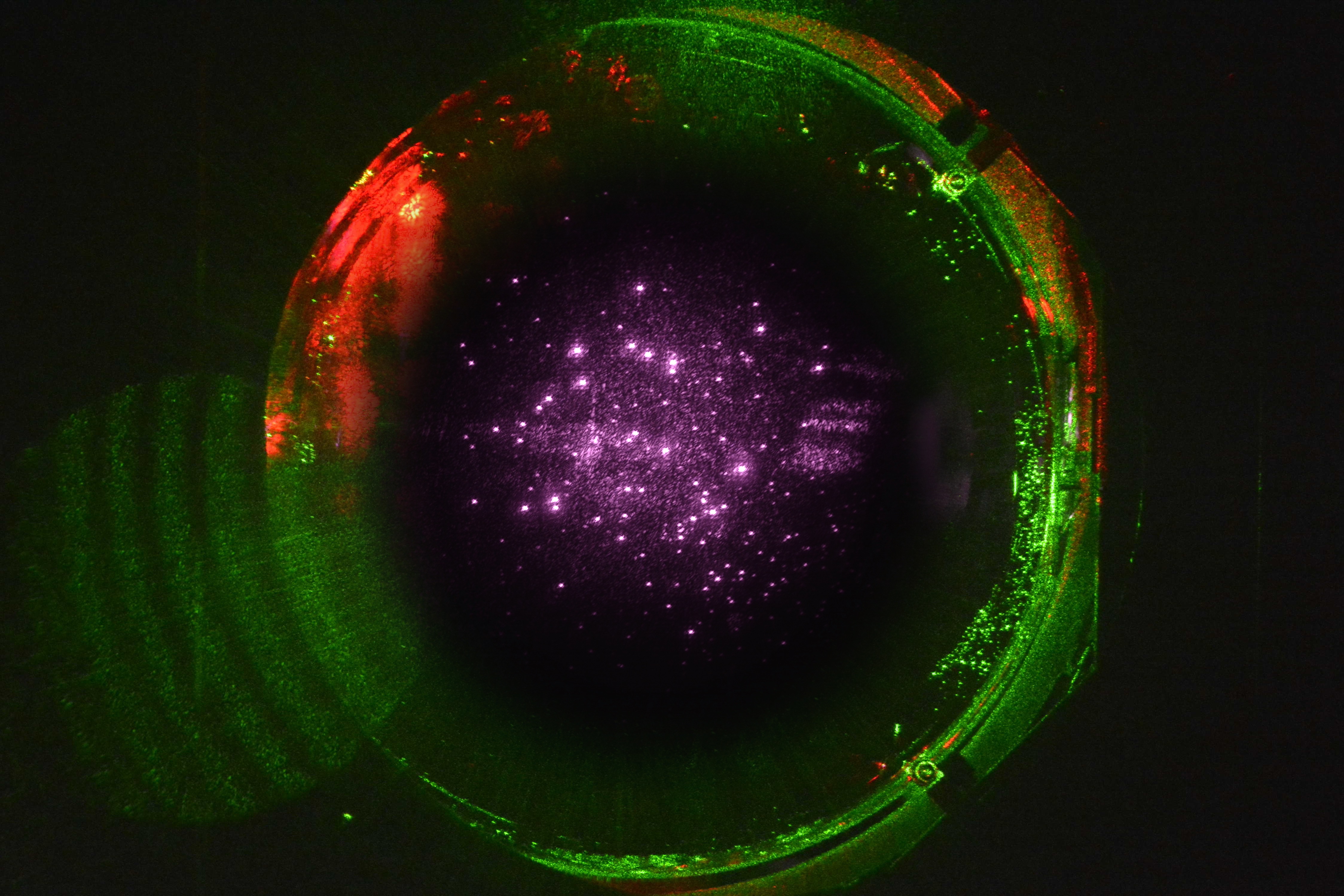
Attached below are images of the HR surfaces of the H1 ITMs with IR light resonating in the arms (19.7 W of 1064 nm laser light).
They were captured by Jeff Bartlett a few weeks ago using the "Pcal" ITM camera systems mounted on the spools at the ends of the beam tube manifolds in the LVEA, near the cryopumps.
The camera settings were:
ITM-X
#109 ISO 800, shutter 1/800
#110 ISO 800, shutter 1/400
ITM-Y
#016 ISO 400, shutter 1/500
#110 ISO 250, shutter 1/200
The assembly drawing for the camera system is LIGO-D1500073-v9.
Kentaro Mogushi's technical note regarding camera system upgrades to minimize aberrations introduced by the vacuum windows is LIGO-T1700540-v3.
Note that these are the first IR images after implementing Kentaro's upgrades. Image quality may improve slightly as the systems are adjusted.
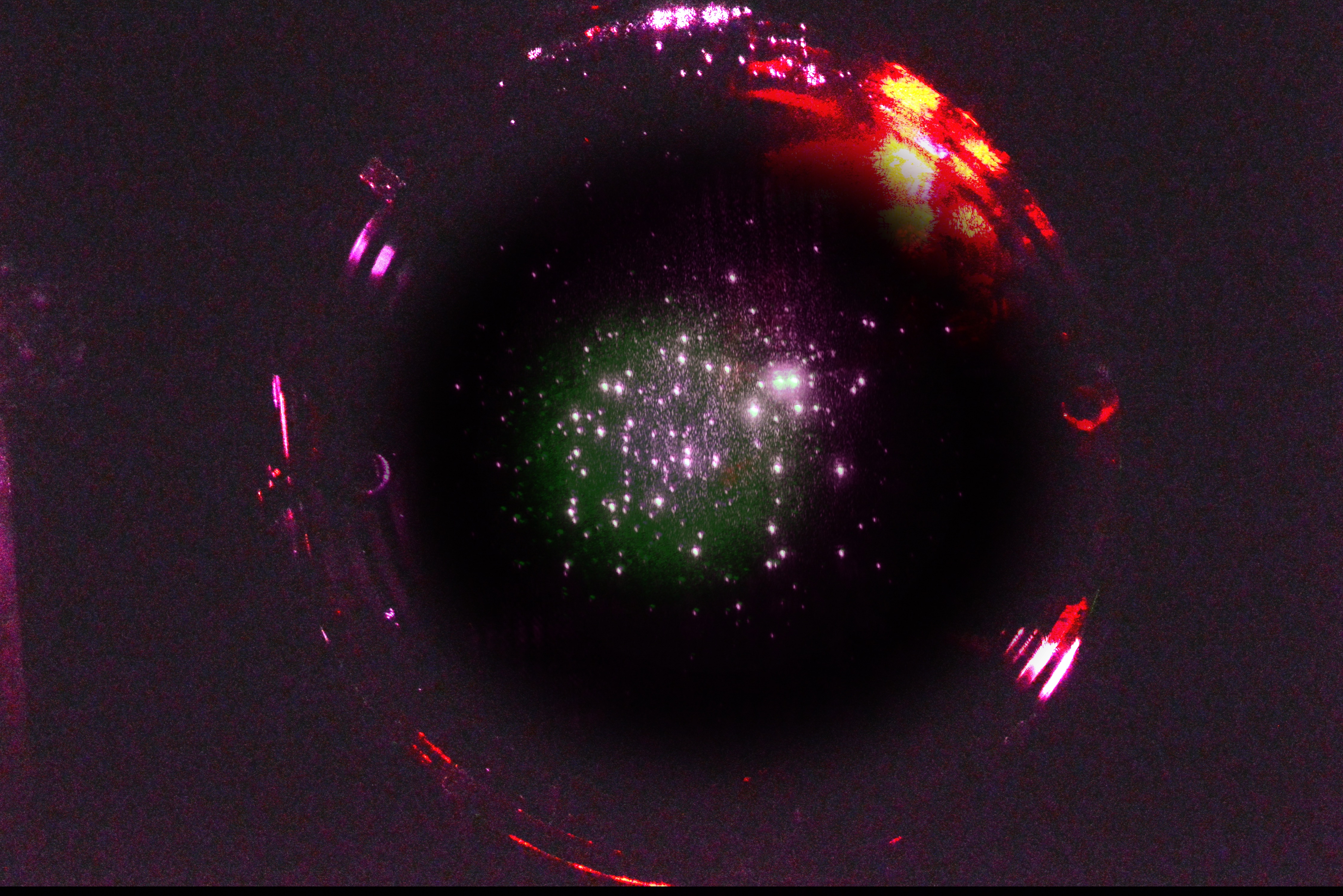
Gabriele and I were curious as to the exact locations of the spots on these images. I played with the brightness and contrast of ITMY until I could see some fiducials of the cage structure (in this case, the EQ stops on the right hand side of the image - see first attached image). Then, I super-imposed this on an old image of ITMY from aLOG 42520 that showed the cage structure much more clearly. The results are attached:

The camera position is fixed (physically locked down), the suspension cage is also fixed, and the position of the heads of the EQ stops are well known. By using the EQ screw heads as the zero position, the location of spots on the optic face can identified. I made a conscious decision in these frames to turn down the exposure to accent the surface spots. In most the position of the EQ screw heads are visible.
Here's ITMX blended with images from aLOG 43174 and aLOG 42774

J. Driggers, S. Dwyer, J. Kissel, P. Thomas Prior to yesterday's rebooting of most front-end machines (LHO aLOG 46288), Patrick, Jenne, Sheila, and I went through the SDF system and reconciled differences. I attach the highlights of what we accepted (into the SAFE.snap files -- OBSERVE.snap files were NOT reconciled). The highlights come mostly from the ISC systems that are infrequently maintained. This may (or may not) be useful as (a) a recovery aide today, and (b) a record / indication of the progress / changes in the global control system over the past few weeks and the holidays -- especially as some of the team responsible for the changes have left the site for good. h1asc model: - Accepted changes to the TR X/Y and A/B QPD to DHARD and DC5 to elements of the ASC input matrix. This reflects the changes made by Hang before the break to implement the radiation pressure compensation (RPC) stystem (e.g. LHO aLOG 43849). These elements of matrix were last changed in mid-December (e.g. Dec 14, 23, 26 , and 28) - Several other Radiation Pressure Control TRAMPs were accepted as is. - Accepted the reduction of the CHARD Y A gain from 1.4 to 1.35, and the turning OFF of the DHARD Y B loops by setting the gain to 0.0. This is something we don't necessarily want to keep, but was part of the spot position exploration vs. TMS drift on Monday night. - Accepted the CHARD Y to ITMX element of the ASC output matrix at 0.87 (where it had been saved [accidentally] in December as 0.93, which everyone agreed is very wrong). - Accepted ASC_AS_A_RF45 I and Q individual segment filter gains as 1.0 instead of 1.413. These had accidentally been saved in the SAFE.snap because two weeks ago, we were reconciling SDFs in a state just before nominal low noise. That means we were *past* the state that reduces the RF45 modulation depth, and compensates that optical gain change by increasing the gain of the AS_A_RF45 sensor from 1.0 to 1.413, which we *do* want when we're in nominal low noise -- i.e. when we reconcile against the OBSERVE.snap -- but now when we're DOWN, or in low acquisition states -- which is what we want after computer reboots. Thus ACCEPT as 1.0. - Accepted any and all ASC-ADS (alignment dither system) changes in filters, gains, limiters, tramps, oscillator frequencies, etc as is. These are all a part of the new dither alignment system mentioned above. Most were changed on Dec 21 with the system was installed (LHO aLOG 46136). h1ascimc model: - Accepted MC2 TRANS QPD SEG[1-4] FM9 filter = "+9dB" gain as OFF. This filter was originally installed in concert with a -9dB analog whitening gain in mid-December when Sheila found that we had saturated the QPD's ADC before a high-power lock loss on Dec 21 2018 LHO aLOG 46084. However, whether it be from settings loss or intentional, the analog whitening gain was restored to "nominal" +36 dB gain a day later, and then the compensating gain filter was turned OFF a few days after that. Somehow, in those three days, though, someone saved with compensating filter as ON in the SDF file. Since the analog whitening gain is no back to regularly being at +36 dB, there is no longer a need for this +9dB compensation filter to be on. It's been accepted as OFF. h1lsc model: - Accepted changes to the LSC output matrix elements for OSC 1 2 3 to PRM, SRM, and BS matrix as now regularly ON (with whatever values were present). This is the part of the new length dither line system to constantly monitor the length loop gains during power up. LHO aLOG 46082 - Reverted LSC PD DOF matrix (the DRMI 3f input sensing matrix) elements as ZERO. The safe.snap file correctly indicates that the DRMI 3f matrix elements should be zero when the IFO is down. The current EPICs values were non-zero because the last lock loss was during a DRMI 3f lock, and the elements hadn't been reset. - Reverted the LSC TR X NORM OFFSET from -0.36 to 10. This offset (as far as we can tell) isn't used, but it's been 10.0 for a very long time prior to its change on Dec 21. Also the LSC TR Y NORM OFFSET is also 10. No findable aLOG, so we reverted. h1lscaux model: - blindly accepted all ~110 differences. h1omc model: - Accepted the change in filtering of the OMC-LSC_PD_IN bank -- the first filter bank on the way to the OMC length control that band-passes the OMC DCPDs. The OMC length dither line band pass was reduced from "BP4100" in FM5 = [4000 4200] Hz to "nBP4100" in FM7 = [4050 4150] Hz on Dec 31 -- see LHO aLOG 46197. h1susbs model: - Accepted FM10 = "BounceRoll" in the BS M2 LOCK L filter bank as OFF. This is the Beam Splitter's Bounc and Roll mode notch. It's unclear why it's off, but it's been this way for quite some time, so I accept it. h1susitmpi model: - Reverted all UPCONV output matrix elements to 0.0. This matrix last had values changed and populated while Sebastien and Terra were here getting Qs of test mass mechanical modes in early December 2018 (LHO aLOG 45812), and are no longer needed. - Accepted all oscillator frequencies. Generic Things Across Models: "QPD Offsets" - Any and all QPD and WFS OFFSETs have been accepted as is in h1asc, h1ascimc, h1omc, h1alsex, h1alsex, h1iscex, and h1iscey. As we're continuing to explore and find the optimal spot position for the interferometer -- especially after we've switched to an ETM alignment dither system (see e.g. LHO aLOG 46272) -- these will be occasionally updated. "A2L gains" - these DRIVEALIGN P2L and Y2L gains across many globally controlled suspensions (like h1susetmx, h1susetmy, itmx, itmy, even h1susmc2) are coupled with the above mentioned exploration of spot positions. Jenne says, theoretically, with the new ASC dither system, we should no longer be regularly updating these, so we've accepted them as is. "Not28Hz" filters - in h1asc model, accepted DC 1 and 2 "Not28Hz" filters (FM9 for P and FM5 for Y) as ON. The crowd didn't have a satisfying answer for this resonant feature that intermittantly gives us problems, moves around in frequency, and/or may be solved -- according to a Dec 19th LHO aLOG 46084 after some commissioning of ASC loops. - in h1susbs and h1susetmx models, accepted 28.75 Hz filters as OFF. We should probably go on a campaign of removing these filters now that the problem has been solved.
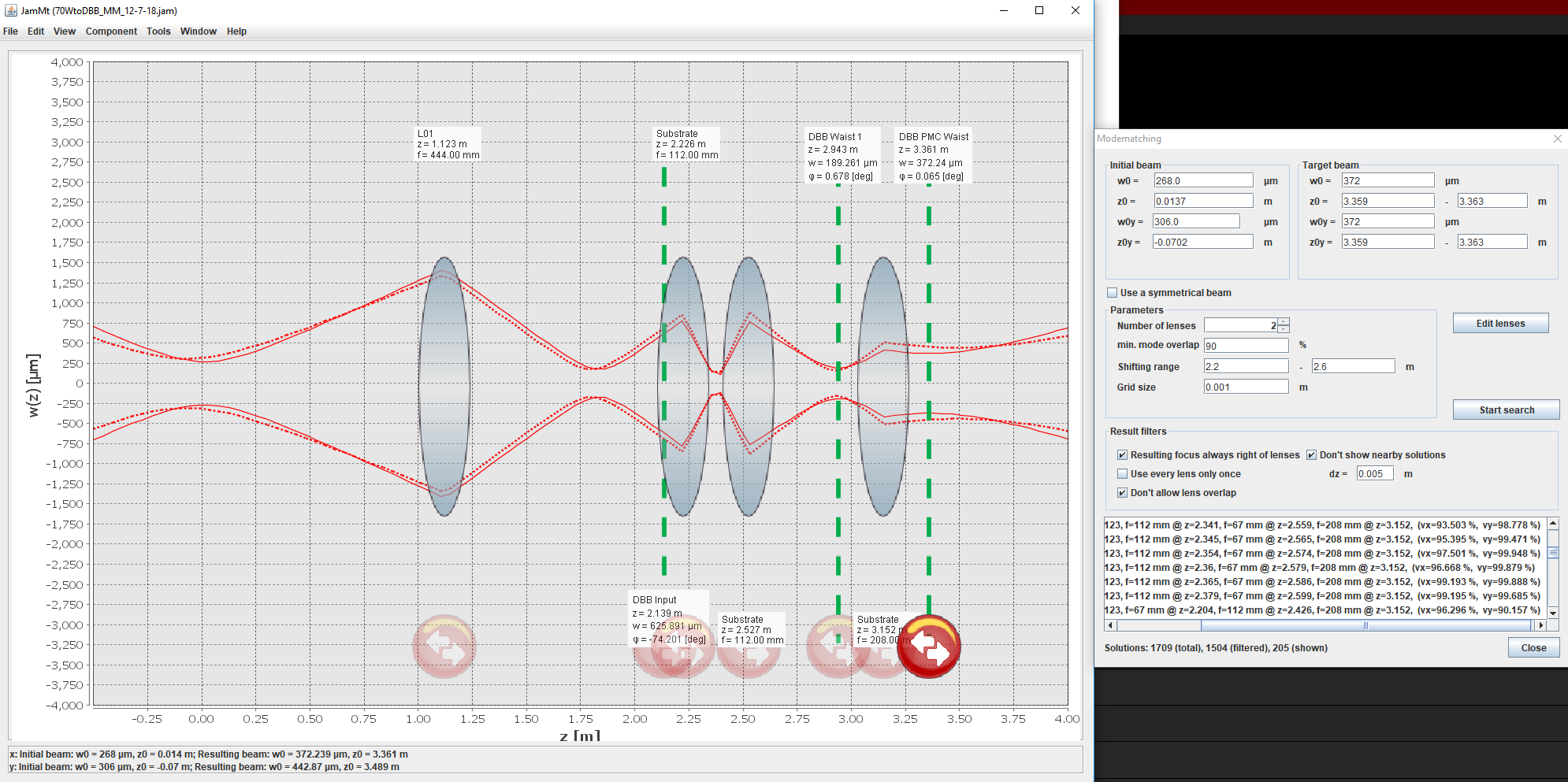
During yesterday's maintenance window I worked on getting the DBB up and running. I implemented the mode matching solution shown in the first attachment and proceeded to align the DBB. That completed I then tweaked the mode matching lens positions to optimize the mode matching to the DBB PMC. I ended up moving the 1st mode matching lens 2.5mm towards the 70W amplifier, and the 2nd mode matching lens 11.2mm away from the 70W amp. At this point the maintenance window was running short and further position tweaks only made the mode matching worse so I stopped here. A single FSR scan of the DBB PMC is attached to show where I left things (see 2nd attachment). The mode matching isn't quite as good as the last solution (implemented before the changes during the Nov vent, which rendered that solution invalid), the 20+02 peaks are higher but more equal than previously; it's possible some more lens position tweaking could improve this (will be explored during a future maintenance window).
I then tried to lock the DBB PMC, but once again it was unable to lock. I looked into the locking threshold for the DBB PMC and then noticed something that I hadn't when I last worked on the DBB: the DBB PMC transmitted photodiode (TPD) was not registering a voltage on MEDM. This voltage is used as the locking threshold for the DBB PMC, and it consistently read zero. I hooked up a multimeter individually to each port of the DBB PMC TPD (0dB, 40dB, and 80dB) and all 3 were indeed outputting a voltage. Using the DBB's Manual mode, I manually moved the DBB PMC PZT and watched the voltage from the 0dB port change accordingly: as the DBB approached resonance the TPD voltage increased, as it moved away from resonance it decreased (all expected behavior). Plugging the DBB cables back in and repeating the same experiment showed absolutely no change on the MEDM screen. To get a more full picture, during the next maintenance window I will repeat this for the 40dB and 80dB ports of the DBB TPD (as I only used the 0dB port due to time constraints), although this likely explains why the DBB PMC won't lock; its resonance condition can never be met if the readout is not functioning correctly. We will start hunting this down to get it fixed.
As a last item, I did a quick 1 minute duration Mode Scan (since it doesn't involve a locked DBB PMC) just to see what the higher-order mode count of the 70W beam is (as read by the DBB PMC). I've attached the resulting measurement (3rd attachment). It claims the 70W beam's higher-order mode content is 41.1% +- 9.666%. This cannot be right as at last measurement we had a PSL PMC visibility of ~89%; I also checked the PMC after seeing this result and it was transmitting ~55W and reflecting ~11W (83% power throughput, which would be impossible if the higher-order mode content of the beam was really 41%). So something is still off here, be it alignment, mode matching, or something else. I will try to tweak up the mode matching and alignment to see if I can get the mode matching better (at least close to the previous solution) and see how this changes the Mode Scan measurement; if this doesn't work, a new mode matching solution will be explored. Should that fail, then we may be in the "something else is wrong here" category. It should be noted that LLO is experiencing a similar issue with their DBB; we're currently in communication with AEI to see if we can get this figured out.
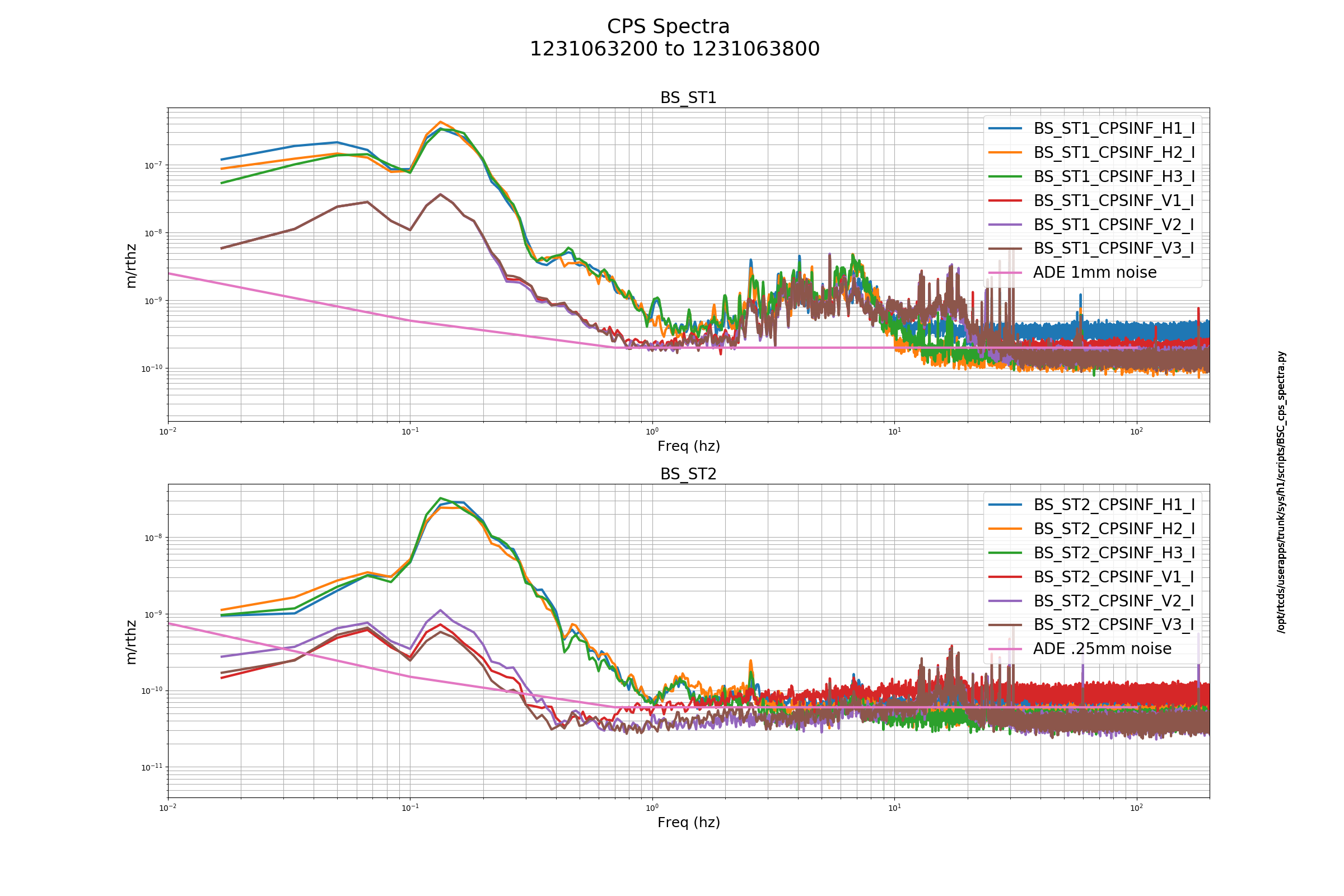
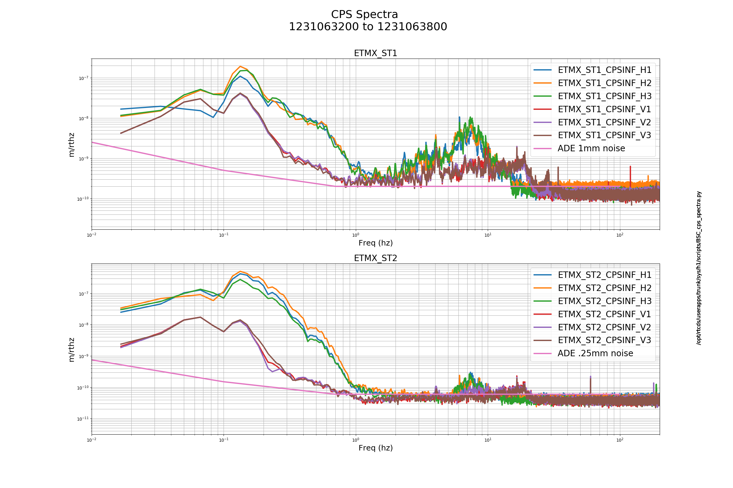
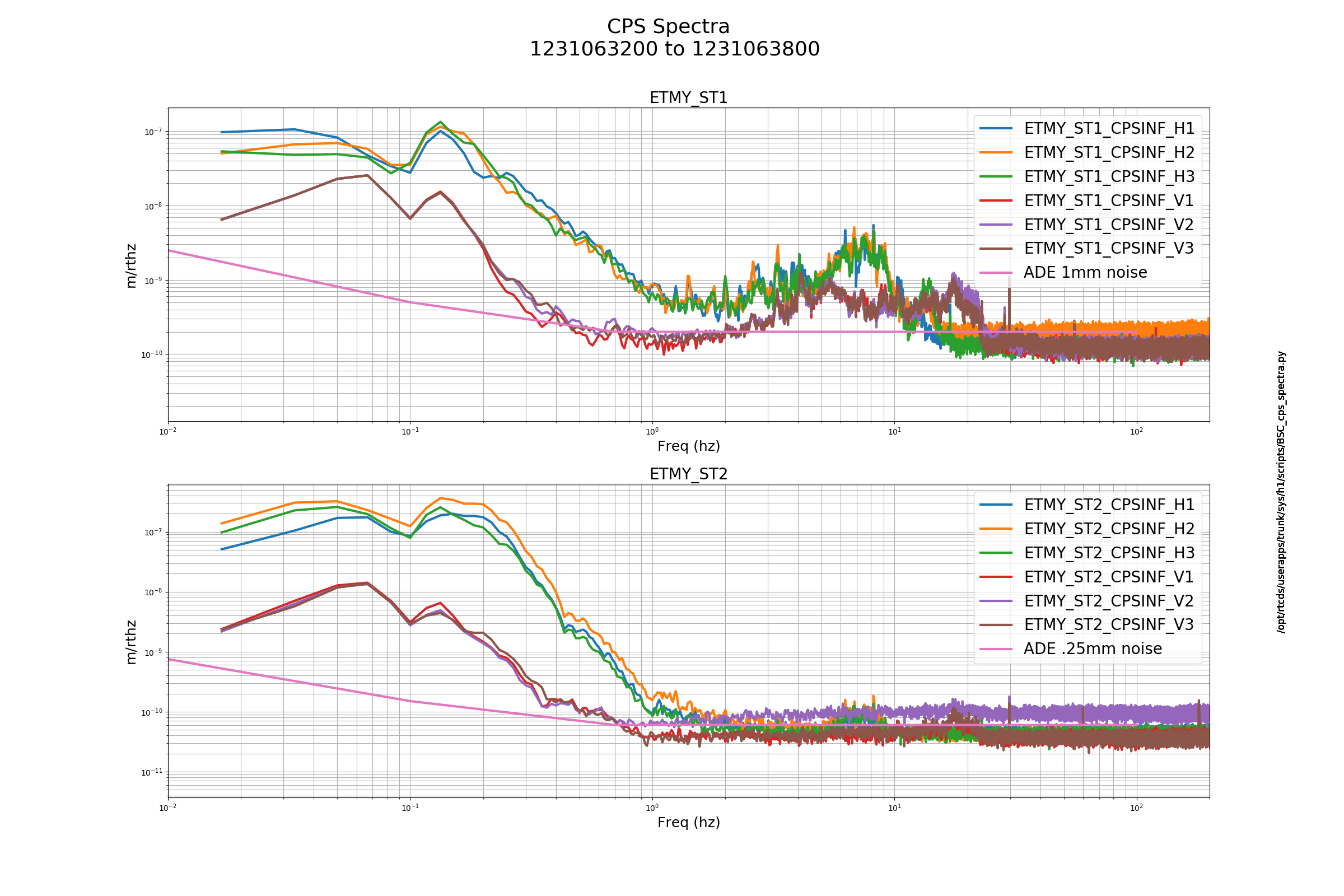
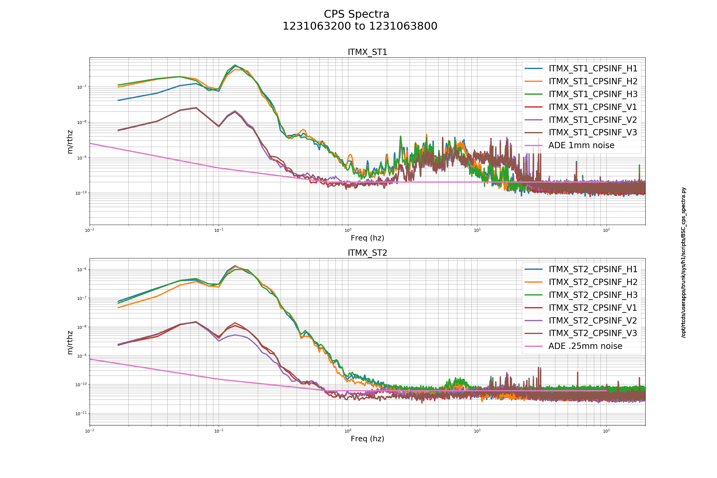
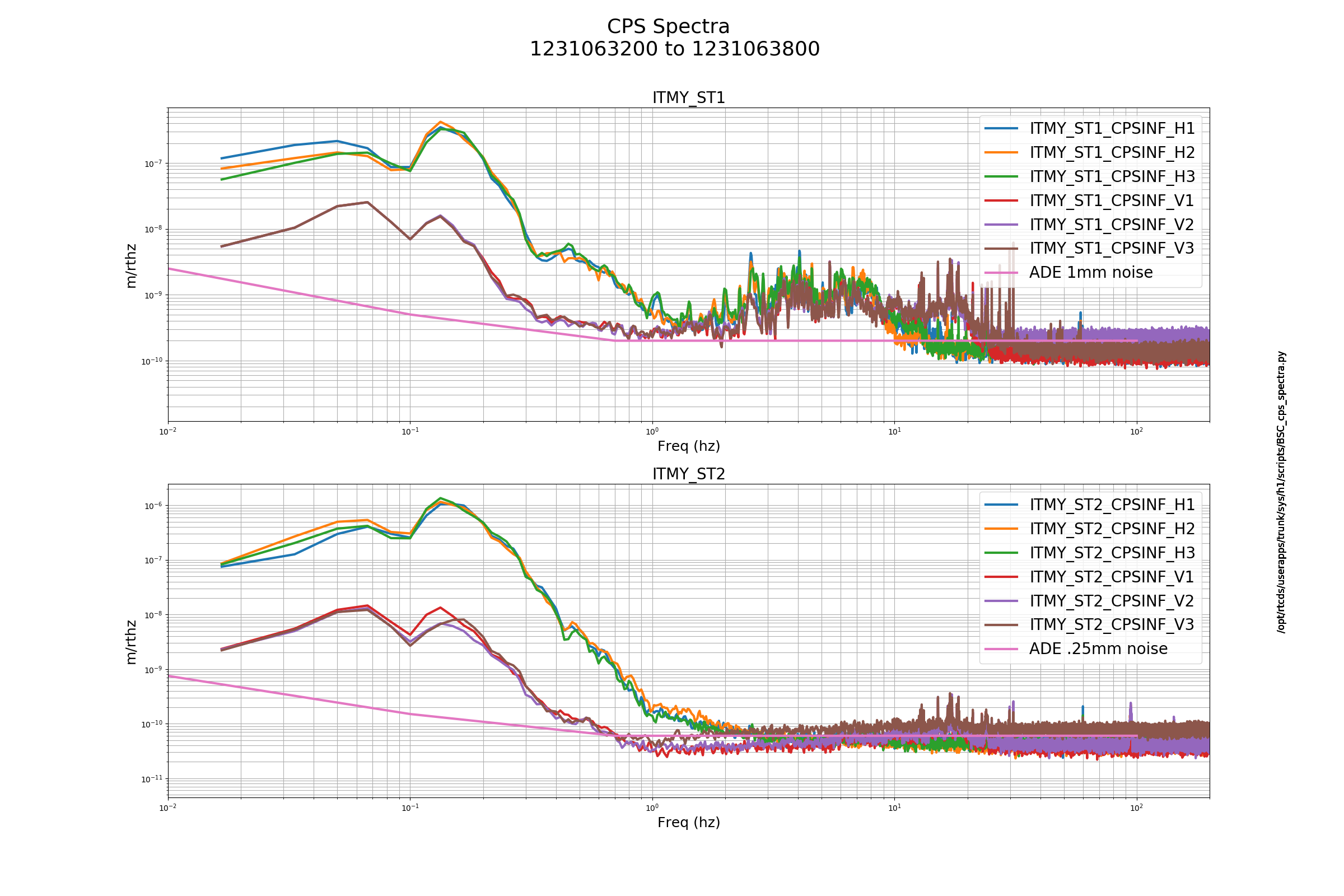
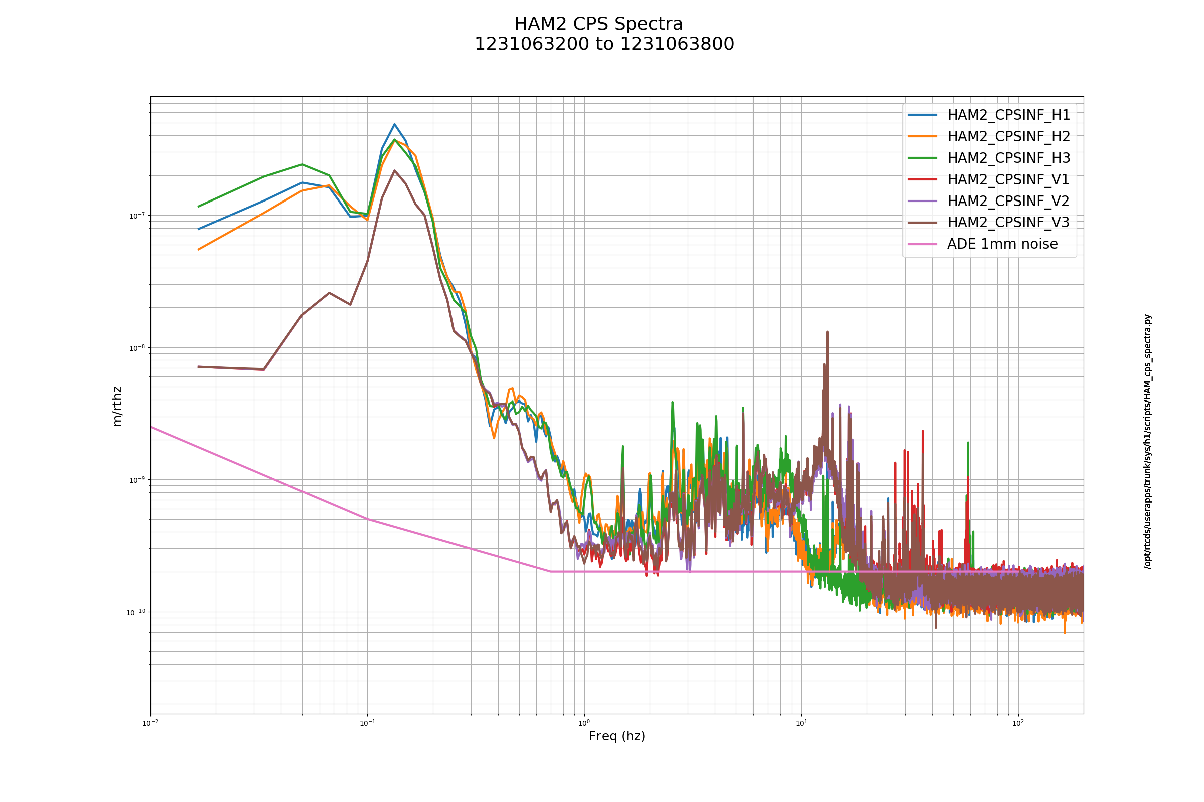
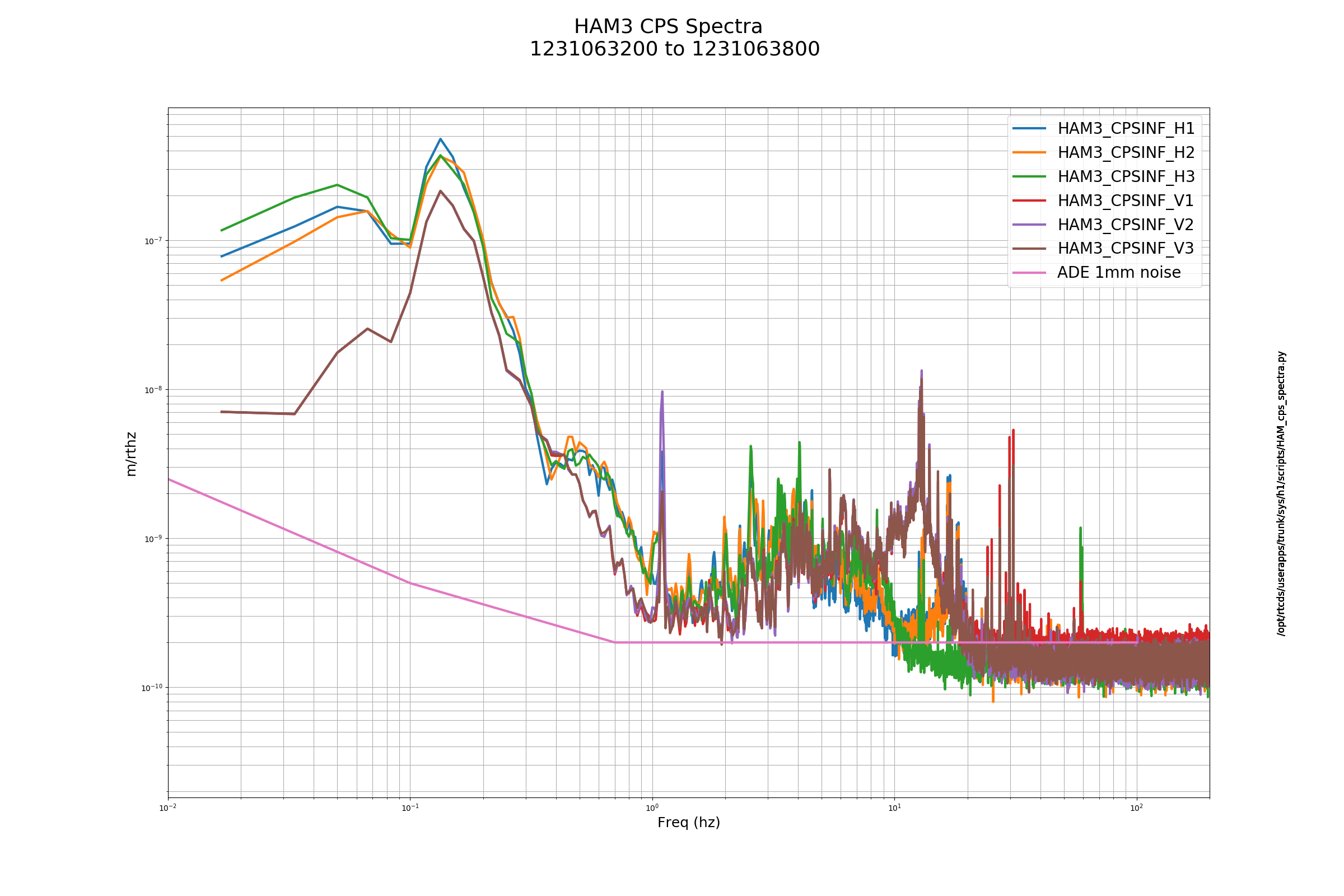
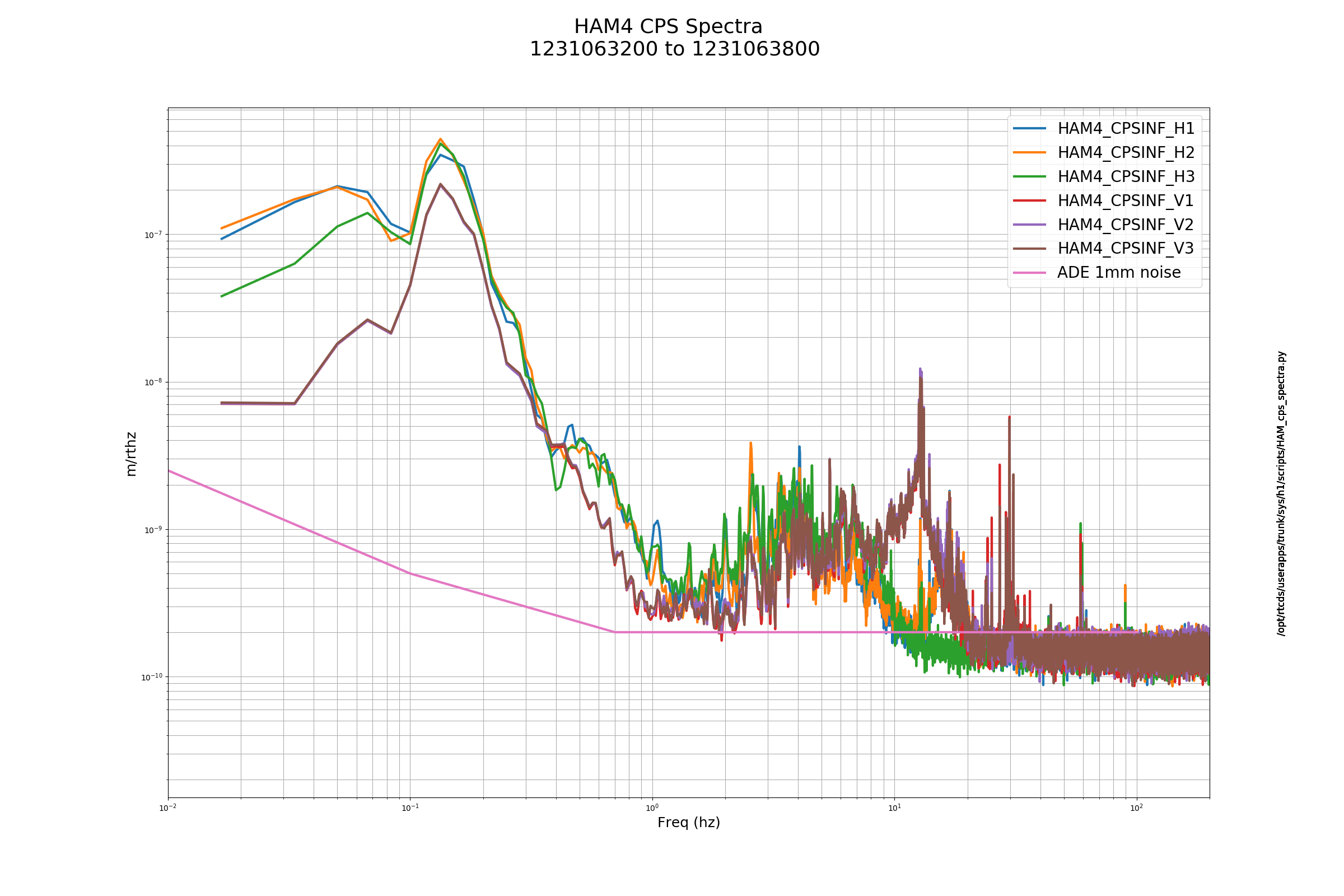
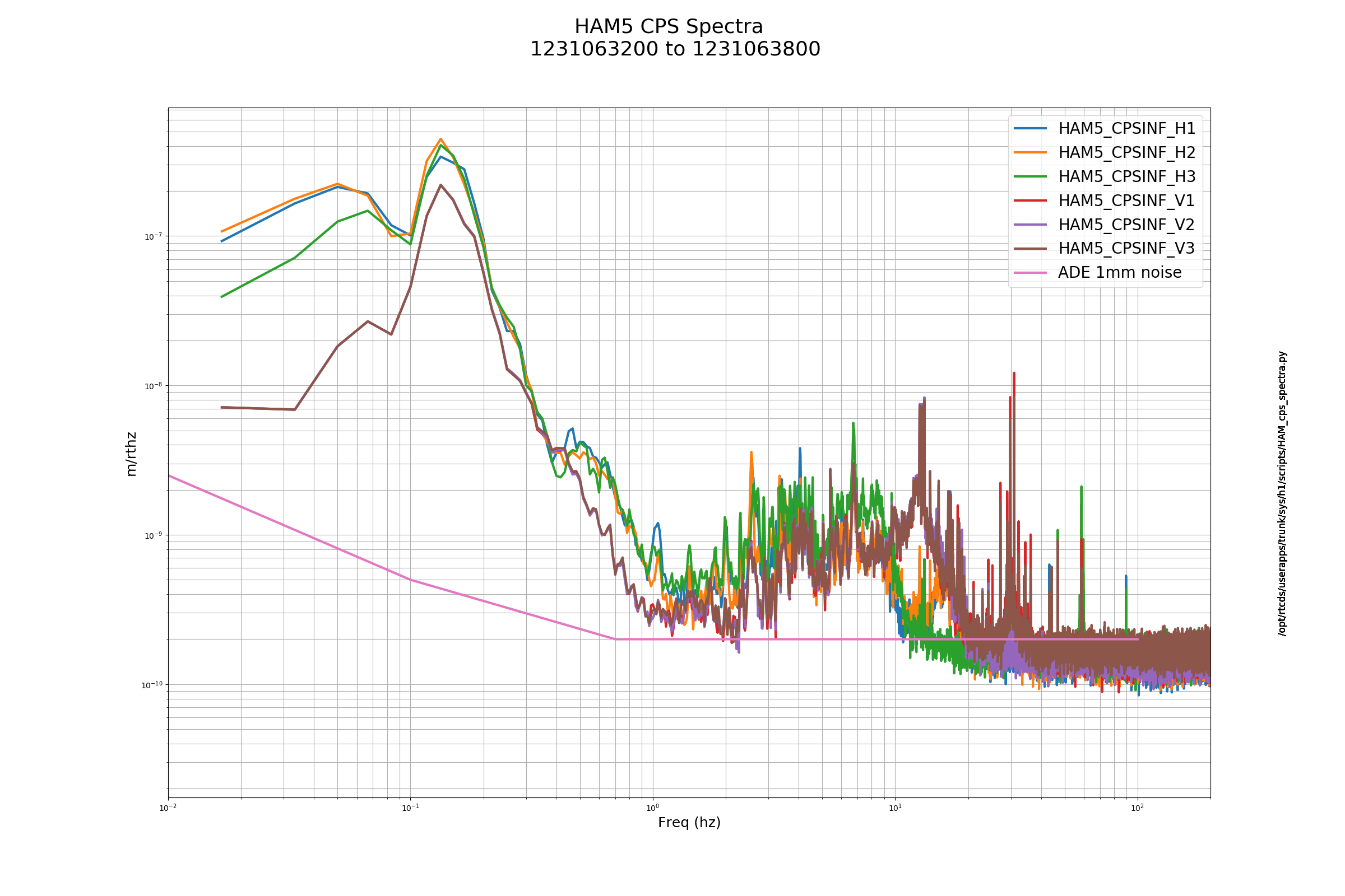
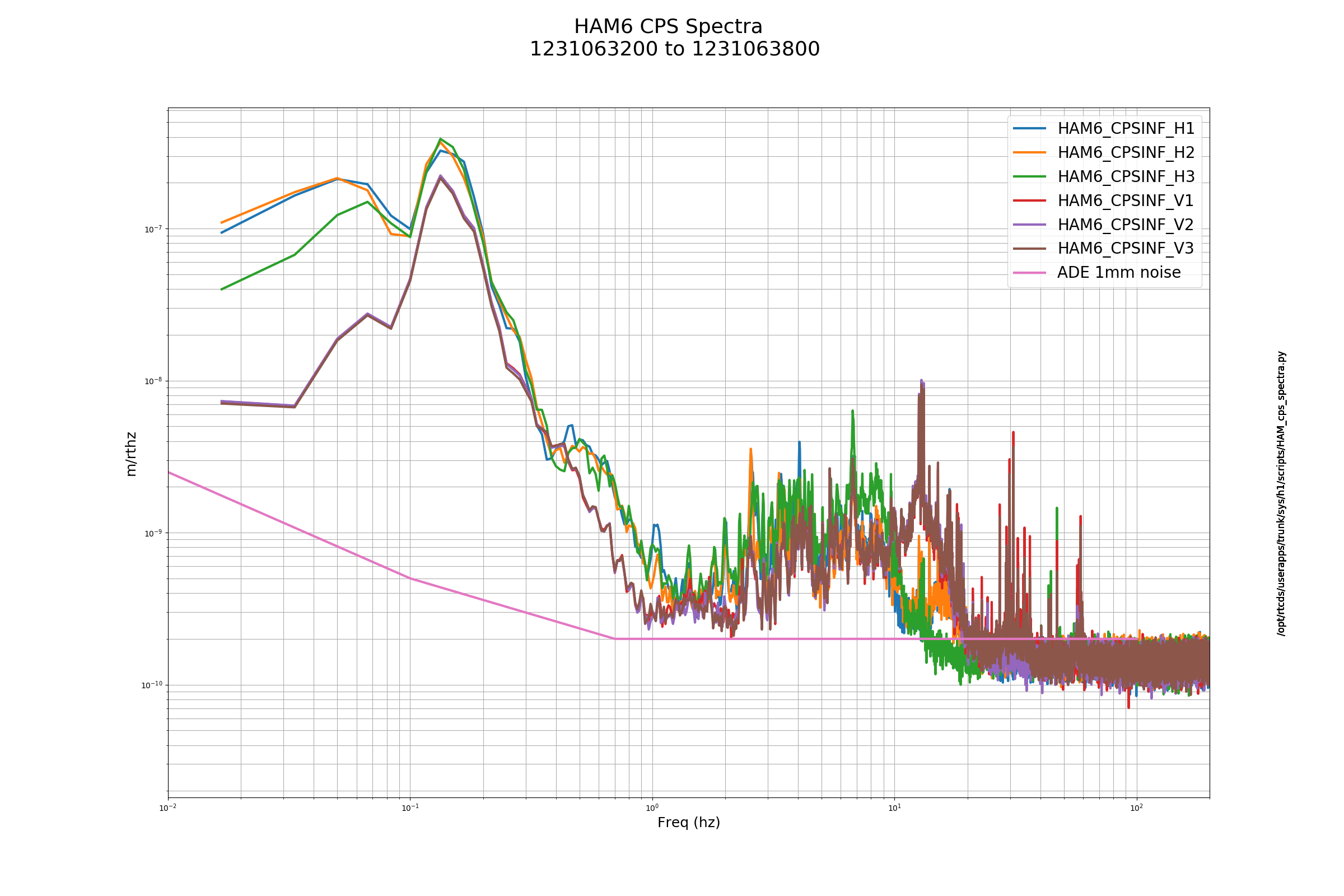
FAMIS 8086 The following appear elevated: ETMY_ST1_CPSINF_H2 ETMY_ST2_CPSINF_V2 BS_ST1_CPSINF_H1_I BS_ST2_CPSINF_V1_I ETMX_ST1_CPSINF_H2 ITMX_ST2_CPSINF_H3 ITMY_ST1_CPSINF_V2 ITMY_ST2_CPSINF_V3
15:40 UTC Vanessa to end X. Karen to LVEA. 16:29 UTC Karen back 17:12 UTC Gerardo and Filiberto to X-28 and Y-28 and mid station 17:14 UTC Nutsinee to ISCT6 17:24 UTC Ed to LVEA to reset HAM6 dust monitor 17:50 UTC Kyle back and forth between mid X and mid Y 18:06 UTC Chris opening rollup door, then to mid X 18:27 UTC Gerardo and Filiberto back 21:44 UTC Keita and Daniel to LVEA, work on ISS second loop 22:01 UTC Travis to end Y 22:03 UTC PSL tripped off, rack work 22:12 UTC Keita and Daniel back 22:23 UTC Travis to mid X 22:34 UTC Travis back 23:00 UTC Site weekly meeting
FAMIS 10491 Added 50 mL H2O to the H1 PSL crystal chiller. The canister filters are white and free of debris. There are no faults on the diode chiller.
Following up on alog 46240, we made the following mods to the ISS Second Loop, S/N S1700062, which is now installed again (PCB D1600298):
To account for the increased analog gain we reduced the VGA gain to 0dB (from +20dB). We increased the REFERENCE_IN_MTRX_1_2 gain to 10 (from 1) and the REFERENCE_IN_MTRX_1_4 gain to 0.5 (from 0.05). The reference offset was also adjusted to 537 (from -35.14). At first glance, the output offset fluctuations are significantly reduced.
H1:PSL-ISS_SECONDLOOP_REFERENCE_IN_MTRX_1_4 is controlled by IMC_LOCK guardian, so a factor of 10 was put into that (i.e. 0.5 from 0.05 for AC coupled, and 50 from 5 for DC coupled 30W).
Also we noticed that 10Hz pole on/off indicator for 3rd loop and slow offset path on the front panel was not working (it never turned on), but the readback was working and the pole seemed to be switching.
[PatrickT, Jenne]
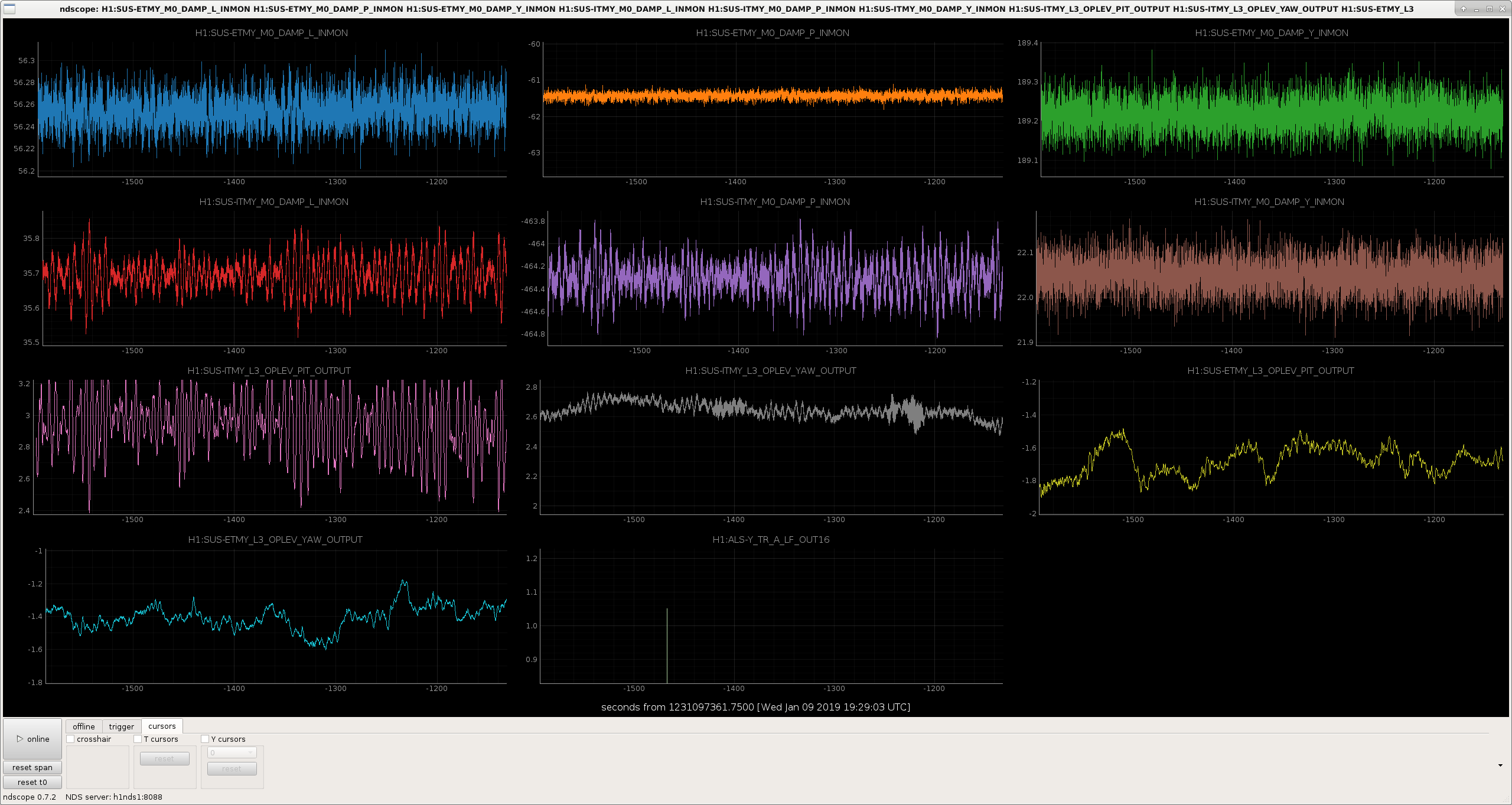
We've struggled to keep Yarm ALS locked this morning since we have particularly bad ground motion today. We started down a path of trying to figure out why.
The Yarm SUSPOINT length projection from the seismic tables doesn't seem very coherent with the power fluctuations in the Yarm. This led us to look at the angular motion of the optics.
In the attached ndscope figure, you can see that the oplevs for ITMY and ETMY, pitch and yaw are on the same y-axis range of 0.8 urad. However, ITMY pit is moving more than this scale. (Stefan has some plots up that show that a similar phenomenon is happening on the Xarm).
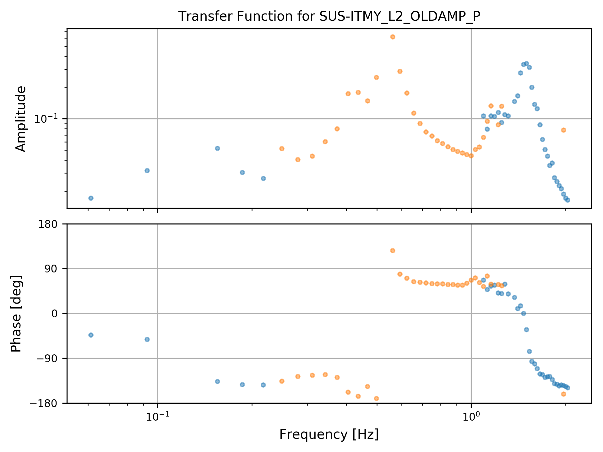
We took a measurement of the ITMY pit oplev loop, with a thought toward using the oplev to damp this motion. However, before we go further down this path, we're looking with Sheila and Stefan if there are any inconsistencies in the seismic isolation or suspension top stage damping that may have potentially come in during some maintenance or computer reboot time.
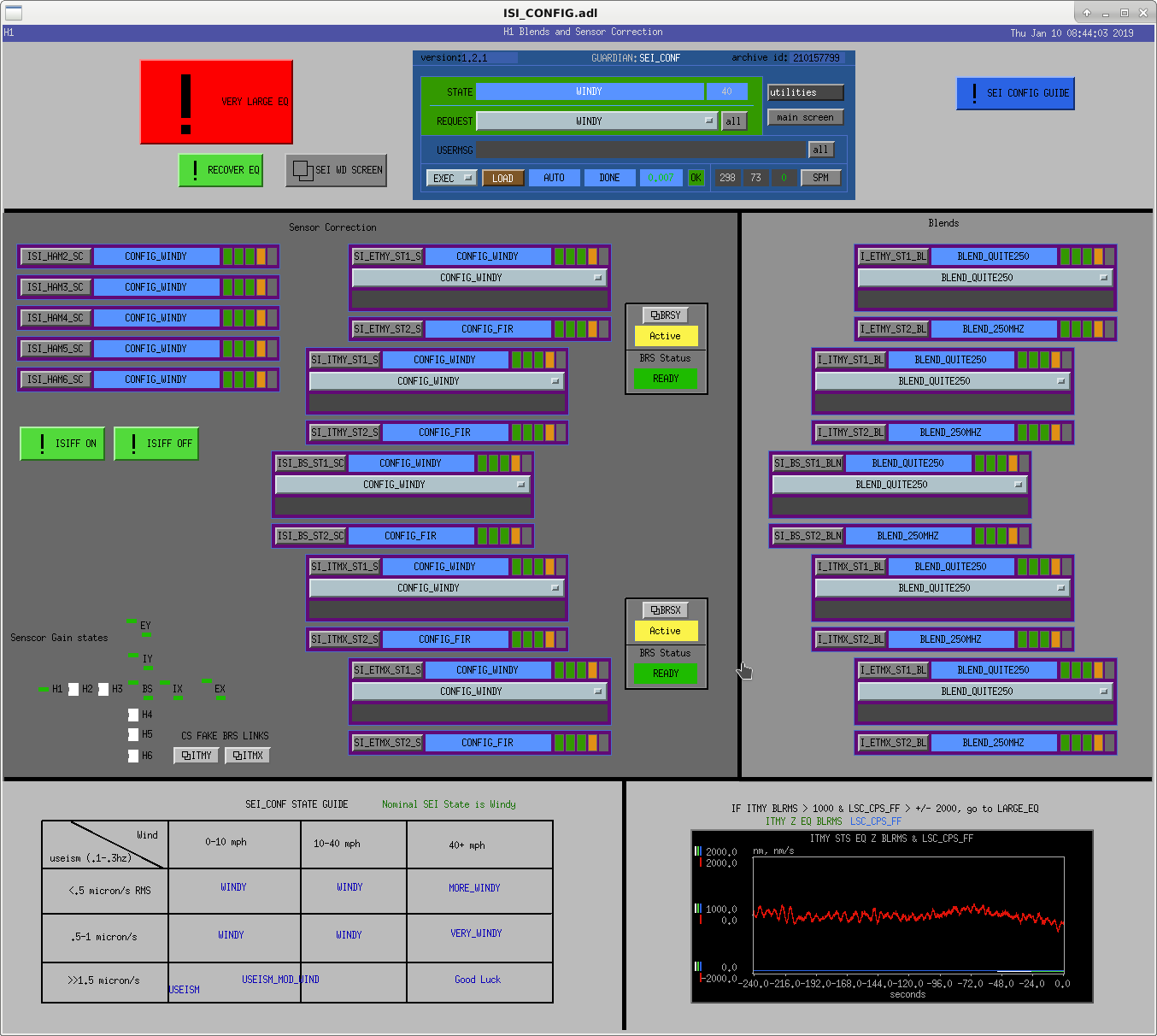
I've added links to BRS overviews for the non-existent CS BRS to the ISI-CONFIG screen so we have an easy way to check the status of these paths in the future. They're in the bottom left quarter of the screen, above the configuration guide. I had to modify the ITMX/Y bsc-isi macros to get them to work, which breaks Hugh's clever "Not Built" labels on the ISI overviews.
*This comment is a follow up to the comments below. Why is this post appearing above the earlier comments? It makes no sense out of order...*
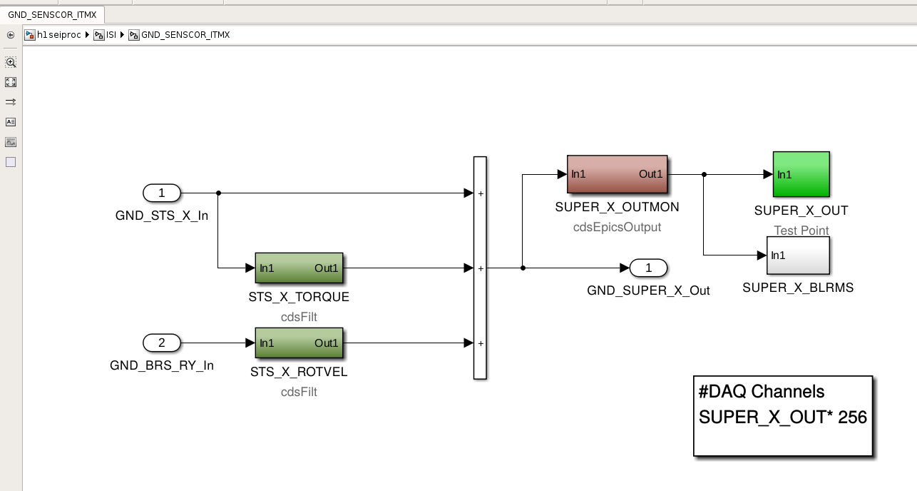
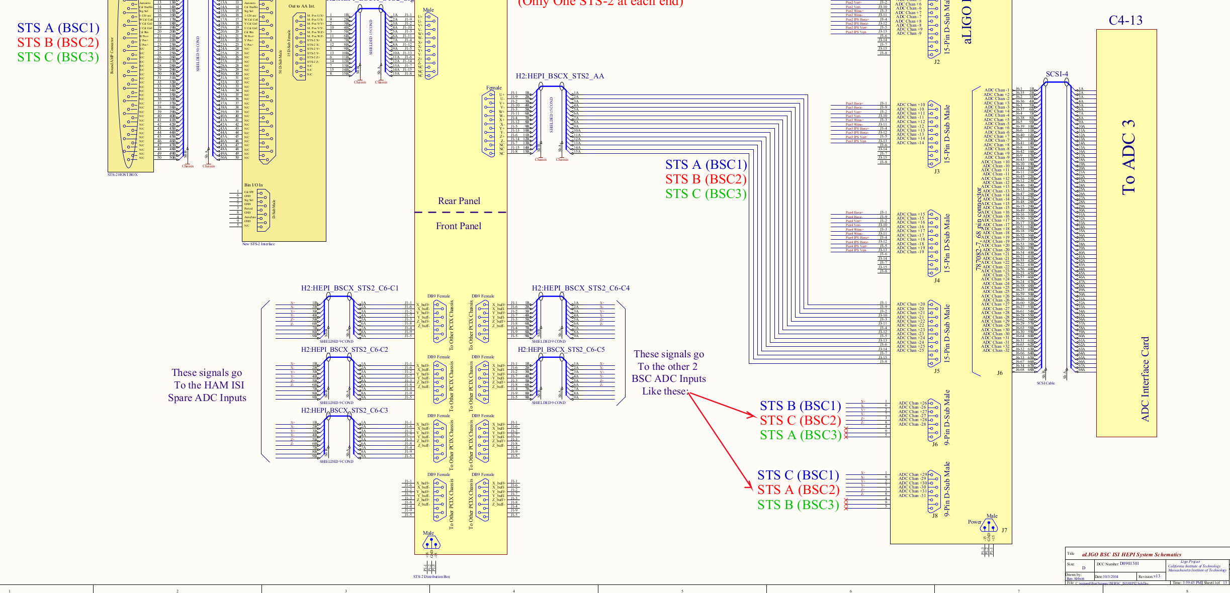
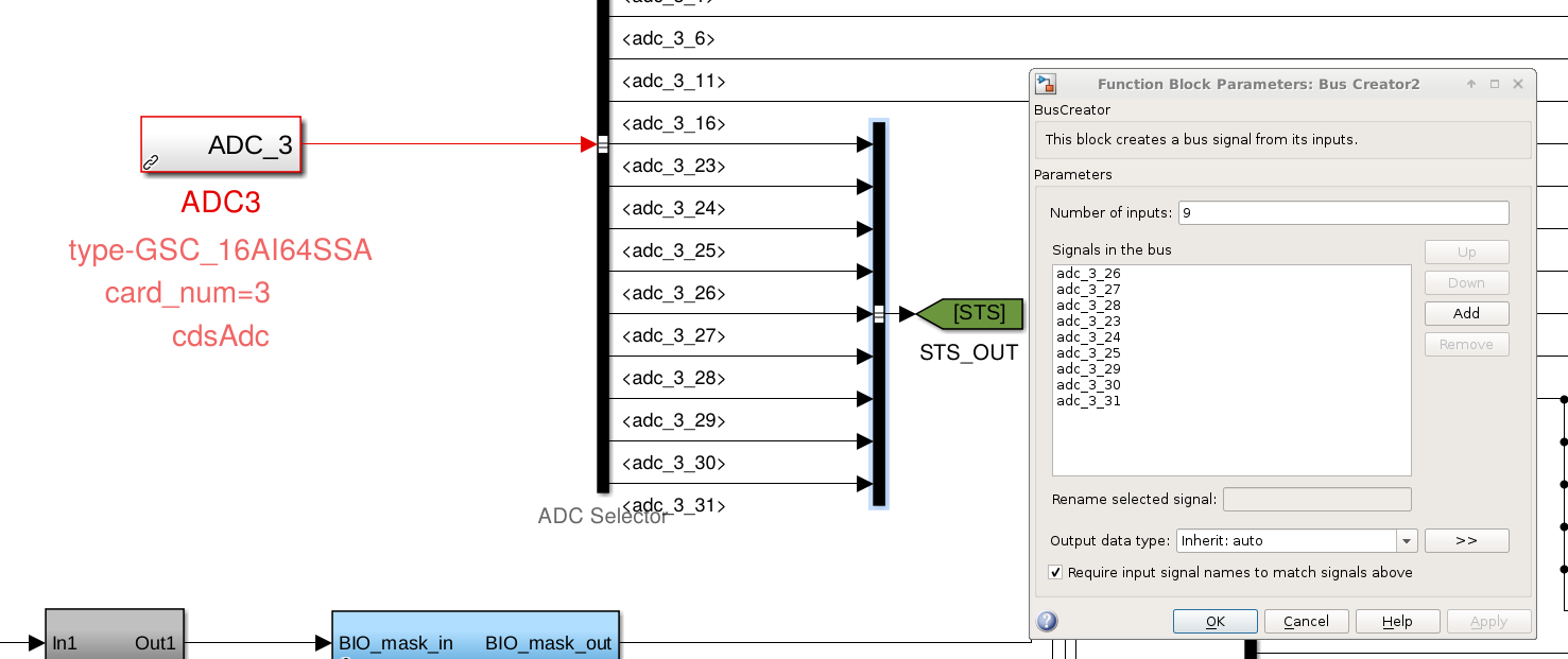
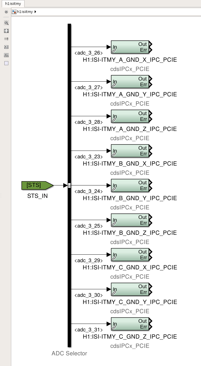
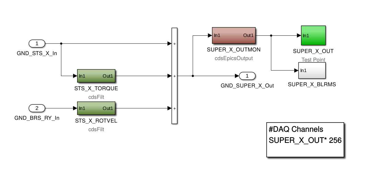
J. Kissel, H. Radkins, J. Warner Problems appear to arise from a factor 2.0 error in the sensor correction system to the ITM ISIs. Actively under investigation. Band-aid solution for now is to turn down the calibration of the ITMY STS for the entire corner by 0.5 via the STS selection matrix elements in H1:ISI-GND_STS_MTRX channels. It looks to be a problem with the newly installed super sensor generation in the corner (ISI_GND_SENSCOR_ITMX or ISI_GND_SENSCOR_ITMY) which only affects the X and Y DOFs. As we know and have begun to hate, all new filters get started in the front end as input ON, output ON, and a gain of 1. THIS SUCKS. Since LHO has no corner station BRSs, we want any correction paths to be OFF. However, the TORQUE correction path for the STS was ON as a direct pass through, and thus doubling the signal. As soon as I post this aLOG, Hugh and I will rip off the bandaid solution, and make the real fix. Unrelated confusing, but inconsequential error: STS mapping of the three corner station STSs on the way to the new seiproc model might be screwed up. See attached images. According to D0901301, the third card, ADC3, in the h1 isiitmy I/O chassis receives the STSs in the following order: Location Physical Nickname Electronics Name ADC Channels for BSC1 aka ITMY (the blue text in the drawing) HAM2 HAM2 STS A X 23 Y 24 Z 25 Beer Garden ITMY STS B X 26 Y 27 Z 28 HAM5 HAM5 STS C X 29 Y 30 Z 31 And this is the order in which the ADC selector attached to the ADC3 part in the h1isiitmy model is broadcasting the signals. However, the *bus creator* that receives and concatenates these signals into a tag *incorrectly* labels things in a different, labeling 23-25 (STSA/HAM2) to "26-28 (STSB/ITMY)", 26-28 (STSB/ITMY) to "23-25 (STSA/HAM2)", and leaves 29-31 (STSC/HAM5) correct. Thankfully, at the other end of the tag, the bus selector -- retaining this incorrect order -- maps the signals to IPC connections that are in the end, still correct, such that STSA/HAM2 gets broadcast as STSA, and STSB/ITMY gets broadcast as STSB. We should fix this, but *phew*.
First image is the offending doubling in the "BRS" area. The STS_X_TORQUE filter path was ON as JK says but with no filters so passing through and doubling the SUPER_X(Y)_OUT.
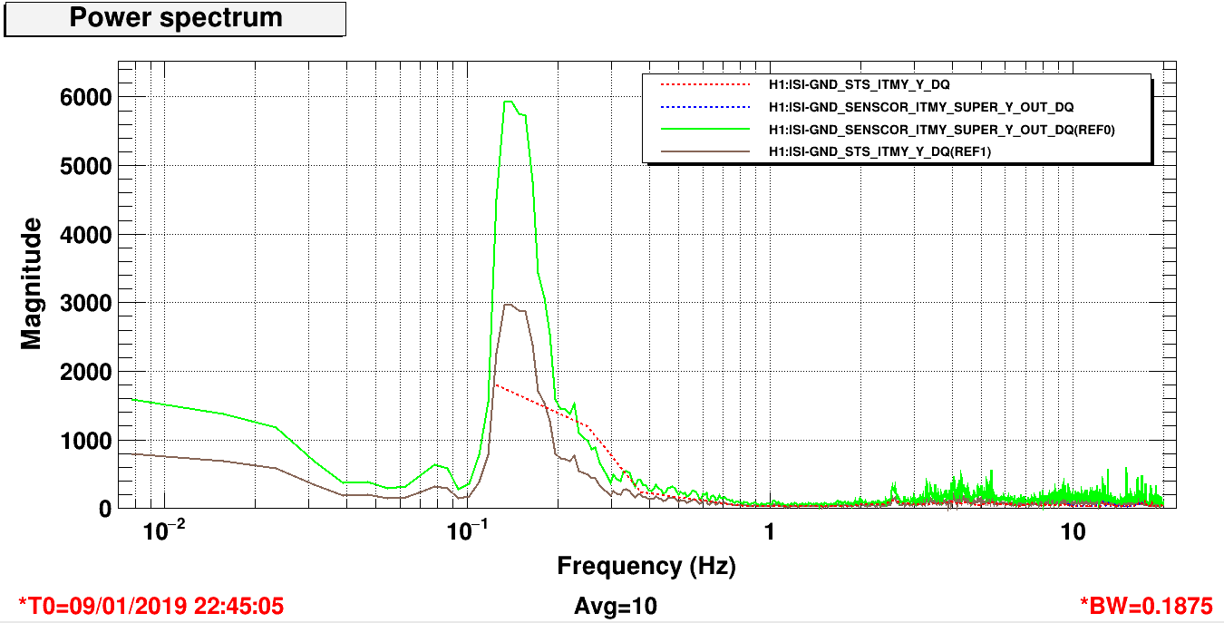
After correcting this by ramping the TORQUE gain to zero and the selection matrix gain (e.g. H1:ISI-GND_STS_MTRX_1_4) back to 1, the signals look back to correct--see second attachment:
The solid references are from hours ago and the 2x is evident comparing the ground STS to the SENSCOR SUPER OUT. The current dashed traces have those signal now just overlapping (reduced BW-sorry) and the same as the earlier GND signal.
Will attach attack SDF now for posterity. SDF values updated.
Chandra R., Gerardo M., Kyle R.
Today we removed the existing (iLIGO, circa 1998) 2500 l/s ion pump and replaced it with another iLIGO one which had been rebuilt. GV14 and GV15 were hard-closed throughout the day to facilitate this.
This exercise provided an interesting data point. The pristinely baked, dry etc... new ion pump internals/interior, though having been vented with dry N2 this morning to prepare it for installation, was, in fact, exposed to the higher-than-normal moist air (raining today) for a few hours while the pump exchanging was taking place. This exposing is required and purging while being exposed for this short time frame isn't typically needed. However, today, upon pumping back down, starting the pump and combining it with the X-mid volume, I was surprised at how "wet" the resulting pump had become as a result of this brief room-air exposure. The resulting pressure was abnormally high and I was hesitant to expose X1 and X2 to this water load. The interesting part is how rapidly this "water source" was depleted. What this shows is that the water accumulation on the vacuum baked surfaces while exposed to the wet room air hadn't had enough time to permeate deeply into the surface and was, thus, easily and mostly removed in a short time period upon re-exposure to vacuum - fascinating!
The pristine pump was vented yesterday afternoon (with bottled UHP N2) and bolts removed from its blank to save time today.
Serial number 70035 was removed and replaced by serial number 70105
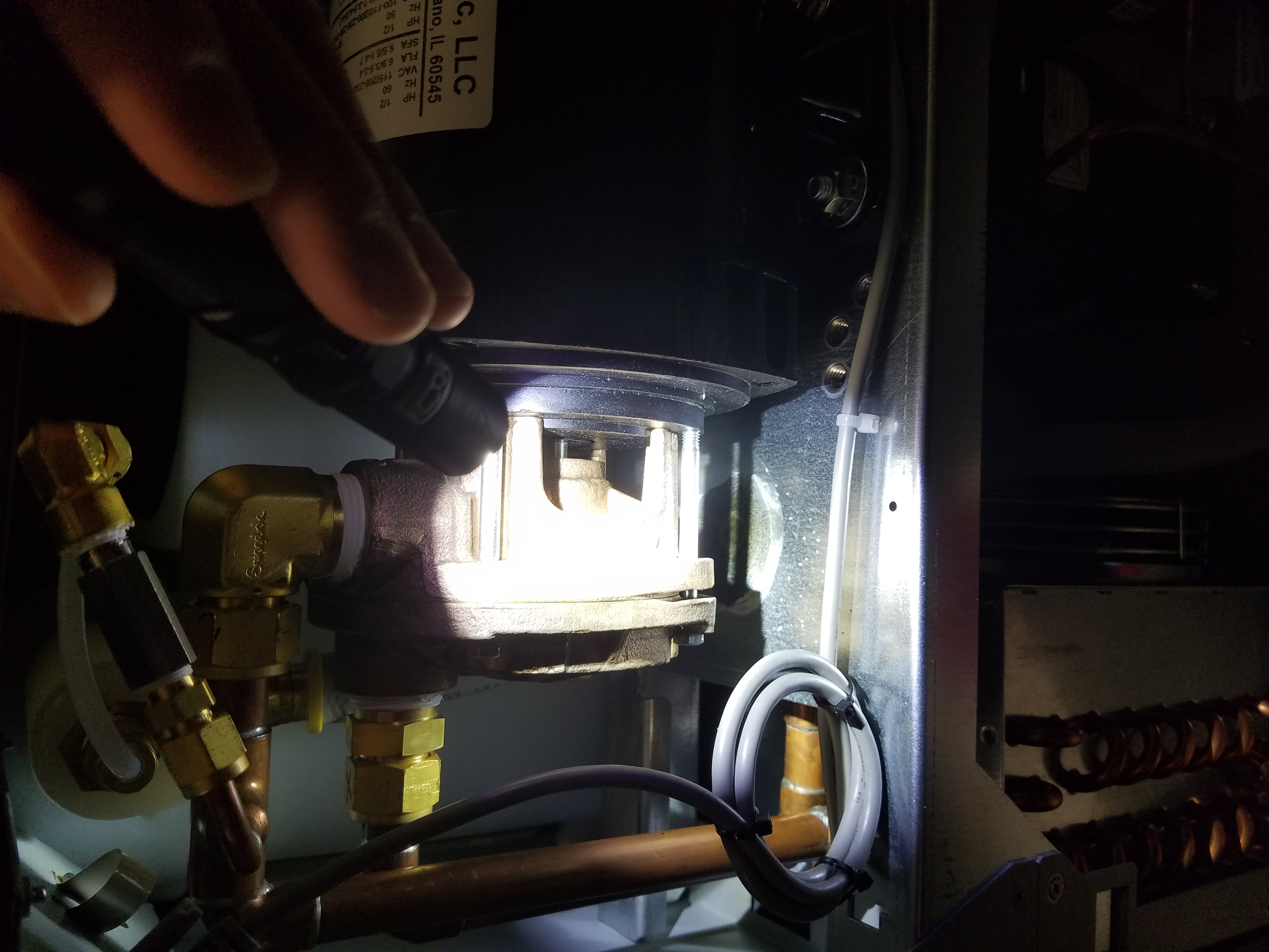
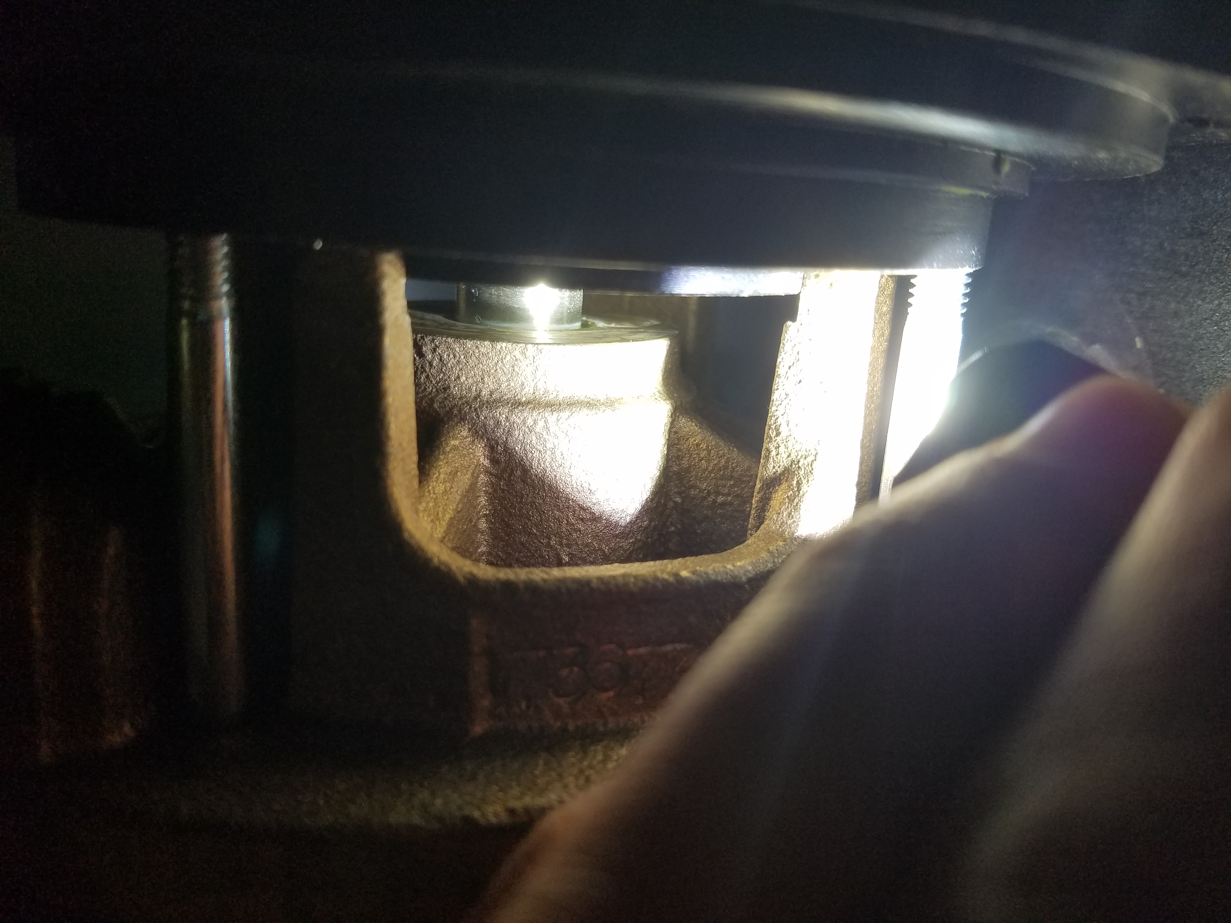
TVo and I went on a leak hunt and went through the table, lines, and then opened the chiller. Opening chiller revealed a puddle under the pump (see attached picture). It looks like we have a leaky pump shaft seal. Filed WP8036 and went to swap the chiller with the spare. The spare chiller would give us a "Low Fixed Pressure" warning and would then shut down. The low threshold was set to 3.0psi and when starting the chiller it would only read around 1.4psi. No flow was ever observed while we tried to turn this on. We eventually gave up and swapped the leaky one back in.
Back in April, Greg Grabeel fixed what is currently our spare from an issue that seems to be exactly the same (alog41314). He ran the chiller in a closed loop for a week back then, so I imagine that it should work now as well. Perhaps the issue we had today was just operator error. We will look into getting parts to fix the leaky seal, and how to get the spare running again.
In an attempt to troubleshoot the spare chiller, I set it up in a closed loop and switched it on. The chiller started right up without issue and ran for ~15min without any signs of leaks.
I can't think of anything I did differently, so my current theory is that there was an air bubble trapped in an odd place. We can swap this out next Tuesday.
Helium leak tested nipple-to-GV 16.5" joint as well as nipple welds with background of 2 x 10⁻⁹ torr*L/sec -> OK. Currently there is a zero-length reducer with a 1 1/2" valve installed in place of the nominal 2500 L/sec ion pump which has been removed and is being refurbished.
Leak testing related to install from aLOG 41523
Baffle nipple/housing is SN006. Chevron baffle assembly is SN004.