Following up on alog 46240, we made the following mods to the ISS Second Loop, S/N S1700062, which is now installed again (PCB D1600298):
To account for the increased analog gain we reduced the VGA gain to 0dB (from +20dB). We increased the REFERENCE_IN_MTRX_1_2 gain to 10 (from 1) and the REFERENCE_IN_MTRX_1_4 gain to 0.5 (from 0.05). The reference offset was also adjusted to 537 (from -35.14). At first glance, the output offset fluctuations are significantly reduced.
H1:PSL-ISS_SECONDLOOP_REFERENCE_IN_MTRX_1_4 is controlled by IMC_LOCK guardian, so a factor of 10 was put into that (i.e. 0.5 from 0.05 for AC coupled, and 50 from 5 for DC coupled 30W).
Also we noticed that 10Hz pole on/off indicator for 3rd loop and slow offset path on the front panel was not working (it never turned on), but the readback was working and the pole seemed to be switching.
[PatrickT, Jenne]
We've struggled to keep Yarm ALS locked this morning since we have particularly bad ground motion today. We started down a path of trying to figure out why.
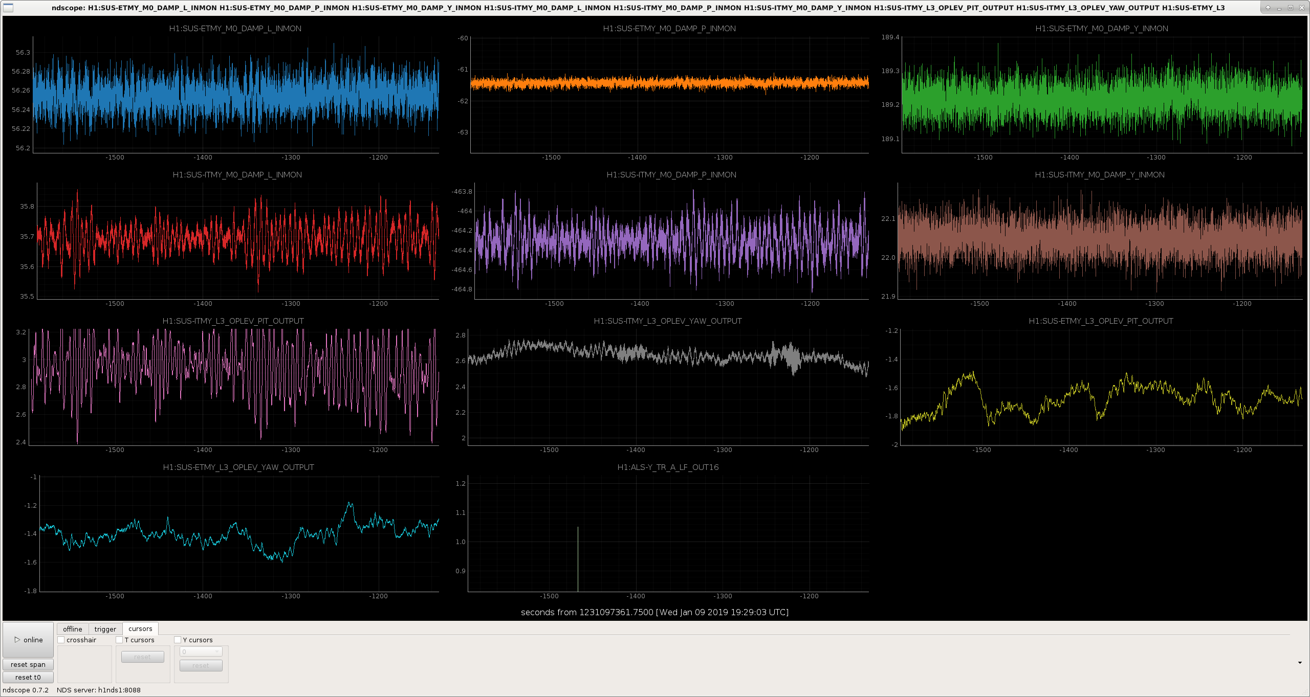
The Yarm SUSPOINT length projection from the seismic tables doesn't seem very coherent with the power fluctuations in the Yarm. This led us to look at the angular motion of the optics.
In the attached ndscope figure, you can see that the oplevs for ITMY and ETMY, pitch and yaw are on the same y-axis range of 0.8 urad. However, ITMY pit is moving more than this scale. (Stefan has some plots up that show that a similar phenomenon is happening on the Xarm).
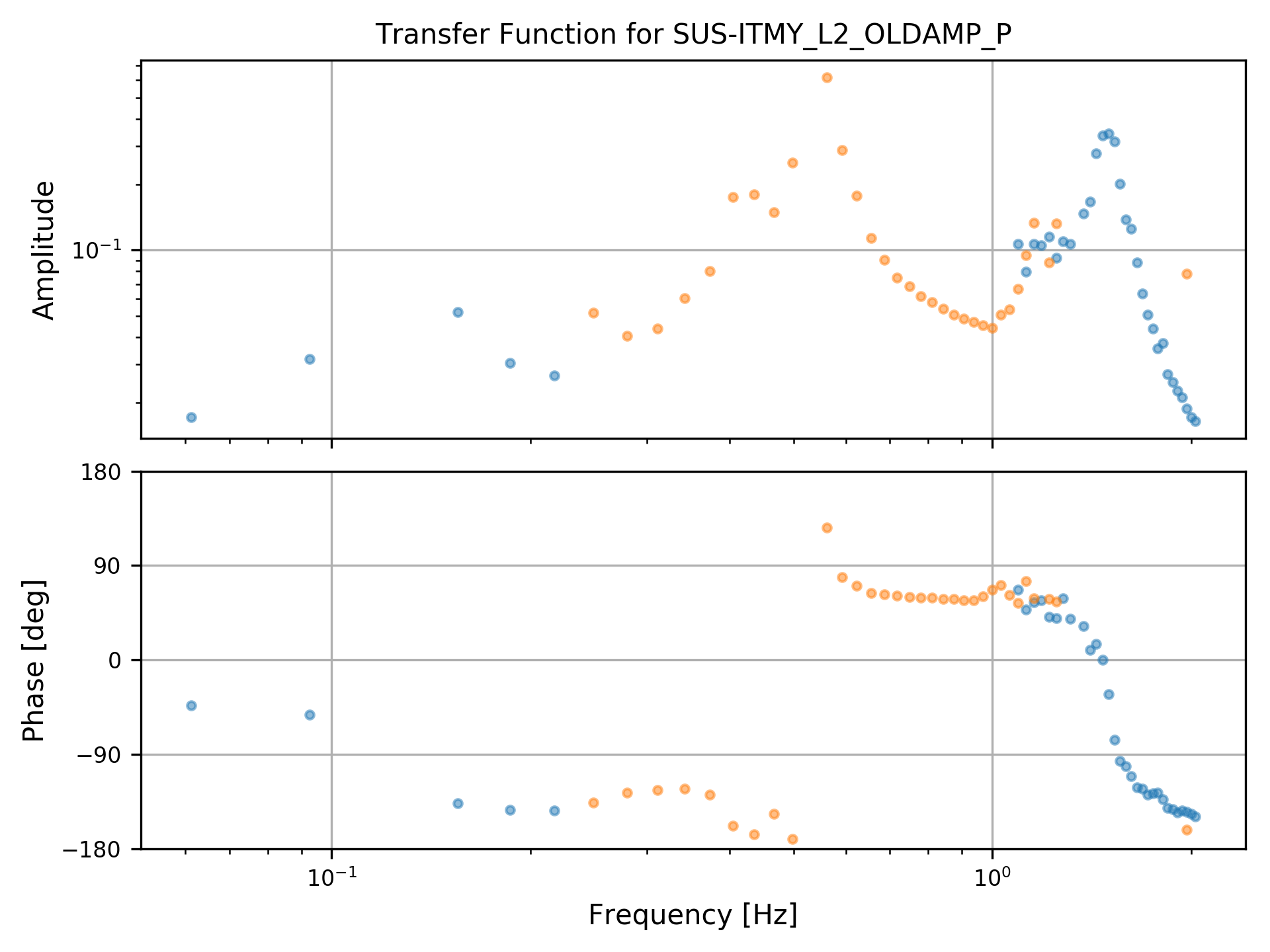
We took a measurement of the ITMY pit oplev loop, with a thought toward using the oplev to damp this motion. However, before we go further down this path, we're looking with Sheila and Stefan if there are any inconsistencies in the seismic isolation or suspension top stage damping that may have potentially come in during some maintenance or computer reboot time.
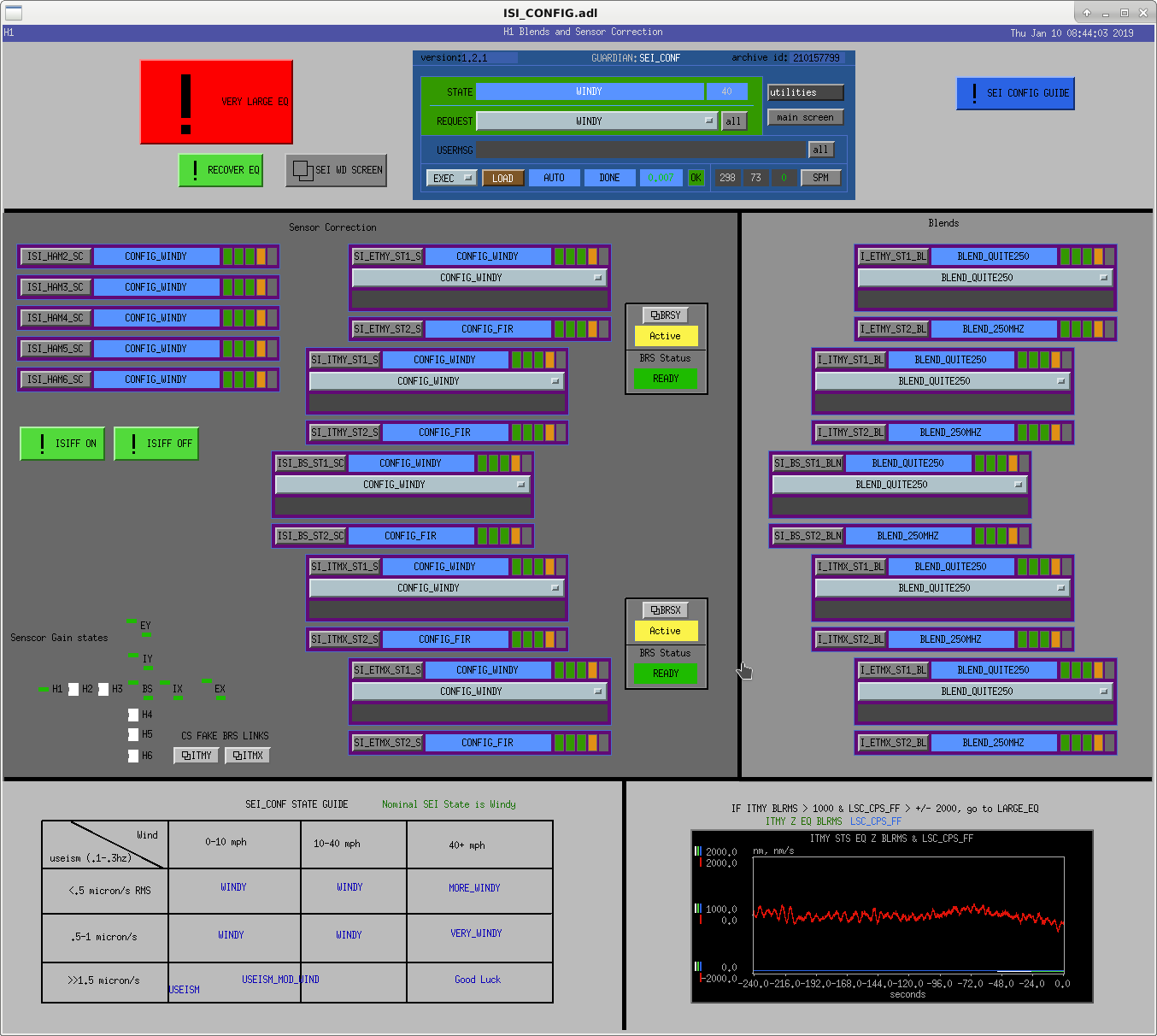
I've added links to BRS overviews for the non-existent CS BRS to the ISI-CONFIG screen so we have an easy way to check the status of these paths in the future. They're in the bottom left quarter of the screen, above the configuration guide. I had to modify the ITMX/Y bsc-isi macros to get them to work, which breaks Hugh's clever "Not Built" labels on the ISI overviews.
*This comment is a follow up to the comments below. Why is this post appearing above the earlier comments? It makes no sense out of order...*
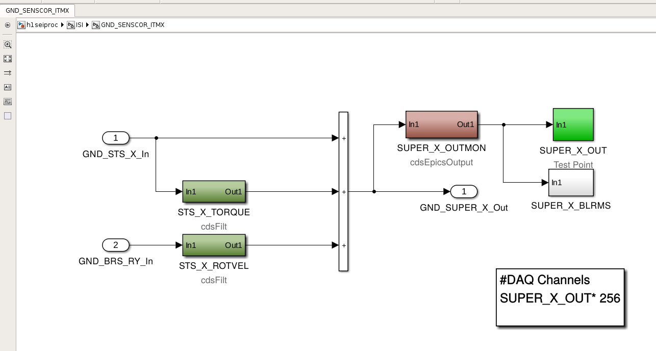
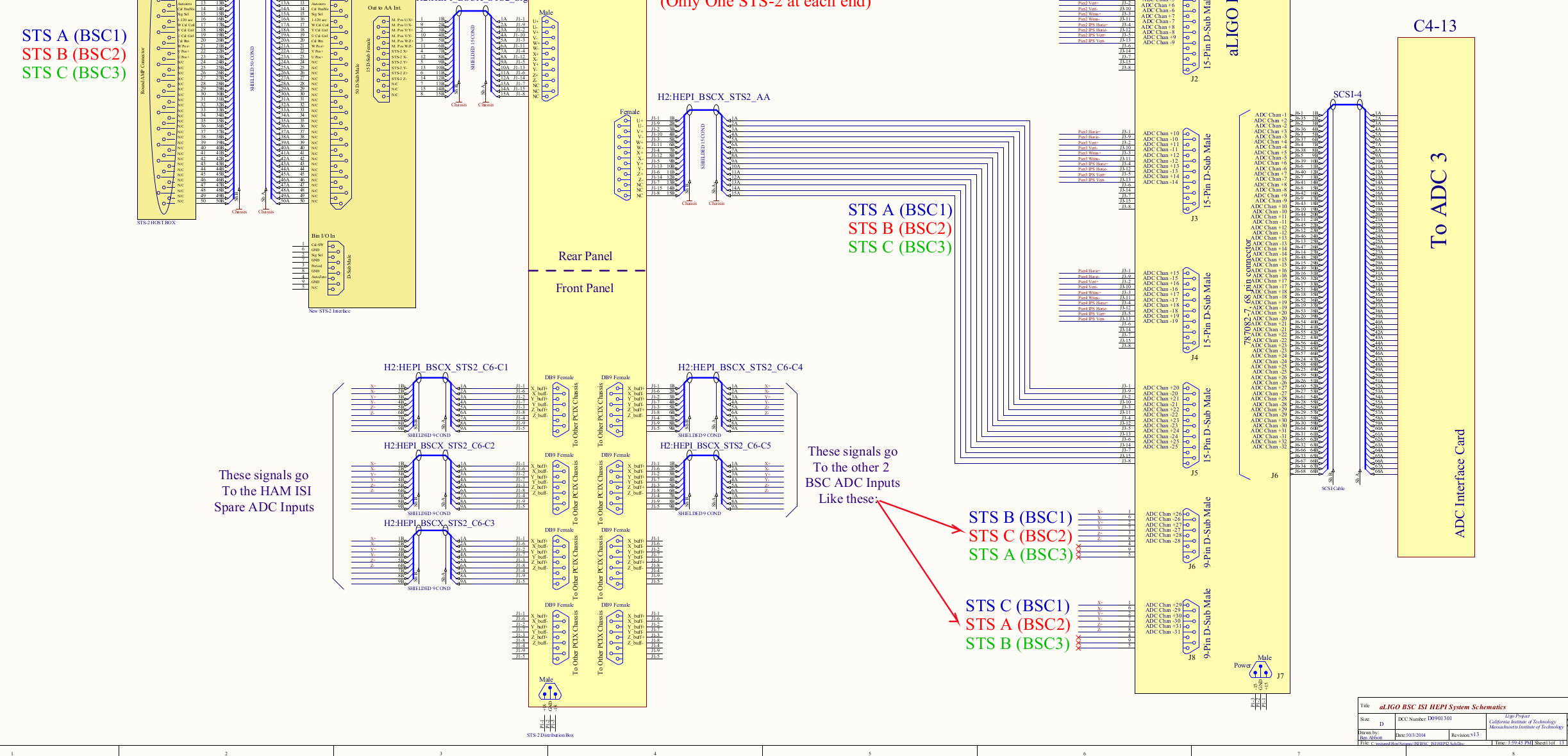
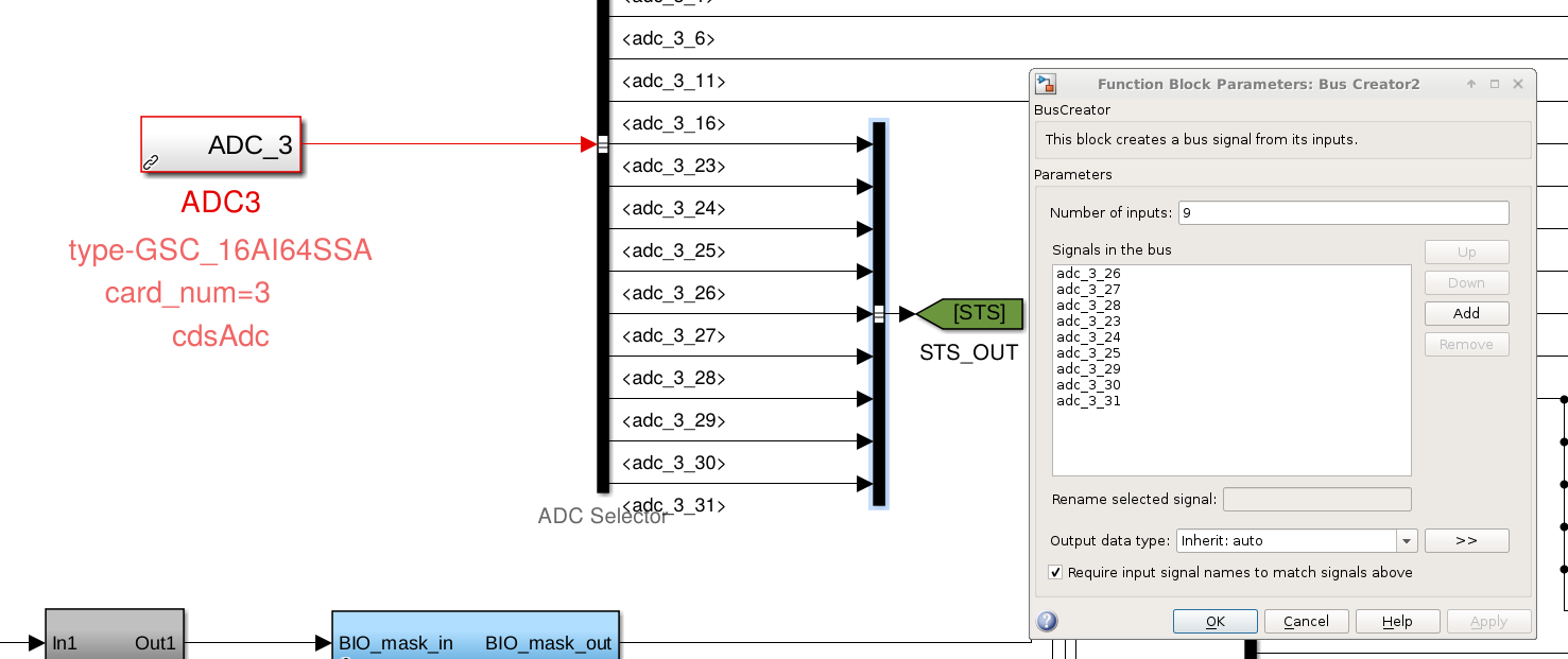
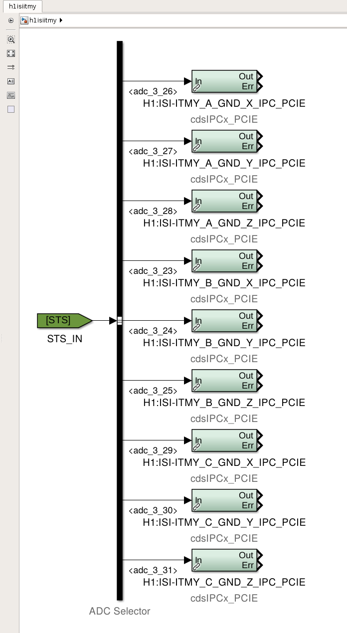
J. Kissel, H. Radkins, J. Warner Problems appear to arise from a factor 2.0 error in the sensor correction system to the ITM ISIs. Actively under investigation. Band-aid solution for now is to turn down the calibration of the ITMY STS for the entire corner by 0.5 via the STS selection matrix elements in H1:ISI-GND_STS_MTRX channels. It looks to be a problem with the newly installed super sensor generation in the corner (ISI_GND_SENSCOR_ITMX or ISI_GND_SENSCOR_ITMY) which only affects the X and Y DOFs. As we know and have begun to hate, all new filters get started in the front end as input ON, output ON, and a gain of 1. THIS SUCKS. Since LHO has no corner station BRSs, we want any correction paths to be OFF. However, the TORQUE correction path for the STS was ON as a direct pass through, and thus doubling the signal. As soon as I post this aLOG, Hugh and I will rip off the bandaid solution, and make the real fix. Unrelated confusing, but inconsequential error: STS mapping of the three corner station STSs on the way to the new seiproc model might be screwed up. See attached images. According to D0901301, the third card, ADC3, in the h1 isiitmy I/O chassis receives the STSs in the following order: Location Physical Nickname Electronics Name ADC Channels for BSC1 aka ITMY (the blue text in the drawing) HAM2 HAM2 STS A X 23 Y 24 Z 25 Beer Garden ITMY STS B X 26 Y 27 Z 28 HAM5 HAM5 STS C X 29 Y 30 Z 31 And this is the order in which the ADC selector attached to the ADC3 part in the h1isiitmy model is broadcasting the signals. However, the *bus creator* that receives and concatenates these signals into a tag *incorrectly* labels things in a different, labeling 23-25 (STSA/HAM2) to "26-28 (STSB/ITMY)", 26-28 (STSB/ITMY) to "23-25 (STSA/HAM2)", and leaves 29-31 (STSC/HAM5) correct. Thankfully, at the other end of the tag, the bus selector -- retaining this incorrect order -- maps the signals to IPC connections that are in the end, still correct, such that STSA/HAM2 gets broadcast as STSA, and STSB/ITMY gets broadcast as STSB. We should fix this, but *phew*.
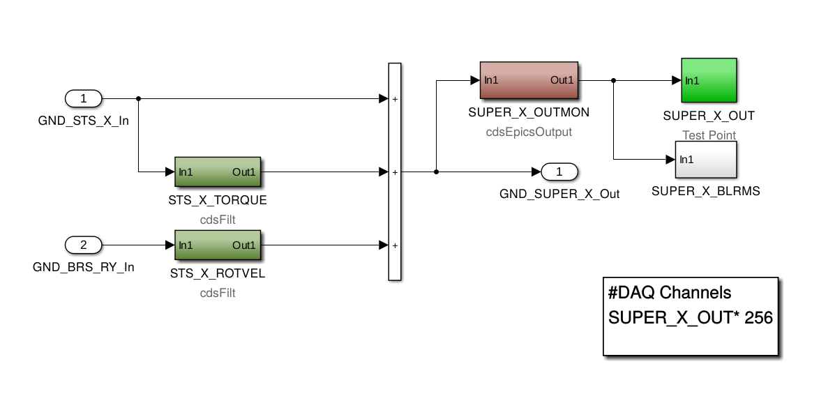
First image is the offending doubling in the "BRS" area. The STS_X_TORQUE filter path was ON as JK says but with no filters so passing through and doubling the SUPER_X(Y)_OUT.
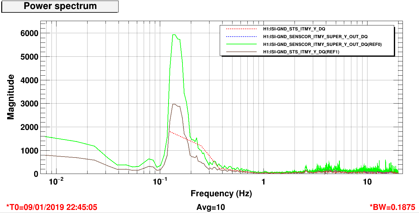
After correcting this by ramping the TORQUE gain to zero and the selection matrix gain (e.g. H1:ISI-GND_STS_MTRX_1_4) back to 1, the signals look back to correct--see second attachment:
The solid references are from hours ago and the 2x is evident comparing the ground STS to the SENSCOR SUPER OUT. The current dashed traces have those signal now just overlapping (reduced BW-sorry) and the same as the earlier GND signal.
Will attach attack SDF now for posterity. SDF values updated.
Dick Gustafson, Marc Pirello
Today, we investigated the output of 8 Port RF Amplifiers. We looked at 45MHz, 24MHz, 71MHz at the PSL racks, and 9MHz in the CER. All ports have good signal with very little noise. We also looked at the 10MHz signal in the CER which is derived from the 80MHz VCO in the CER. This signal has a few harmonics which can be low pass filtered out. Attached are the plots for each test, including the before and after for the 10MHz test. The 71MHz signal also has a bump near the 80MHz which looks to be coupled from somewhere. This signal may also benefit from a filter.
*edit: fixed some mislabeled plots
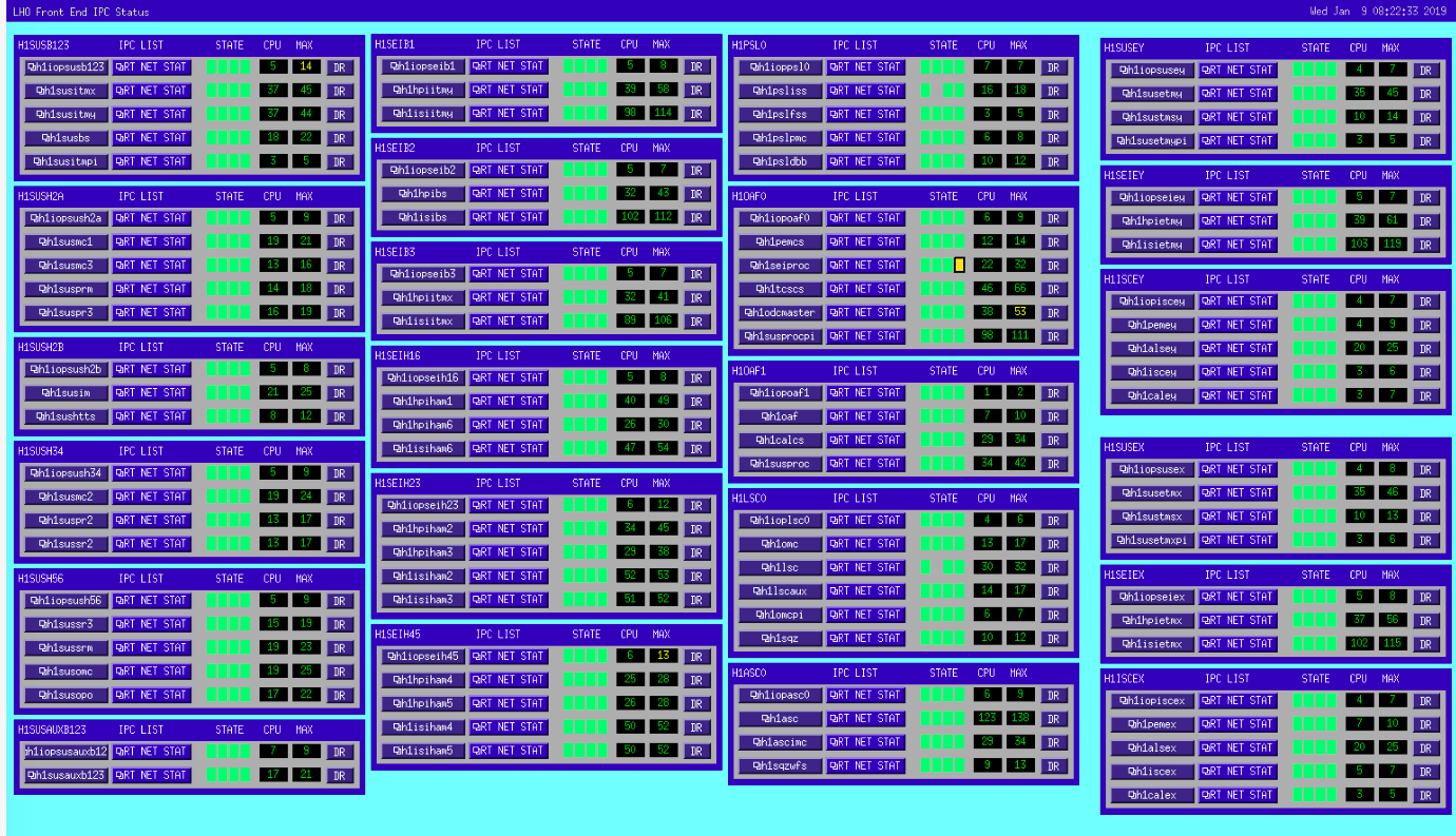
Following yesterday's Dolphin upgrade, we have seen no Dolphin IPC errors overnight. The IPC MEDM (see attached) shows a single long-range error at Jan 08 2019 18:02:27 PST from EY to h1seiproc.
Checking dust monitors for possible problems over a period of 12 hours ending 0 hours ago...
*H1:PEM-CS_DUST_LVEA6 WARNING: dust counts did not change, please investigate
H1:PEM-CS_DUST_LVEA10 OK
H1:PEM-CS_DUST_PSL101 OK
*H1:PEM-CS_DUST_PSL102 WARNING: dust counts did not change, please investigate
H1:PEM-CS_DUST_DR1 OK
H1:PEM-CS_DUST_LAB1 OK
H1:PEM-CS_DUST_LAB2 OK
H1:PEM-EX_DUST_VEA1 OK
H1:PEM-EY_DUST_VEA1 OK
According to their medm screens, H1:PEM-CS_DUST_LVEA6 and H1:PEM-CS_DUST_PSL102 do not appear to be running.
We had a long maintenance day today, 46295. Here are some steps that we took to get through initial alignment and the first few steps of locking. We finished the basic maintenance recovery around 8 pm, but we have been having difficulty locking, probably because of the ground motion since.
Further difficulties locking.
Dolphin diagnostics differences before/after today's EEPROM change (left chevron after, right chevron before)
< Date : Tue Jan 8 13:24:38 PST 2019
> Date : Tue Jan 8 09:43:36 PST 2019
< EEPROM version : 97
> EEPROM version : 08
< EEPROM development ver : 1
< Topology Autodetect : No
> Topology Autodetect : Yes
< PCIe slot state : x8, Gen1 (2.5 GT/s)
> PCIe slot state : x8, Gen2 (5 GT/s)
< Link 0 uptime : 11585 seconds
> Link 0 uptime : 4218828 seconds
< Link 0 state : x8, Gen1 (2.5 GT/s)
< Link 0 required : x8, Gen1 (2.5 GT/s)
< Link 0 capabilities : x8, Gen1 (2.5 GT/s)
> Link 0 state : x8, Gen2 (5 GT/s)
> Link 0 required : x8, Gen2 (5 GT/s)
> Link 0 capabilities : x8, Gen2 (5 GT/s)
< [WARN] IXH Adapter 0 - PCIe slot link speed is only Gen1
< ==> Local adapter 0 has 1 warnings.
As requested by Chandra, I have increased the upper alarm level for the beam tube vacuum gauges at MX from 5.0e-09 to 2.0e-08 Torr and restarted the alarm system.
-<Channel name="H0:VAC-MX_X1_PT343B_PRESS_TORR" low="1.0e-10" high="5.0e-09" description="VE gauge, MX X1-beamtube, CC">
+<Channel name="H0:VAC-MX_X1_PT343B_PRESS_TORR" low="1.0e-10" high="2.0e-08" description="VE gauge, MX X1-beamtube, CC">
-<Channel name="H0:VAC-MX_X5_PT346B_PRESS_TORR" low="1.0e-10" high="5.0e-09" description="VE gauge, MX X2-beamtube, CC">
+<Channel name="H0:VAC-MX_X5_PT346B_PRESS_TORR" low="1.0e-10" high="2.0e-08" description="VE gauge, MX X2-beamtube, CC">
TITLE: 01/09 Day Shift: 16:00-00:00 UTC (08:00-16:00 PST), all times posted in UTC
STATE of H1: Commissioning
INCOMING OPERATOR: None
SHIFT SUMMARY:
LOG:
Chandra R., Gerardo M., Kyle R.
Today we removed the existing (iLIGO, circa 1998) 2500 l/s ion pump and replaced it with another iLIGO one which had been rebuilt. GV14 and GV15 were hard-closed throughout the day to facilitate this.
This exercise provided an interesting data point. The pristinely baked, dry etc... new ion pump internals/interior, though having been vented with dry N2 this morning to prepare it for installation, was, in fact, exposed to the higher-than-normal moist air (raining today) for a few hours while the pump exchanging was taking place. This exposing is required and purging while being exposed for this short time frame isn't typically needed. However, today, upon pumping back down, starting the pump and combining it with the X-mid volume, I was surprised at how "wet" the resulting pump had become as a result of this brief room-air exposure. The resulting pressure was abnormally high and I was hesitant to expose X1 and X2 to this water load. The interesting part is how rapidly this "water source" was depleted. What this shows is that the water accumulation on the vacuum baked surfaces while exposed to the wet room air hadn't had enough time to permeate deeply into the surface and was, thus, easily and mostly removed in a short time period upon re-exposure to vacuum - fascinating!
The pristine pump was vented yesterday afternoon (with bottled UHP N2) and bolts removed from its blank to save time today.
Serial number 70035 was removed and replaced by serial number 70105
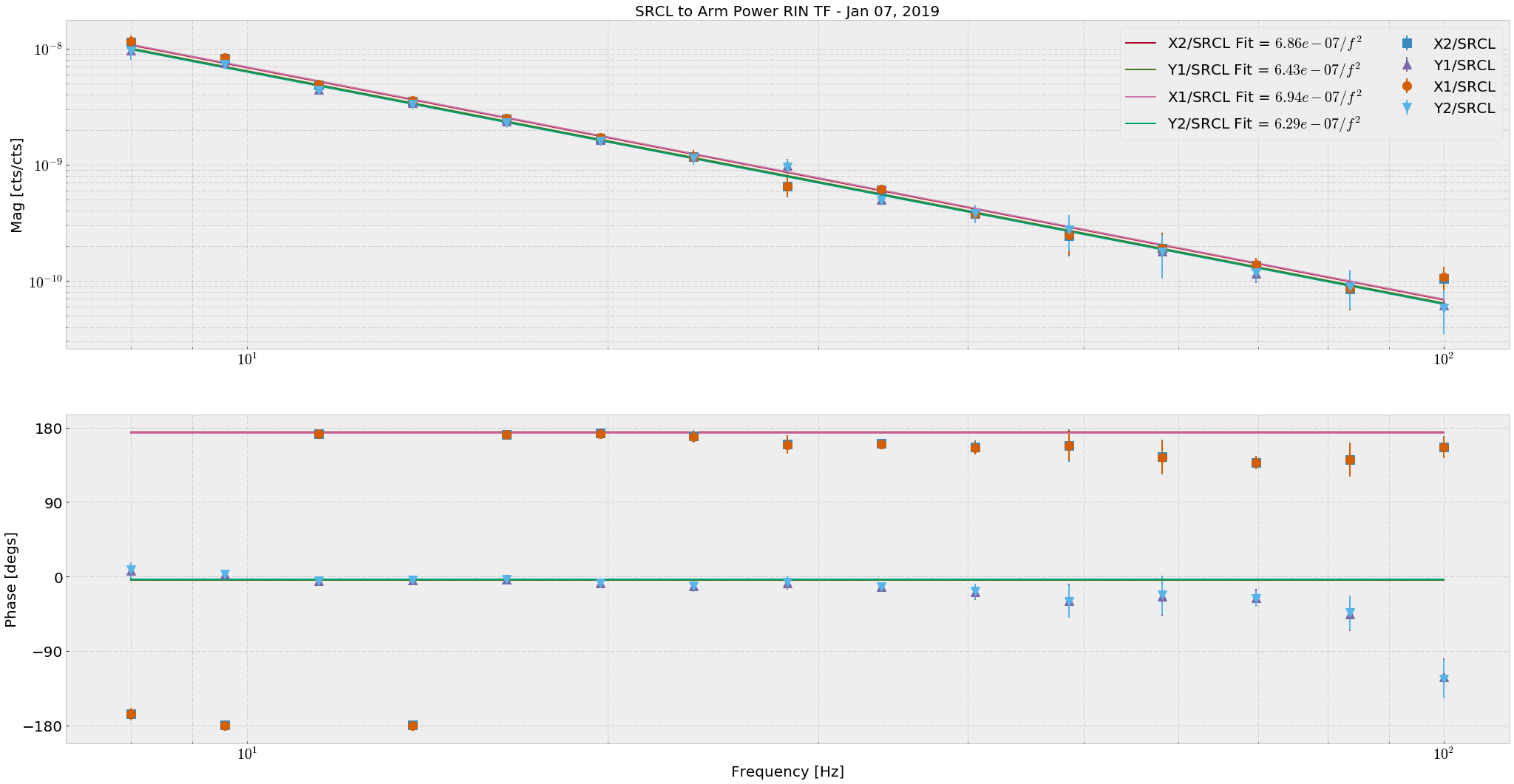
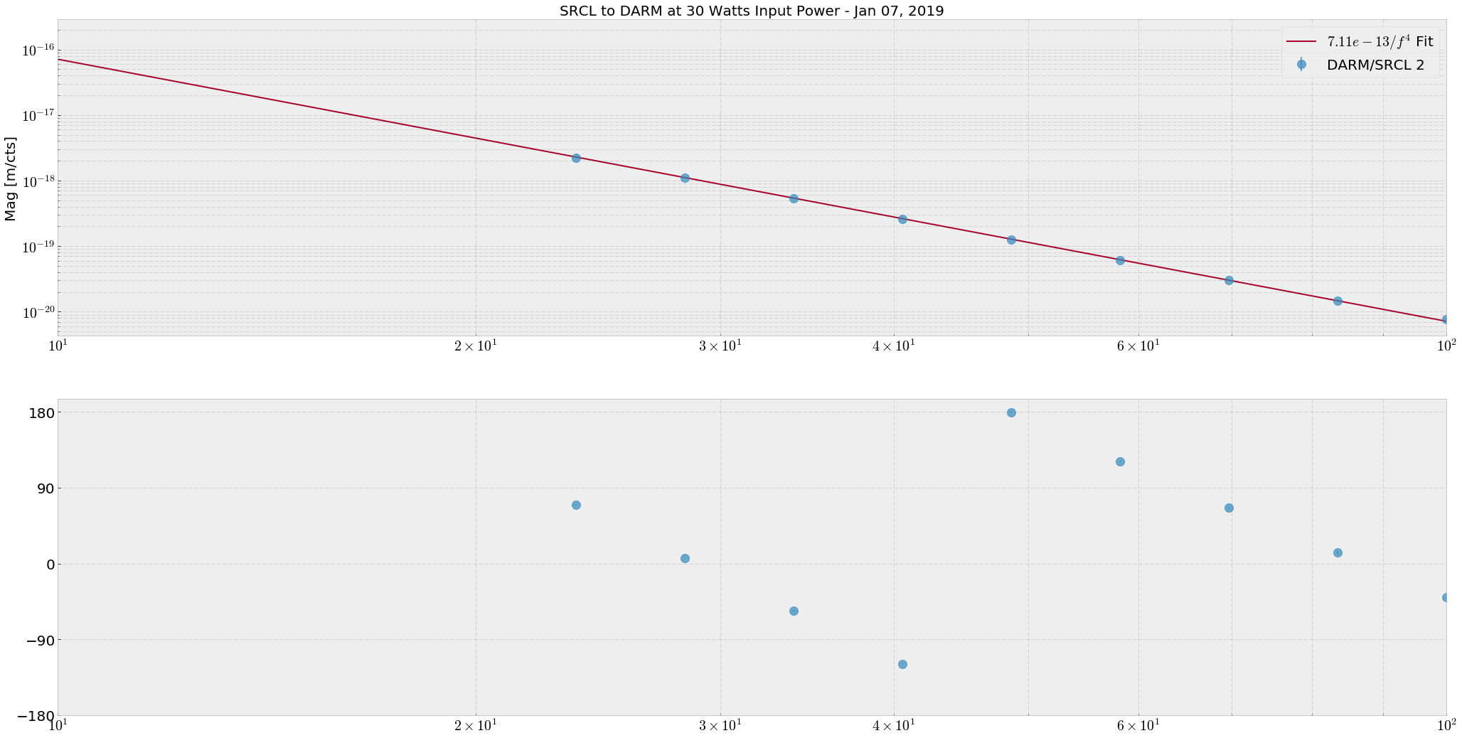
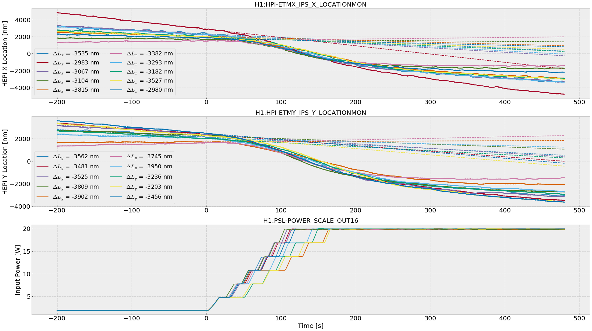
For 30 watts of input power:Arm Power = 127.2 +- 5.4 kWSRCL Dither to Arm Power Measurement: Long ago, Peter F came to Hanford and asked me to measure the arm power by moving the SRM. The idea is to use the SRCL dither to cause the arm power to fluctuate differentially. When the arm power fluctuates differentially, arm radiation pressure couples to DARM. I measured the TF from SRCL to arm power transmissions RIN and SRCL to DARM at 30 watts of input power and 43 power recycling gain and SRCL feedforward off. (Had to divide the DARM calibration by two because our DARM is calibrated such that LDARM = Lx - Ly, but I assumed LDARM = (Lx - Ly)/2. This was particularly hard to find.) I then fit some constants α1 and α2 to the TFs: α2/f^2 to the SRCL_ctrl/ArmPowerTransRIN measurements and α1/f^4 to the SRCL_ctrl/DARM, and recovered arm power via the equationParm = α1/α2 * π2 * mq * cwhere mq is the mass of the ITMs/ETMs. See the attached PDF for a more exposition to the above equation. In the future we can just take the TF from Arm Power Transmission RIN to DARM. Results:α1 = 7.11 +- 0.07 × 10⁻¹³ (Attachment 2) α2 = 6.6 +- 0.3 × 10⁻⁷ (Attachment 1)From this measurement we can back out an approximate arm power gain. The power in the arms is given by Parm = Pin * gP2 * garm2 / 2 where gP2 ≈ 43 is the power recycling gain and garm2 is the arm power gain. In a perfect, lossless world we would have garm2 = 282. In reality, we have garm2 ≈ 197 EDIT: Gabriele comments that for this low of an arm gain, our losses would have to be incredibly high, on the order of 5000 ppm. EDIT: Stefan asked about the SRCL to Arm RIN fit differences between the arms. There are two QPDs (A and B) at the ends of both arms. Names are like H1:ASC-{X,Y}_TR_{A,B}_NSUM_OUT. These QPD sums are used for monitoring the arm powers. In Attachment 1, I refer to H1:ASC-X_TR_A_NSUM_OUT as X1, H1:ASC-X_TR_B_NSUM_OUT as X2, etc... In the legend, we can see the individual fit values to each ArmTransRIN/SRCL TF to a α2/f2 model. Each of these fits were made with a MCMC and had an uncertainty of around 0.8%QPD/SRCLctrl TFs Model Value X1 X2 Y1 Y2 ---------------------------------------------------------------------------- α2 6.94 × 10⁻⁷ 6.86 × 10⁻⁷ 6.43 × 10⁻⁷ 6.29 × 10⁻⁷We can see that the X1 and X2 fits are close (within 0.6%), and Y1 and Y2 fits are close (within 1%), but the X and Y arm fits together are slightly different (within 4%). Looking at the PDF attached, we can say that the optical response of the Y arm to the SRCL dither γ is less than the optical response of the X arm. ----------------------------------------------------------------------------------------------------------------------------------------------------------------------------------------------------------------- HEPI Offloading Measurement:Results: Change in HEPI offload for each arm during 2 to 20 watt powerup: (see Attachment 3) ΔHEPI_X = -3287 +- 261 nm (or +-8%) ΔHEPI_Y = -3587 +- 246 nm (or +-7%) Change in X Arm Power from 2 to 20 W Input = 95 +- 8 kW Change in Y Arm Power from 2 to 20 W Input = 104 +- 7 kW Total X Arm Power at 20 W = 105 +- 8 kW Total Y Arm Power at 20 W = 115 +- 8 kW Estimated X Arm Power at 30 W = 158 +- 13 kW Estimated Y Arm Power at 30 W = 173 +- 12 kW Arm Power Ratio = Px/Py = 0.9 +- 0.1As a double check of this arm power measurement I have been looking at HEPI offloading of tidal during INCREASE_POWER. When the input power increases from 2 to 20 watts, HEPI moves due to the increase of radiation pressure by about 3000 nanometers in each arm. I fit a simple trend line to capture what the tidal servo was doing anyway, then subtract it at after around 400 seconds when the offload is complete, for 10 separate INCREASE_POWERs. (Attachment 3) We can use these results to estimate the arm powers, assuming all other things being equal in LSC->HEPI tidal offloading, and ΔHEPI_X = ΔLXarm:HEPI Analysis ΔPx = ΔHEPI_X * c/(4 k), where k = DC compliance of the quad TST stage = 2.6 × 10⁻³ m/N. If we trust the measured PRG of ~46 for each of these powerups, that would correspond to an arm gain of gXarm2 ≈ 230 gYarm2 ≈ 250So this measurement reports much higher arm powers, but also a huge mismatch between arms (> 10%). We can learn a lot more about the IFO from this measurement and others like it. The end goal of this is to understand noise couplings to DARM, many of which are governed by these hard to measure numbers like arm power, power recycling gain, signal recycling gain, SRCL detuning and optical spring, DARM offset, coupled cavity poles, etc. If we can make a more complete picture of the IFO, hopefully we will find some things that don't add up. EDITTED for clarity of which measurement gave me which information, added the arm power calculations from HEPI offloading done with Sheila, and added comments from Stefan and Gabriele.
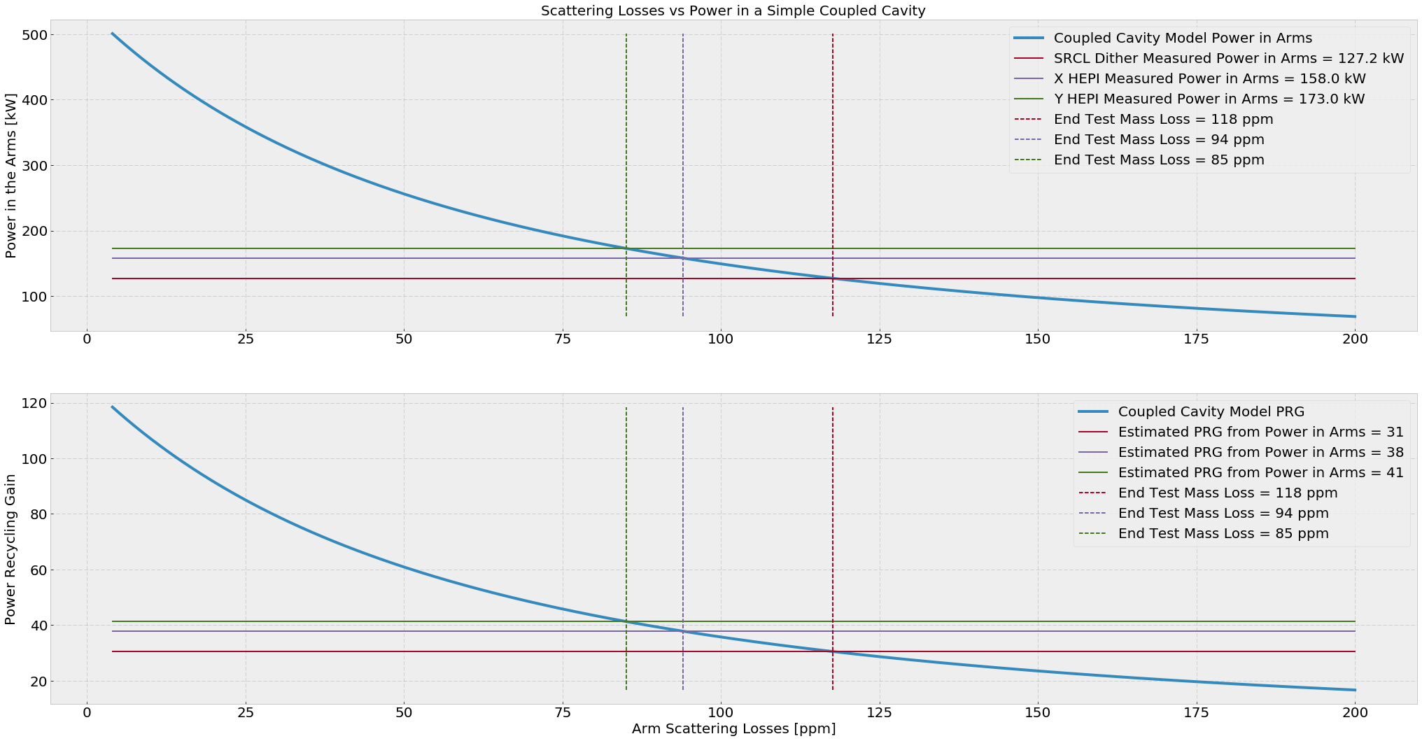
Stefan and I looked at a simple coupled cavity response to arm scattering losses to see what PRGs are consistent with the above arm power levels. We modeled the scattering losses as excess ETM transmission. For the coupled cavity, we foundP_arm = P_in * g_ccArm2 / 2 where g_ccArm = tP tI / (1 + rP rI - rP rE - rI rE) and rP = amplitude reflectivity of the PRM rI = amplitude reflectivity of the ITM rE = amplitude reflectivity of the ETM tP = amplitude transmission of the PRM = sqrt(0.03) tI = amplitude transmission of the ITM = sqrt(0.014) tE = amplitude transmission of the ETM = sqrt(4ppm) (nominal)By varying the ETM transmission from it's nominal 4 ppm, we found arm losses that gave the arm power levels found for 30 watt input above, and then looked at what the PRG would be for that level of losses.Meas Arm Power [kW] Arm Losses [ppm] PRG SRCL dither 127.3 118 31 HEPI X 158. 94 38 HEPI Y 173. 85 41It seems that the SRCL dither measurement arm power is not consistent with the reported PRG of 43 we have at Hanford with 30 watts input.
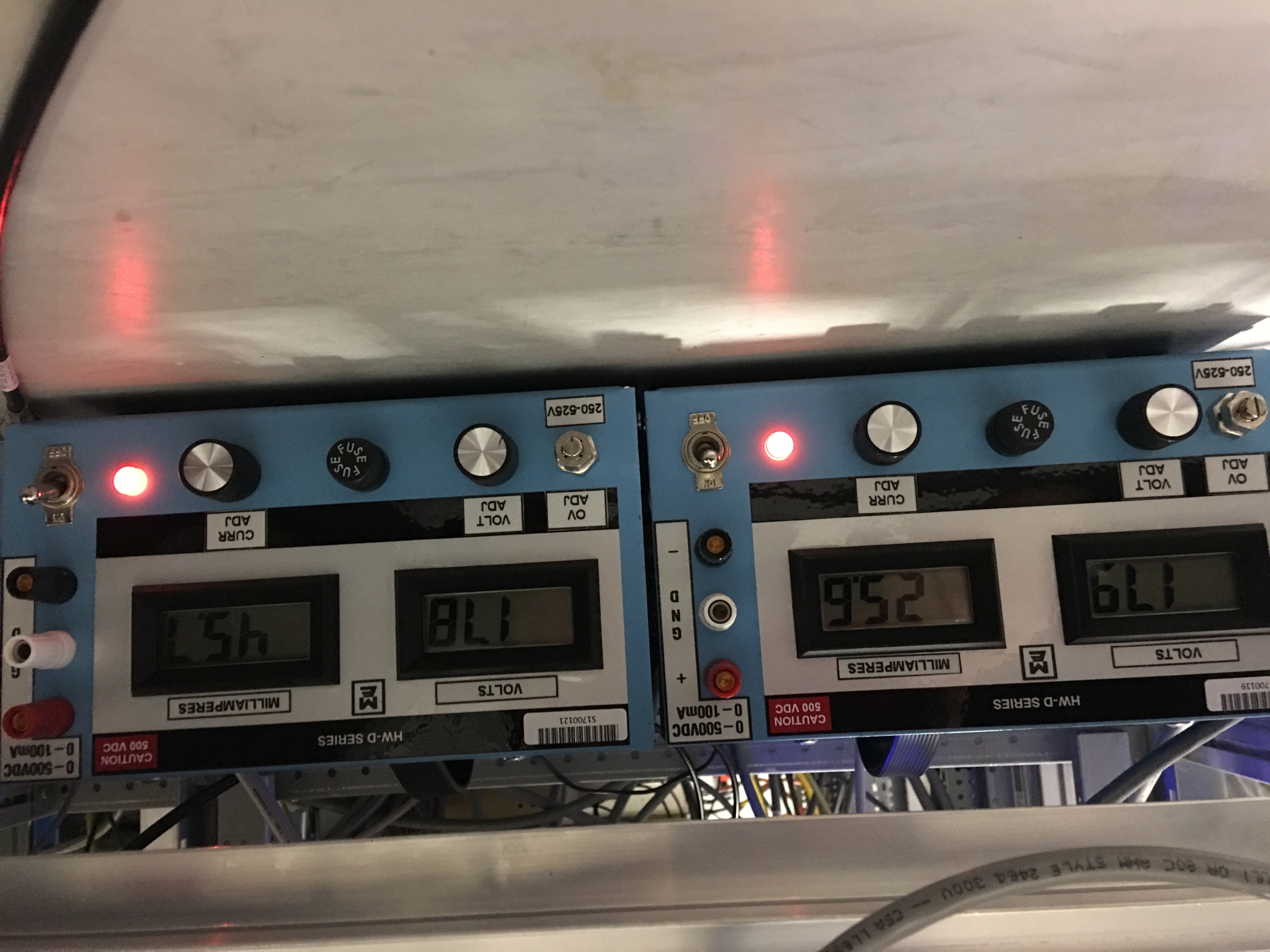
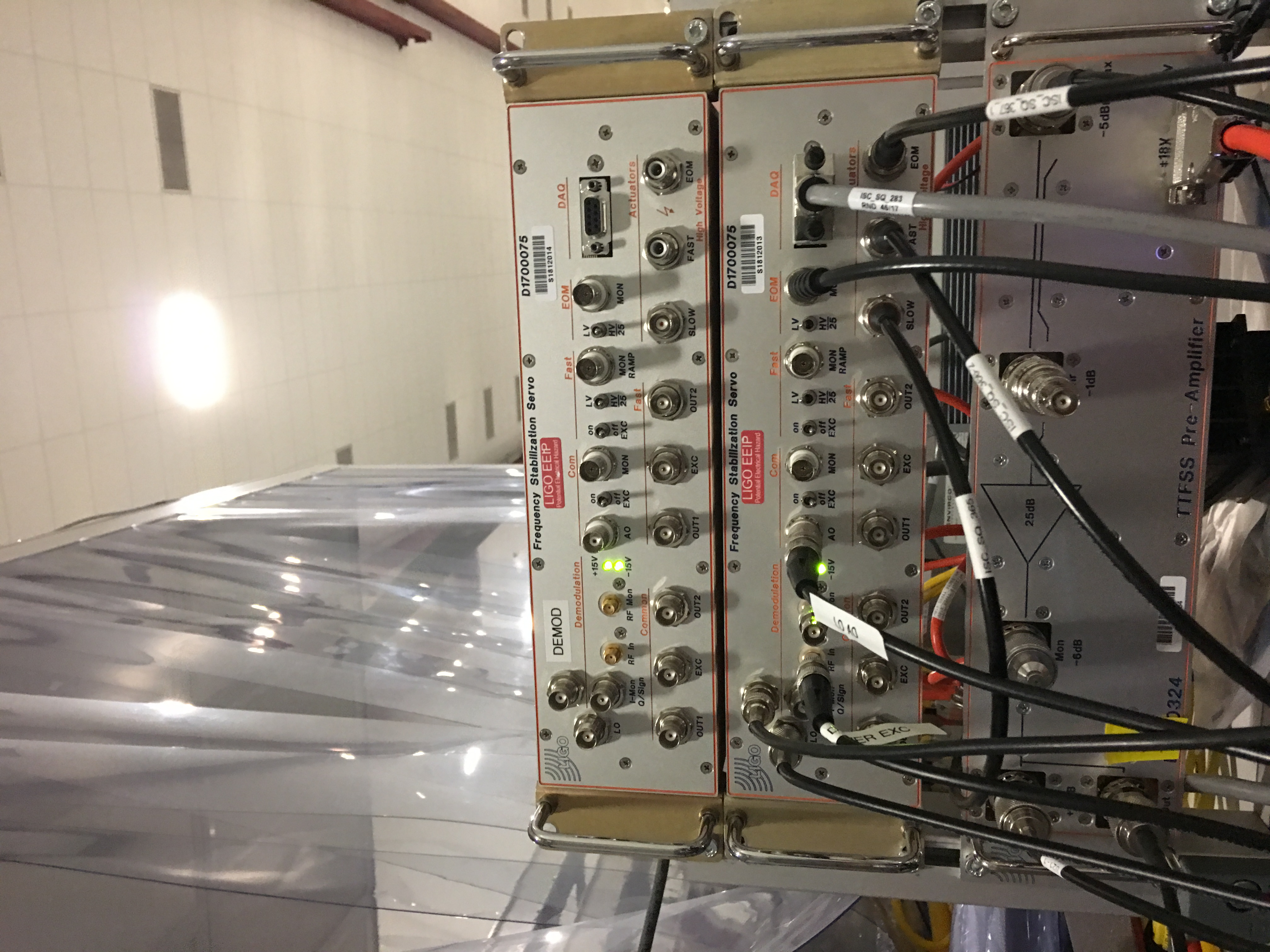
A temporary FSS chassis (S1812014) was installed on ISCT6. I connected the +/- 18VDC to the chassis as well and left it powered that way. The accompanying +/- HV power supplies were placed on the floor inside the squeezer rack and connected to the chassis. The HV supplies were set to 180VDC as per their counterparts in the CER mezzanine and then turned off until they're needed. WP#8029
We need a PFD not a DEMOD for the alternative locking scheme. The bottom unit is already a DEMOD. Will swap.
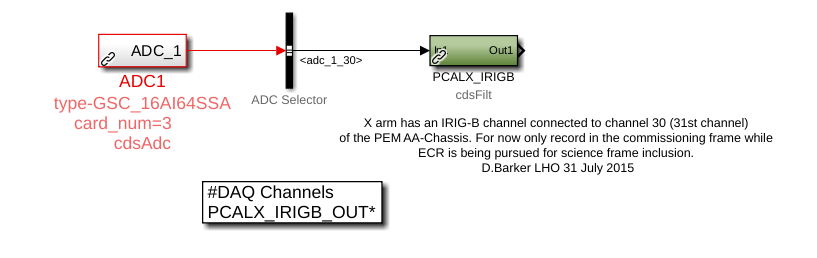
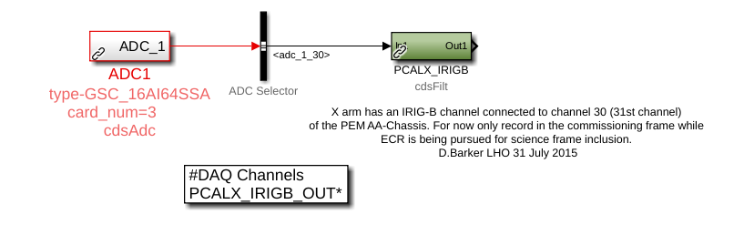
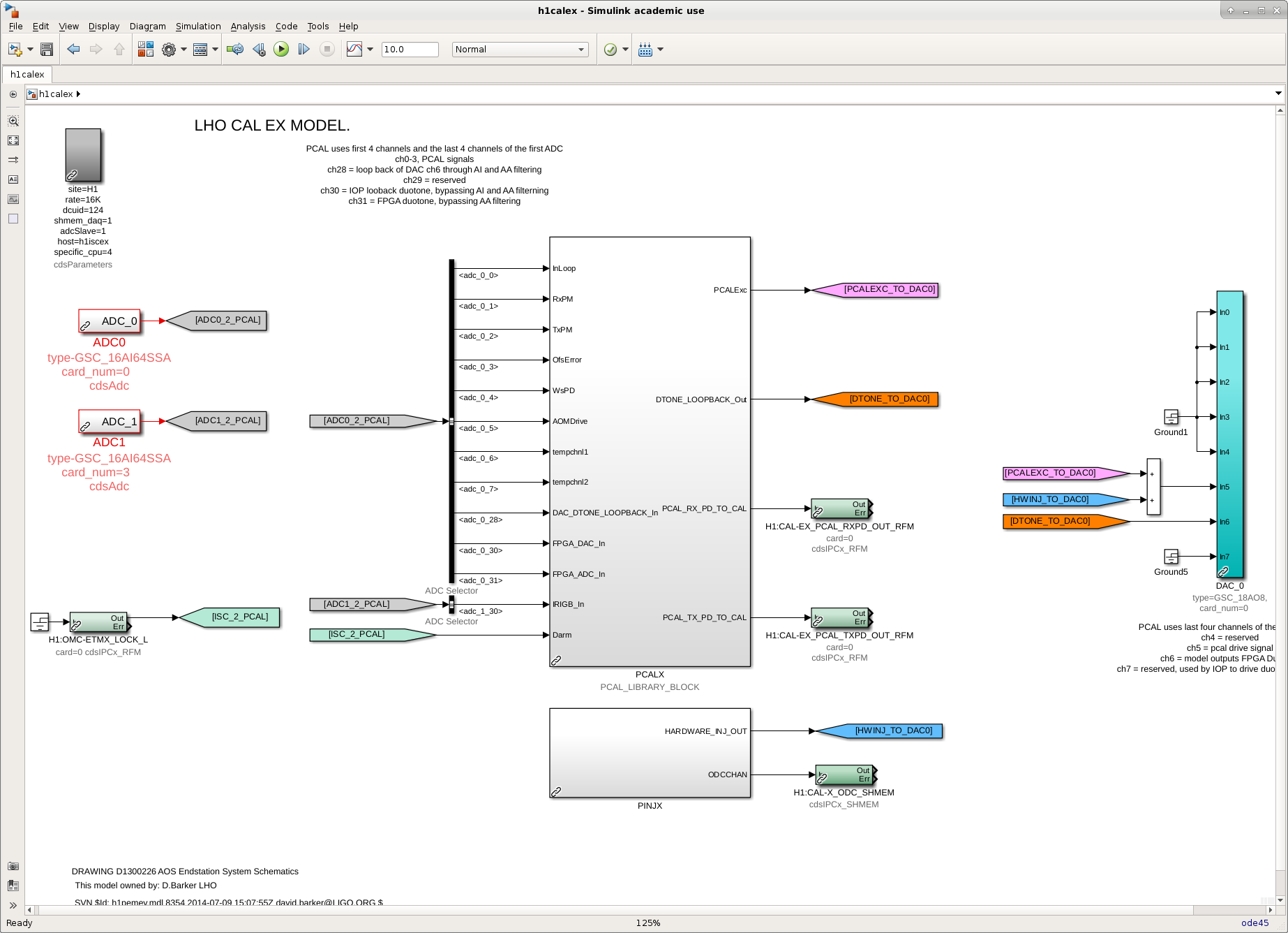
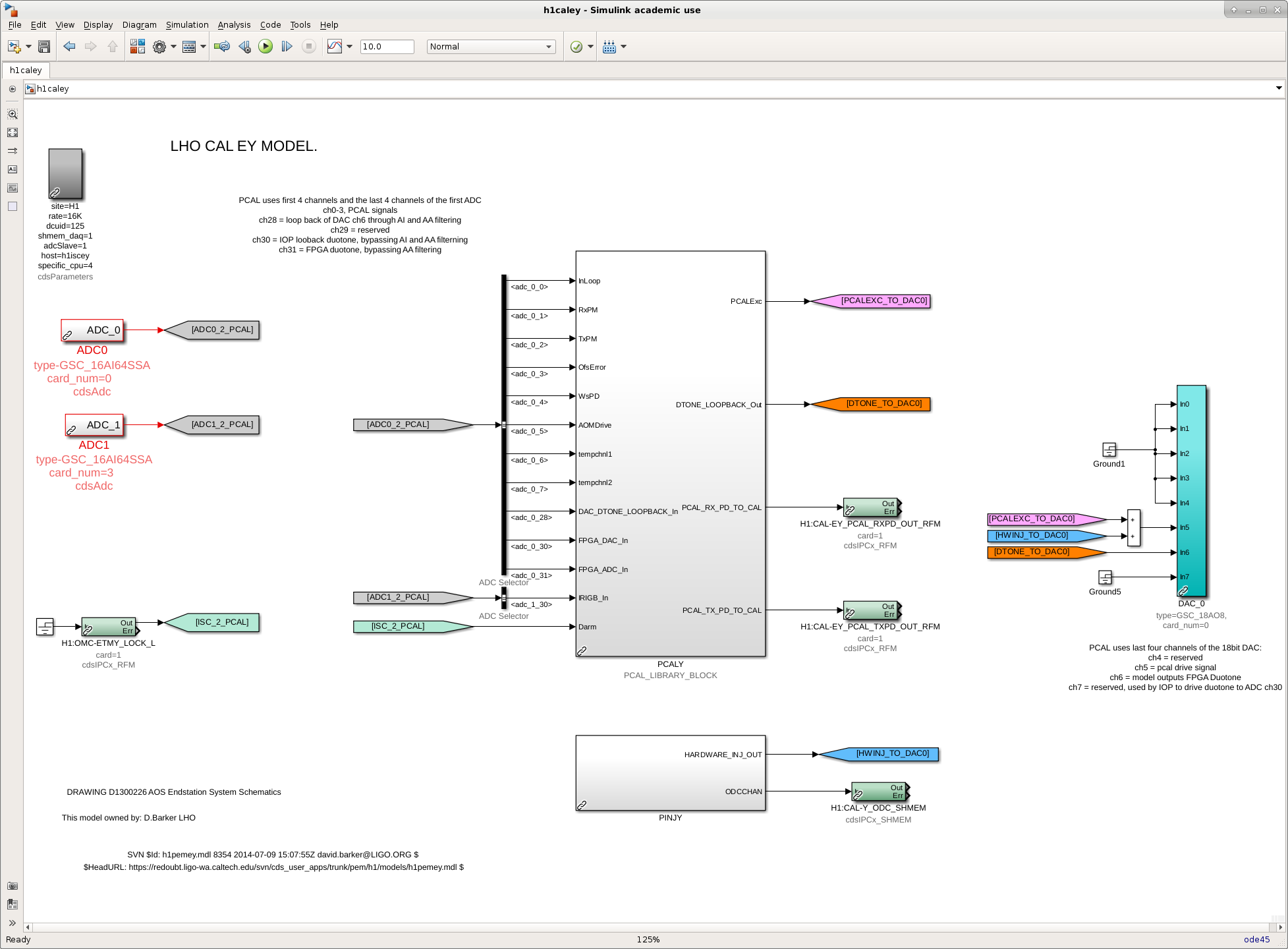
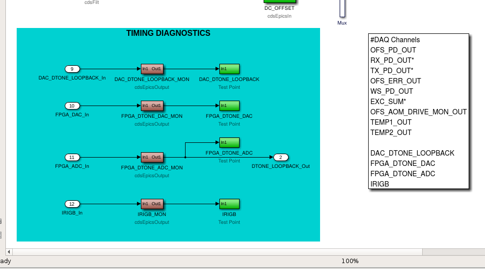
K. Kawabe, J. Kissel Keita informed me of his worries that the PCAL timing monitor system is vulnerable to corruption. Here's why: The fast channels are captured with filter modules, which have excitation points. Some of the channels stored in the frames are the OUTs, which would contain both the monitor signal and any excitation. Further, we don't monitor the excitation point: because the PCALX system is used for continuous wave hardware injections, we must ignore the CDS STATEWORD bit that says "the user model is requesting an excitation" when we check for this before going into OBSERVATION READY. This bit is also what's typically used by the low-latency pipelines know that there's an unwanted injection, but it has been ignored and nothing else was used in its place. Thus, "vulnerable" to corruption by unwanted excitation. As such, I propose the following changes: (1) Replace the capture of these signals with an EPICs readback and fast TestPoint instead of standard filter module. There's no need for filtration or excitation -- this is a monitor only system. (2) Re-organize and rename the channels to be a little more representative of what's going on.** (3) Bring the IRIGB monitor into the PCAL library part. I attach a couple of screenshots that show the before-and-after. The channel name changes would be as follows: $(IFO):CAL-PCAL$(END)_ [...] [...] FPGA_DTONE_IN1_DQ >> [...] FPGA_DTONE_ADC_DQ [...] DAC_NONFILT_DTONE_IN1_DQ >> [...] FPGA_DTONE_DAC_DQ [...] DAC_FILT_DTONE_IN1_DQ >> [...] DAC_DTONE_LOOPBACK_DQ [...] IRIGB_OUT_DQ >> [...] IRIGB_DQ These channels will need to be updated in the GDS broadcaster, and any down-stream low-latency code that uses them (for example, the matlab / python scripts that are used to perform timing diagnostics for candidate GW events). **As a reminder of what all these channels are, and the expected delay in between them, check out Evan Goetz's I/O Chassis Timing Schematic pcal_timing_schematics_LHOaLOG29259.pdf, from G1501170 and LHO aLOG 29259. I've requested some further approval from interested parties, but otherwise the proposal is ready-to-install during tomorrow's maintenance day. If successful, I'll file the ECR for it to be implemented at LLO.
These changes were installed on Jan 08 2019. See LHO aLOG 46291.
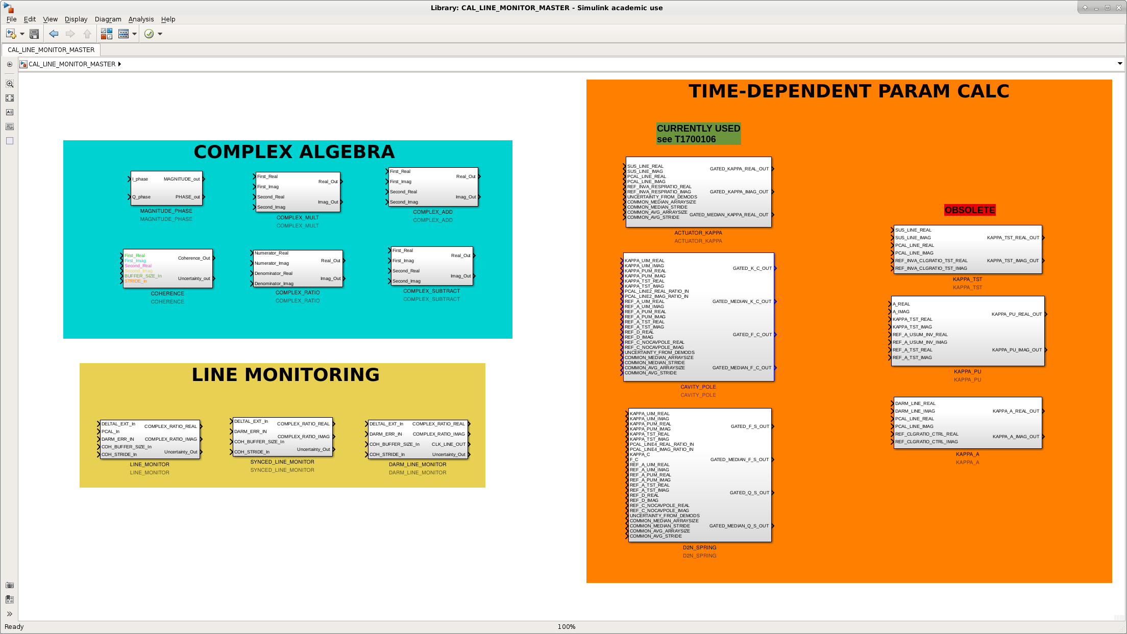
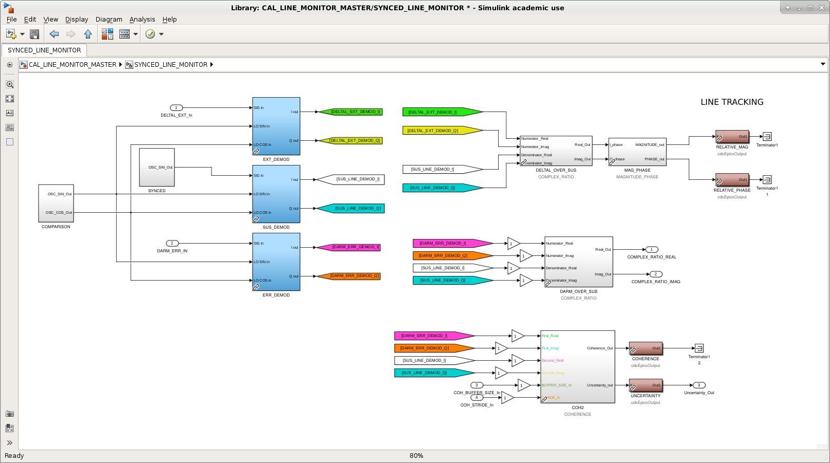
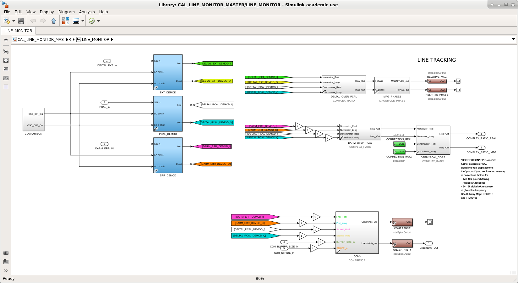
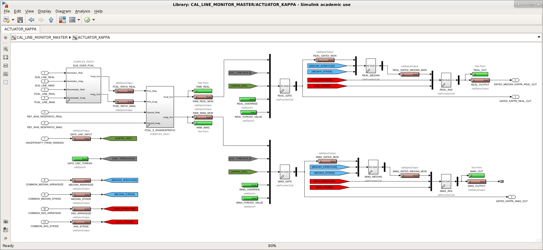
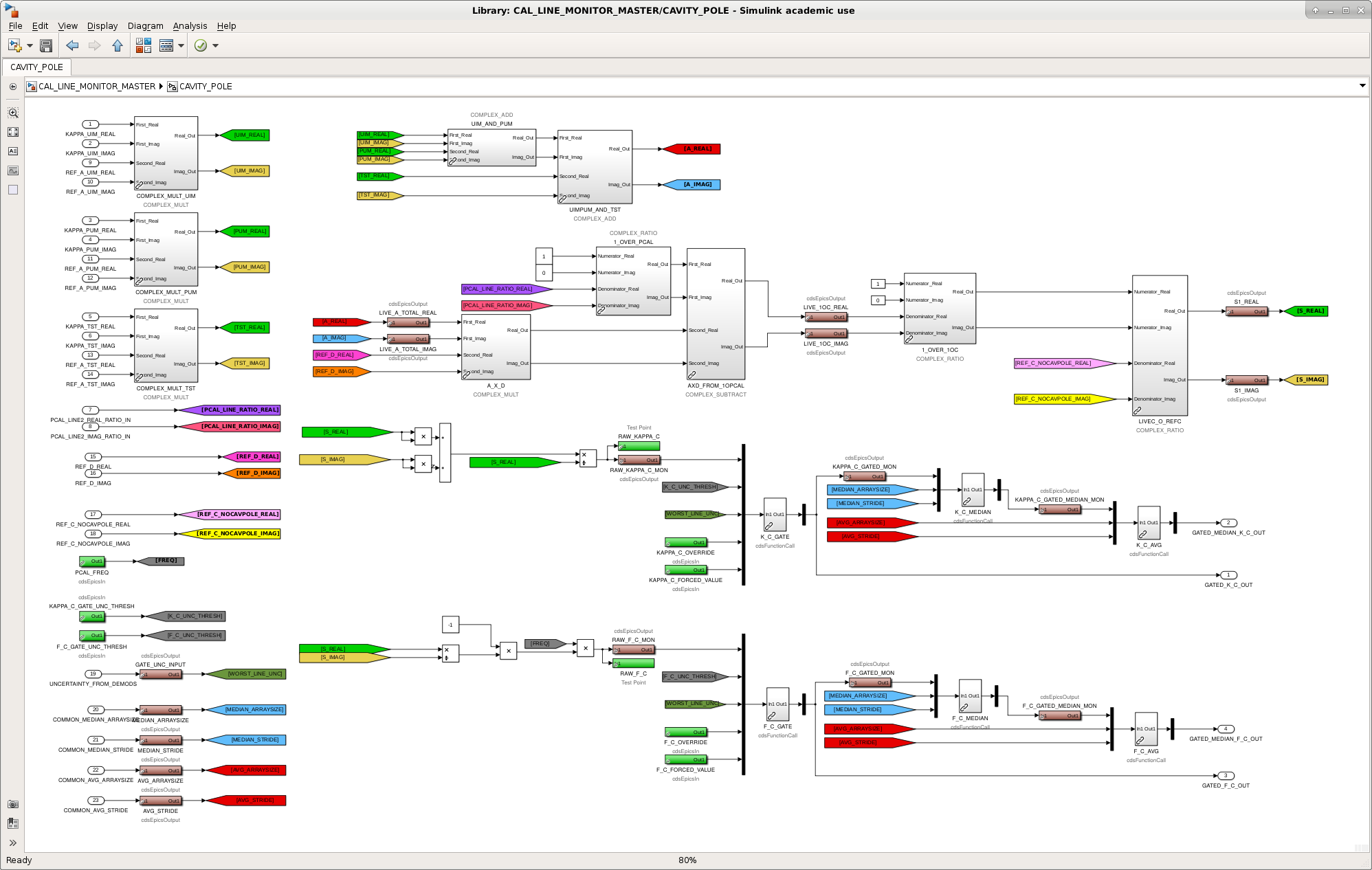
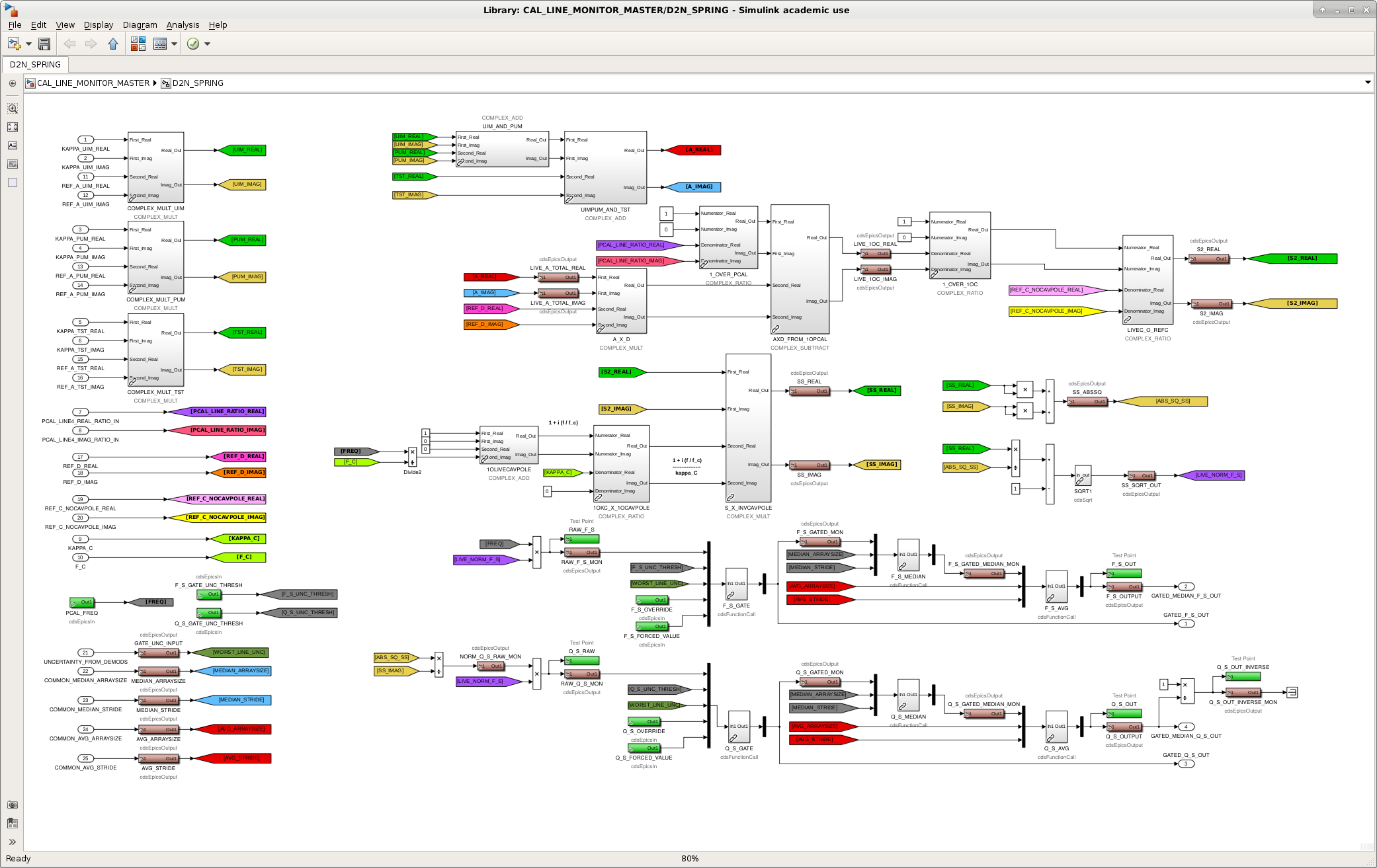
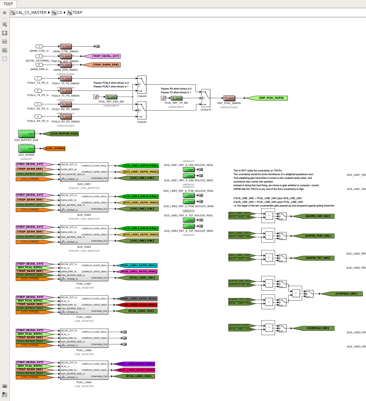
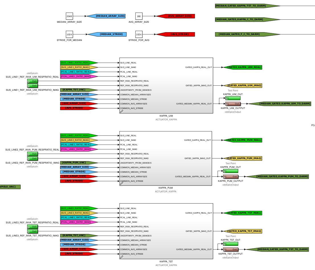
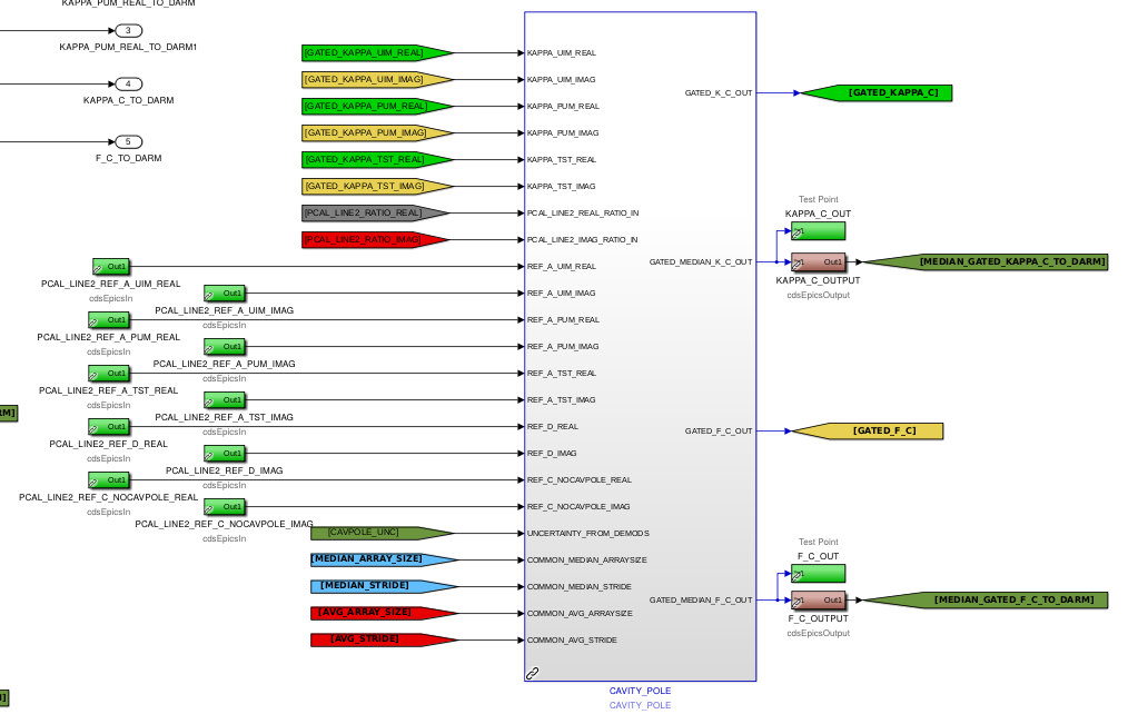
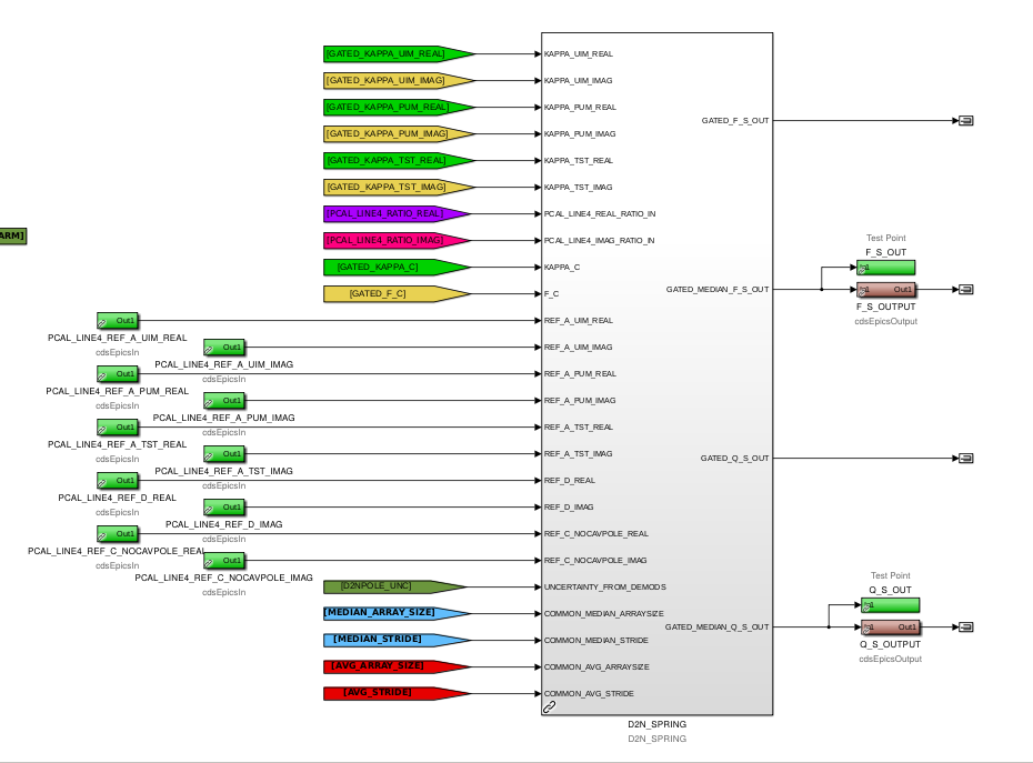
J. Kissel WP #8028 After in-depth investigation, Shivaraj and Saravanan ("S and S") discovered I had made a rather insidious mistake in the calculations for the time-dependent correction factors (TDCFs) for the DARM loop's optical plant. See LHO aLOG 46135 for the full story, but the message is that -- because of poorly labeled basic complex algebra blocks and my lack of careful checking -- I had inserted a multiply when I should have inserted a divide when computing a ratio in the middle of the calculations of kappa_C, f_c, f_s, and Q_s. The bug has been fixed, the model has been compiled, and the plan will be to install it tomorrow when everything is rebooted to upgrade the EEPROMs of all dolphin front-ends (see WP #8030). In detail, I've done the following: (1) I've extracted the D2N_SPRING block from the CS/TDEP level of the IFO generic corner station calibration library part, /opt/rtcds/userapps/release/cal/common/models/CAL_CS_MASTER.mdl and placed it inside the /opt/rtcds/userapps/release/cal/common/models/CAL_LINE_MONITOR_MASTER.mdl to be consistent with what's done with the ACTUATOR_KAPPA and CAVITY_POLE library blocks. Once created as a library part in CAL_LINE_MONITOR_MASTER, I then copied it back into the CS/TDEP subsystem, now as a link to library block in LINE_MONITOR_MASTER. This change is solely for consistency with how things are done for every other TDCF; it does not affect any functionality. (2) In the common library /opt/rtcds/userapps/release/cal/common/models/CAL_LINE_MONITOR_MASTER.mdl I've added a "Description" under the "General" tab of every block's "Properties" pop-up window (opened by right-clicking on the block and selecting "Properties..." from the right-click menu) that is identical to the library block's generic name. Further -- switching over to the "Block Annotation" tab -- I selected the Description property token and put it on the list of text and tokens for annotation. This means that now any time the block is copied from the common library to where it will be used in practice, it will retain an annotation/label showing its basic generic function, even if the block's name is changed. This is especially important for the complex algebra blocks which are used repeatedly all through out a given subsystem level and thus requiring a block name change (hence my mistake that S and S discovered). This change is solely for clarity, and doesn't affect any functionality. (3) I slowly and carefuly re-copied and re-linked all uses of these basic algebra parts into the greater library parts for the ACTUATOR_KAPPA, CAVITY_POLE, D2N_SPRING, LINE_MONITOR (for PCAL_LINE demodulation), and SYNCED_LINE_MONITOR (for SUS_LINE) in the common library /opt/rtcds/userapps/release/cal/common/models/CAL_LINE_MONITOR_MASTER.mdl During this step, I fixed the bug that Shiva and Saravanan identified by replacing the complex multiply with a complex ratio to correctly take the ratio of live C and C_res at the tail end of the computation of S in the CAVITY_POLE and D2N_SPRING library blocks. (4) I re-copied and re-linked all uses of the greater library parts in to the CS/TDEP generic corner station calibration library part, /opt/rtcds/userapps/release/cal/common/models/CAL_CS_MASTER.mdl New screenshots of everything are attached, and all changes the two, above-mentioned, libraries have been committed to the userapps repo.
These changes were installed on Jan 08 2019. See LHO aLOG 46291.
Sheila, Nutsinee
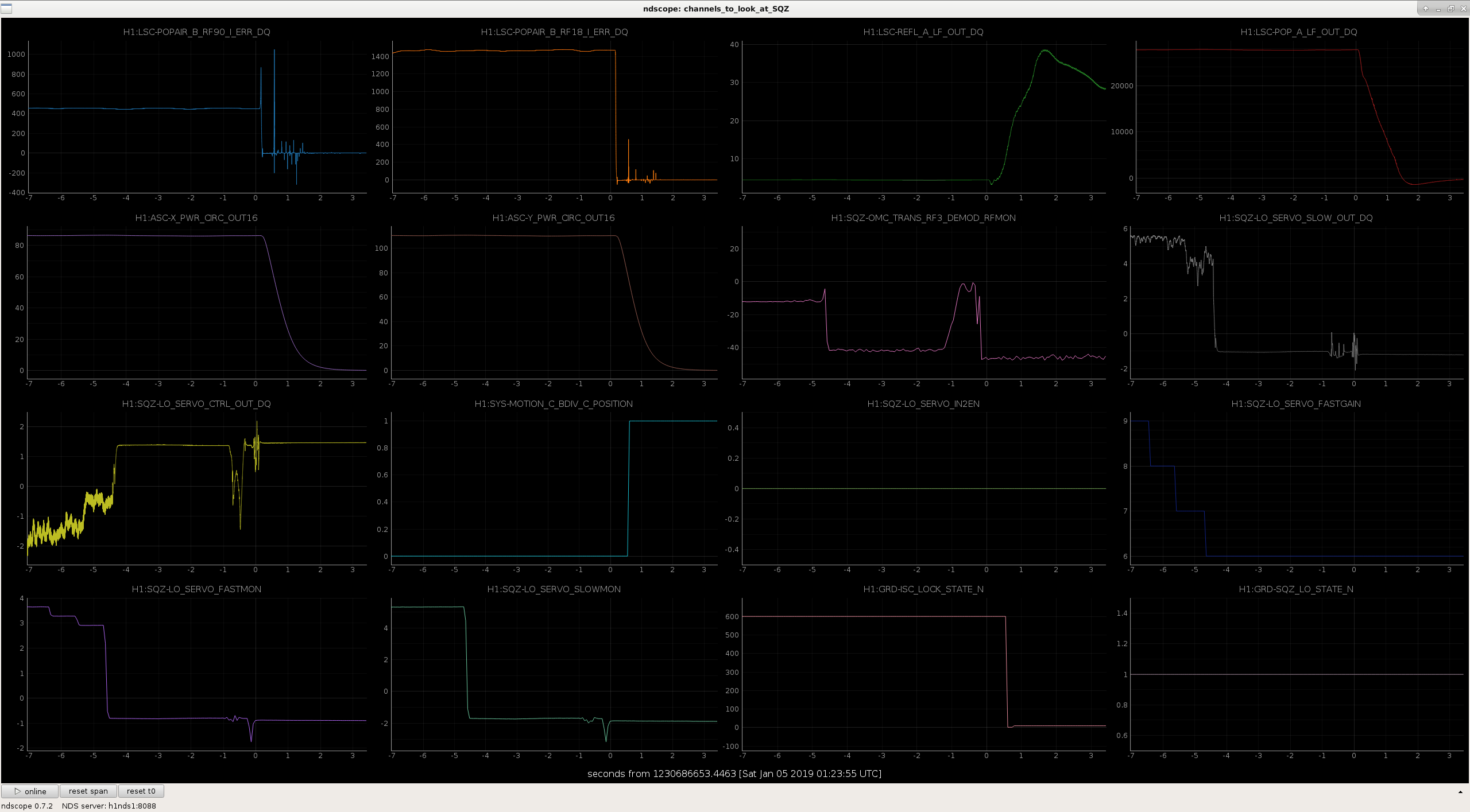
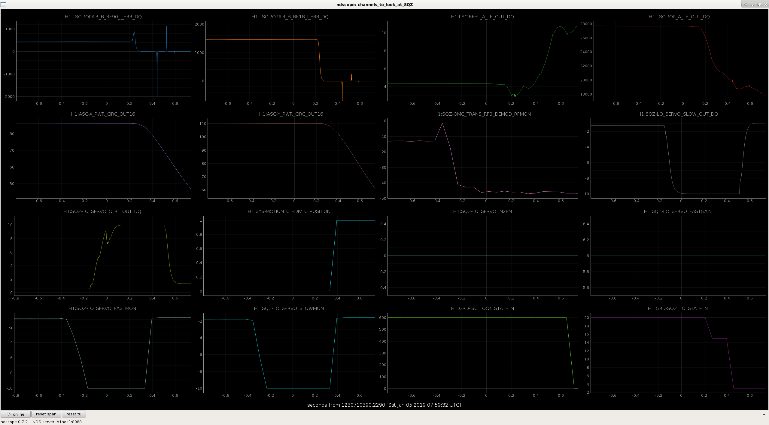
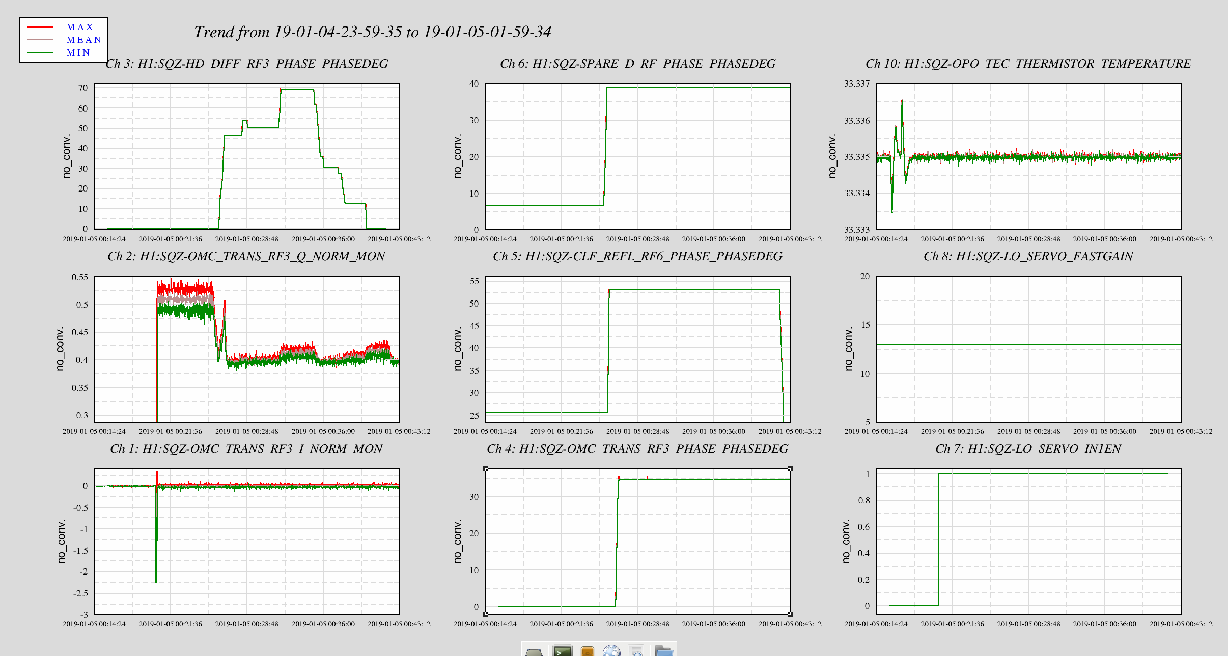
We made a two attempts to inject squeezing today, both times we eventually unlocked the interferometer when the LO servo unlocked. These two locklosses happened at 7:59 UTC and 1:23 UTC today.
We've made some improvements to the automation.
I think looking at LO output and close the shutter when it rails isn't fast enough. We need to look for a pending doom, like a drop in 3MHz signal or error signal. We need a fast channel for this to be able to close beam diverter in time when something goes wrong.
Attached are plots of these two locklosses.
In the first one, the OMC RF3MHz signal drops 4 seconds before the lockloss. We had been checking the LO SERVO fastmon and shutting the beam diverter if it reaches the rails, but this wouldn't have caught either of these LO locklosses. I've changed the SQZ_LO guardian so that it will close the beam diverter if the RF3MHz drops below 20dBm, which would probably have prevented the first of these locklosses. This might not be fast enough to catch locklosses like the second one.
Not relate to this topic. But for the record, Jan 4th was the day we injected squeezing and didn't see anything. We looked into the nlg during the time as we changed 6MHz and 3MHz using Q error signal and turned out we only had nlg of 1.3. This could explain why we didn't see much.
[Keita, Jenne]
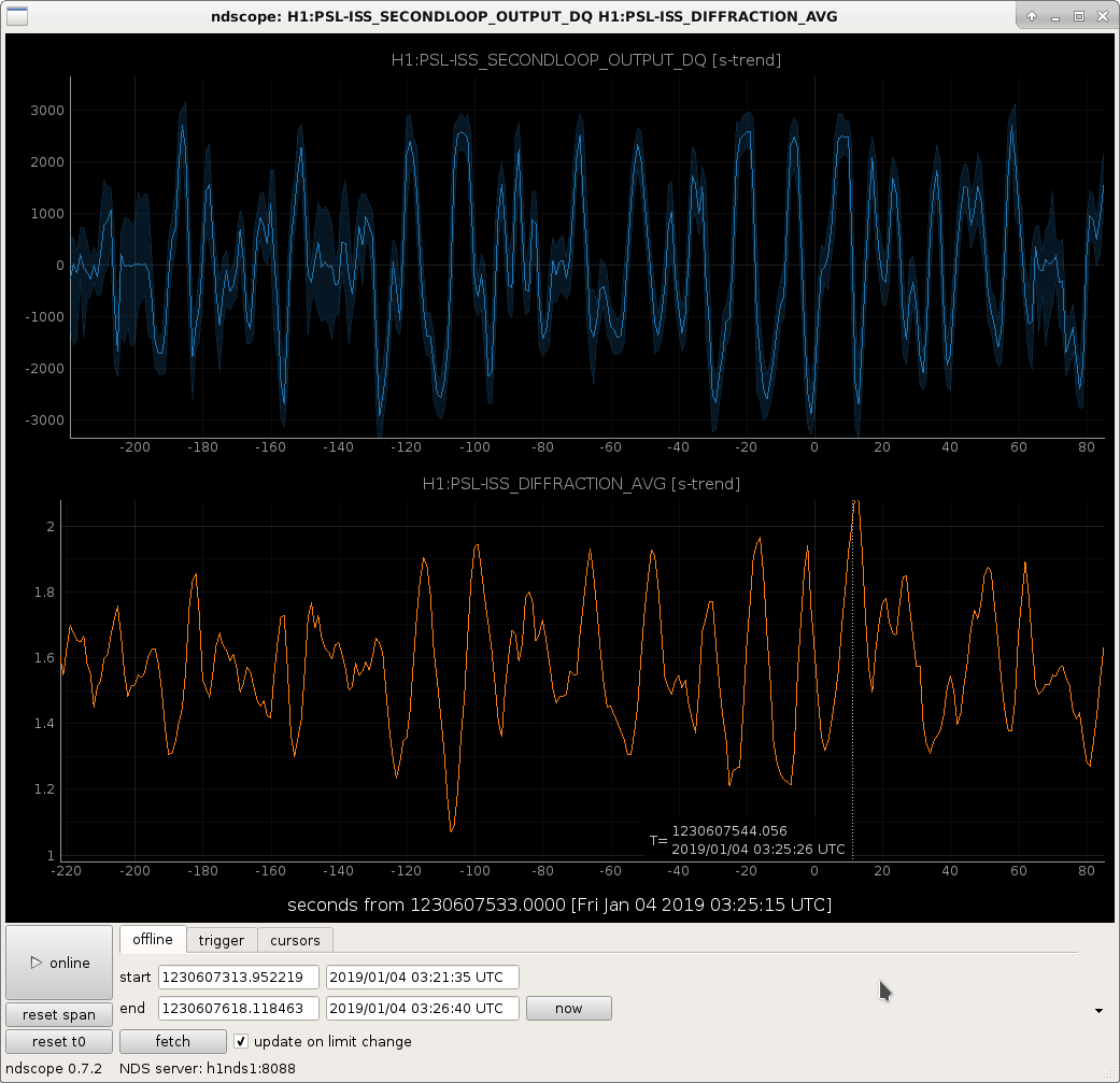
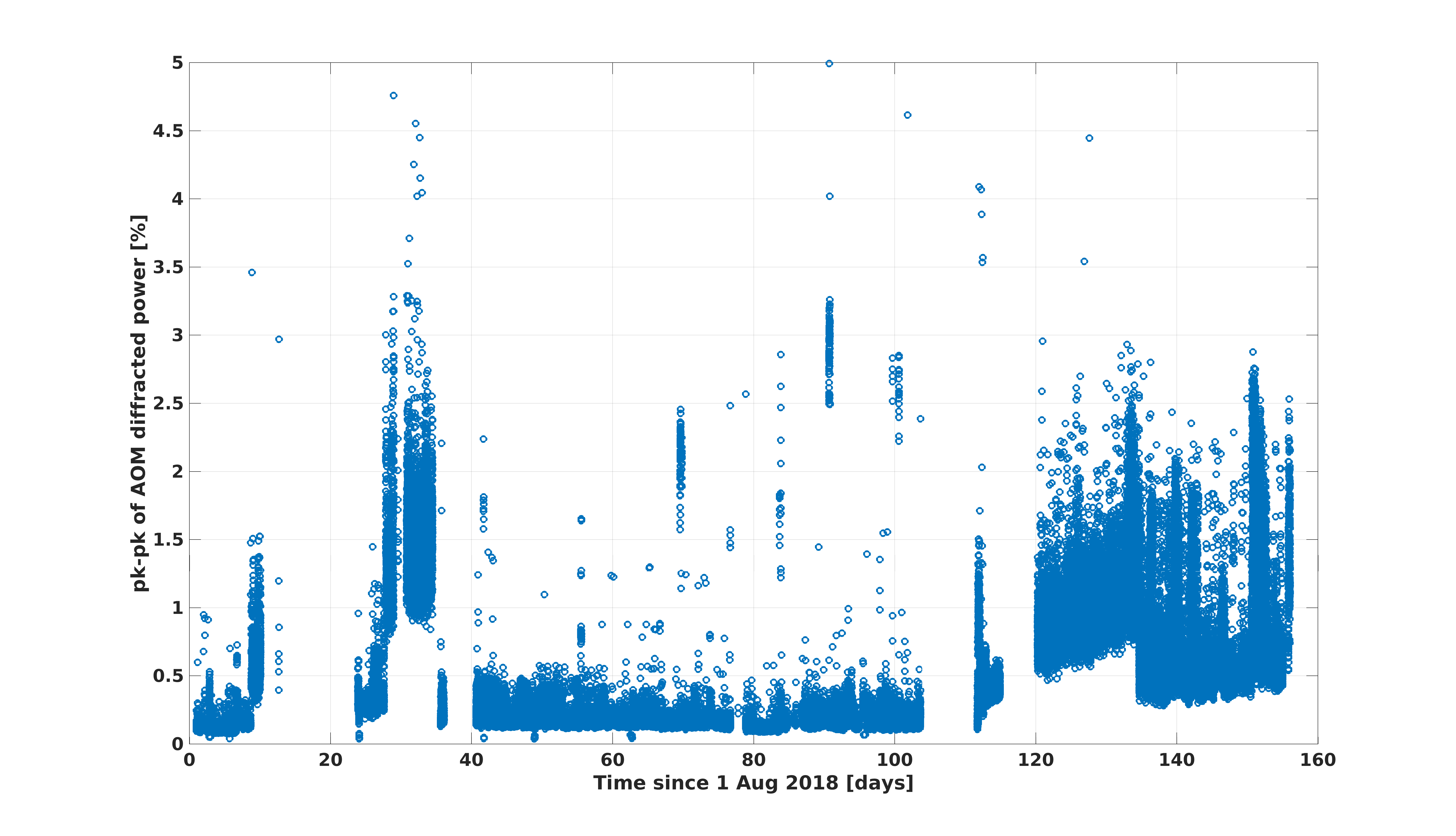
Keita and I have been trying to figure out what is going on with the ISS that is causing the diffracted power to oscillate so largely the past few days. When the IMC is locked, the ISS first loop, with the slow part of the second loop board but not the "second loop" as you would normally think of it, is causing the diffracted power to oscillate more than 1.5%. This is very large compared to what it ought to be.
In the attached plot, I have the peak-to-peak values of the diffracted power, from August 1st 2018 through yesterday. I'm using the max and min of minute trends, so this won't catch if some short period of time has a small pk-pk value, but will see larger trends. Data is only plotted here if the first loop is closed, the second loop is open, but the second loop is sending signal from the slow loop over to the first loop (yes, the ISS is confusing...). That is, this should represent times when the IMC is locked, or we're trying to acquire IFO lock, but not times when the second loop is actually feeding back using IMC transmitted power (this is engaged in guardian once DRMI is locked).
You can see that there was a time in ~September that the diffracted power oscillations were high, but then they got better. Since the beginning of December, the peak-to-peak value hasn't been near it's normal small value.
It seems like the second loop board is picking up more noise somehow, somewhere, and is feeding that through the slow portion of the board to the AOM. When we turn off the output of the second loop board, we immediately see that the diffracted power becomes nice and smooth and quiet (we tried this briefly yesterday). Still under investigation, but something is definitely not right.
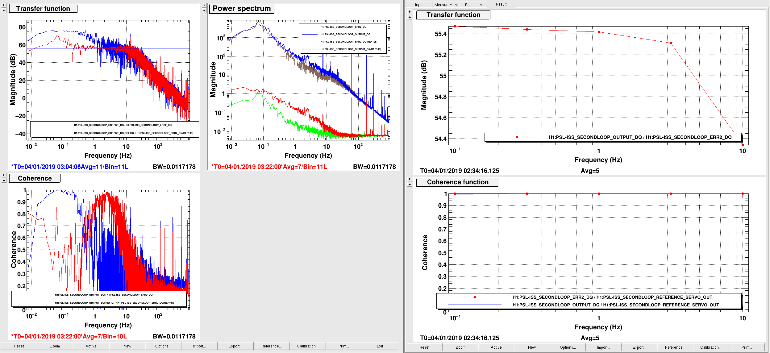
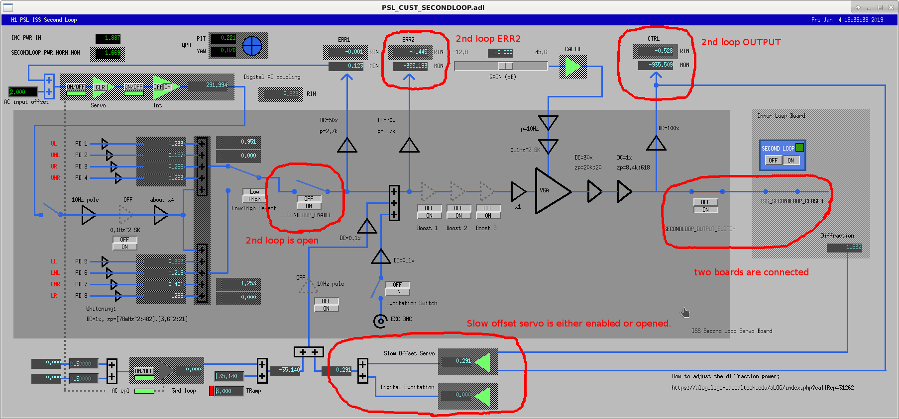
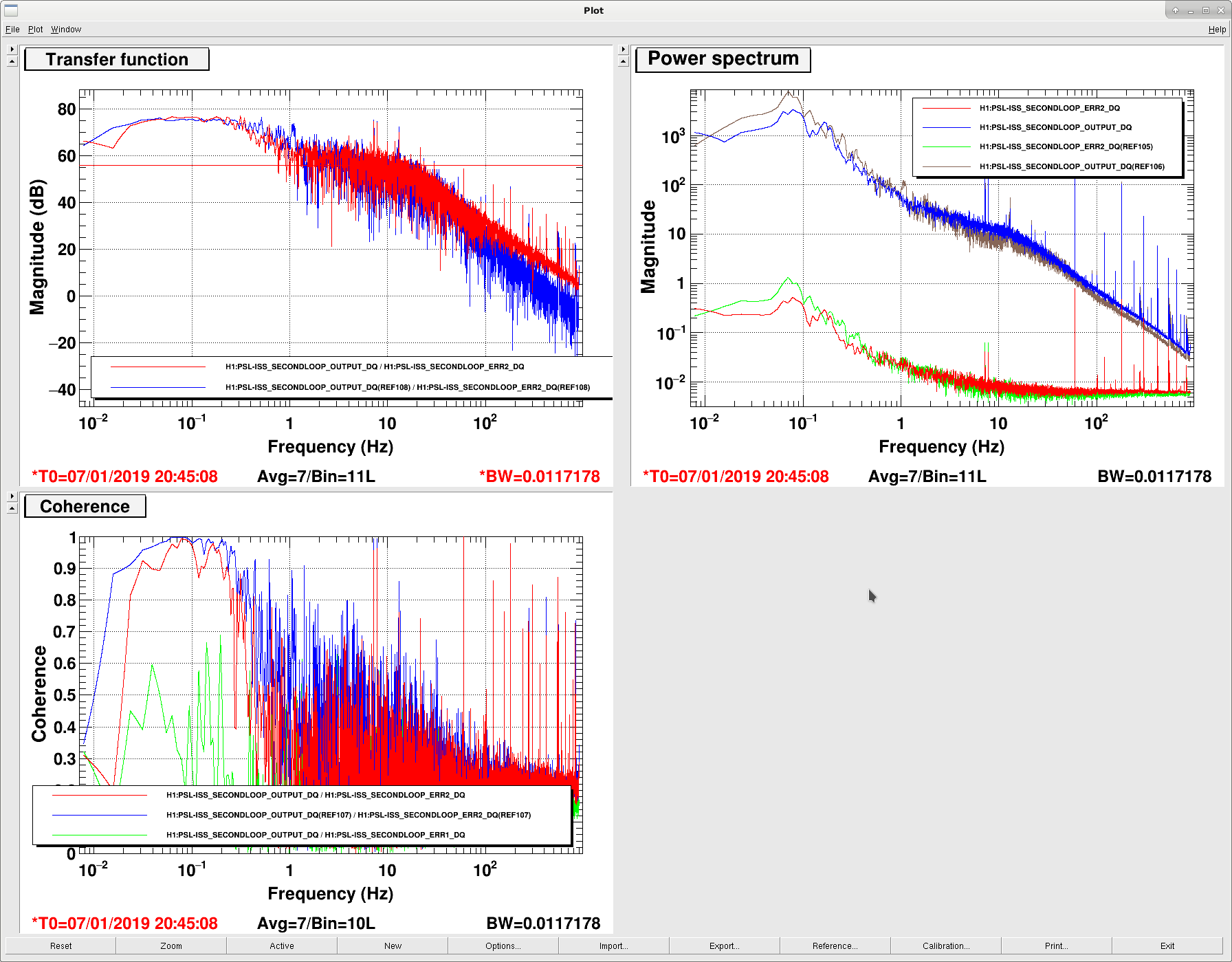
First attachment shows that the 2nd board output is pushing the 1st loop board when both the output switch in the 2nd loop board and the 2nd loop enable switch in the 1st loop board are on, even when the 2nd loop itself is open and even when slow offset servo is off, i.e. even when the 2nd loop output is entirely driven by the noise of the board itself. (The plot was taken when the slow offset feedback was on but the 2nd loop was off, but slow offset on/off doesn't make much difference if at all.)
Second attachment shows that the board is either generating or picking up some noise at around 0.1Hz downstream of ERR2, driving the board output. Let me explain.
On the left is the non-driven noise transfer function from ERR2 to OUTPUT. ERR2 is the error point readback downstream of the summation point for the slow offset feedback. Live and ref traces show the slow offset feedback on (live) and off (ref). See the third attachment to see the board configuration and to understand which channel is what.
Without slow offset feedback(left of the left plot, blue), the coherence at 0.1Hz is almost 1, but the transfer function, which is supposed to be 56dB for f<20Hz, is about 20dB larger than it should be.
With slow offset feedback (red), the coherence at 0.1Hz goes down but instead the coherence becomes high at a few Hz, and where the coherence is high the transfer function is 56dB (red). That's because the board output didn't change for f<0.5Hz or so with or without slow feedback (right top panel of the left plot), but ERR2 increased for f<10Hz when slow offset feedback was on, and this was also visible in the board output in [1, 10] Hz.
When you make a driven TF even when slow feedback is on (right of the left plot) it was right at 56dB, though.
All these mean is that ERR2 (when slow feedback is off) and OUTPUT see the same noise peaking at 0.1Hz (because coherence is 1) and that the noise cannot be present in the board upstream of ERR2 i.e. summation point output (because TF is not 56dB). The noise in OUTPUT is a real problem and it seems to have become worse recently, judging from people's complaint.
Noise in ERR2 is probably not a real problem as that is not causing the OUTPUT to swing, at least not as of now. ERR2 monitor is merely picking the same noise somehow, quite possibly it's picking up the OUTPUT directly.
I don't have any explanation for the noise shape peaking at 0.1Hz.
[Daniel, Keita, Jenne]
Marc and Richard are looking into whether we have a spare ISS Second Loop chassis (it sounds like we do), to swap in. The output of the current board is drifting a lot, about 30mV pk-pk (it's roughly 10,000 counts that we are seeing on the monitor, which translates to about 30mV at the actual board output once you take the 100x gain of the monitor into account).
This noise is being introduced between the 1st and 2nd boosts. Engaging either boost 2 or boost 3 seems to amplify the noise, and the output (H1:PSL-ISS_SECONDLOOP_OUTPUT_MON) moves by a huge amount. However engaging only boost 1 does not amplify the noise. With only boost 1 engaged, the offset is increased as expected, but the pk-pk output drift is back to about 10,000 counts. We had also changed the output gain (H1:PSL-ISS_SECONDLOOP_GAIN) and saw that the noise is amplified by that gain. Since this gain is after the 3 boosts, we started working toward the input of the board, and tried engaging the boosts one at a time, as described above.
Keita had a look at the schematic (D1600298), and the current suspicion is that the switch for boost 1 is busted. Perhaps when we're requesting that boost 1 be off (bypassing the opamp stage), the switch is still a little bit connected to the output of the opamp stage, so we're getting weird feedback loops that shouldn't exist. This weird feedback loop could be how the error point monitor (H1:PSL-ISS_SECONDLOOP_ERR2_MON) is coherent with this noise, since that monitor is at the input to boost 1.
If we have a chance today (otherwise it'll happen tomorrow) we'll swap in the spare ISS second loop chassis, and can confirm the problem with the currently-installed chassis, and replace that switch.
Other observations are that if we significantly increase the gain of the slow reference servo, we can suppress the noise that is being introduced between the boost stages. However, that would mean that the reference servo is marginally stable, so we don't actually want to run like that. (And, anyway, we want to fix the problem, not just work around it). Also, Sheila and Keita were able to DC couple the ISS second loop on Thursday (alog 46229), and when the loop was DC coupled the noise was again suppressed.
For our current lock, we have the Second Loop board entirely disconnected from the First Loop board (switches H1:PSL-ISS_SECONDLOOP_OUTPUT_SWITCH_MON and H1:PSL-ISS_SECONDLOOP_CLOSED are both open).
So much for the broken switch theory.
I and Fil changed the chassis (old one: S1700062, new one: S1700063) but it seems like the noise didn't change much if any. In the attached, current traces are now and references are with the old board.
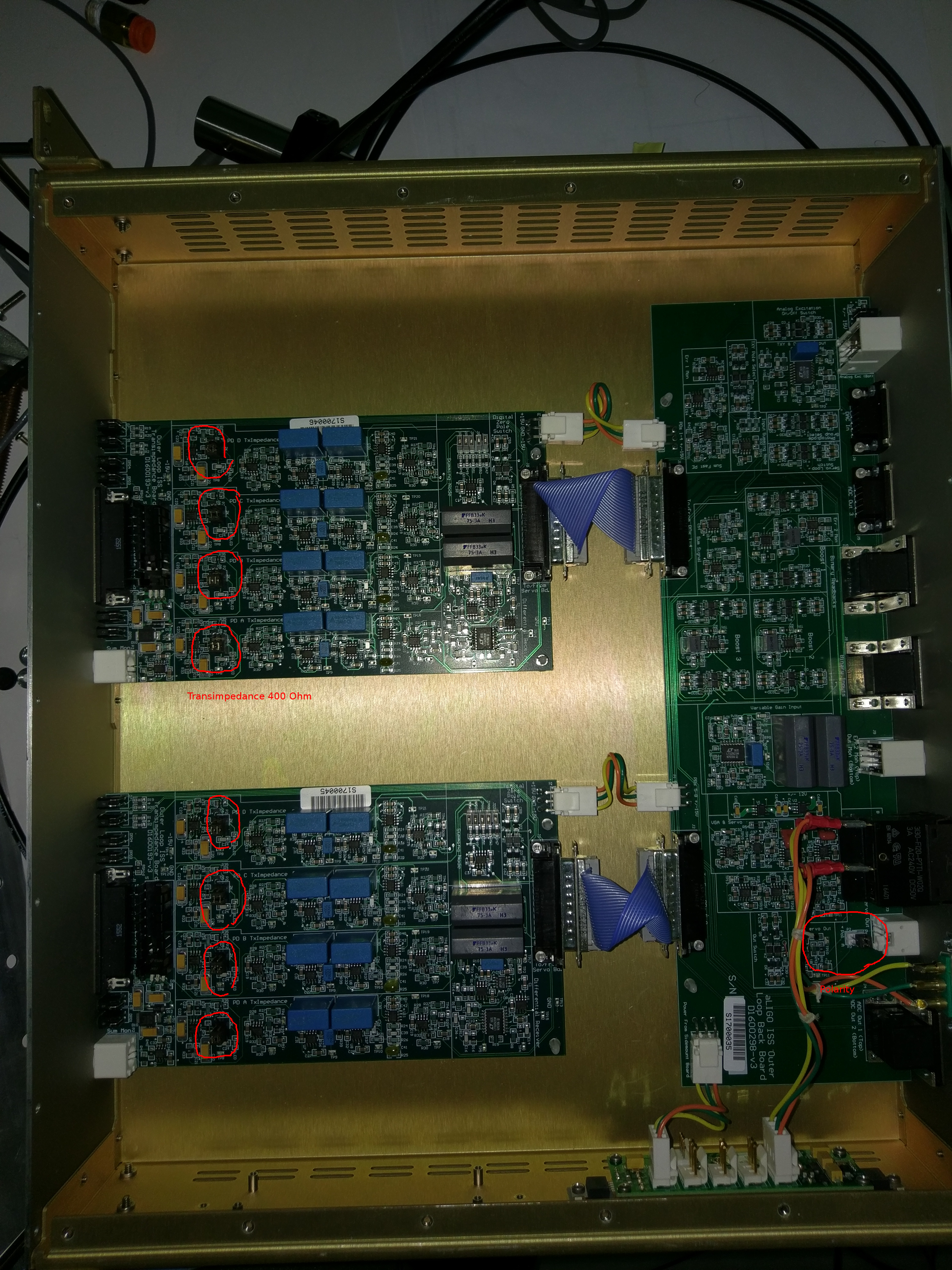
BTW, just for documentation purpose, attached is the photo of the boards with jumpers for correct transimpedance (400 Ohm) and output polarity.
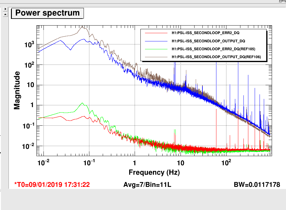
Note that the noise goes up and down on its own. Today at random time I measured the board output and the peak at 0.1Hz was much smaller than it used to be though it's not gone either (1st attachment).
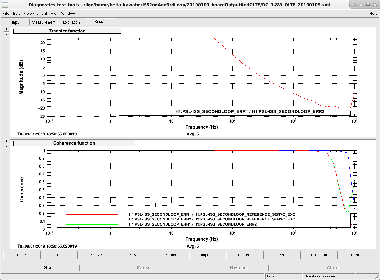
Also as a side note, ISS 2nd loop gain is too small, though this is not related to the problem discussed in this thread (2nd attachment).
At 2W, DC coupled, no boost, with 20dB slider, UGF is about 280Hz, and the UGF will only increase to about 4.7kHz or so at 30W, but we should push it to 10 or 20kHz (that's what we did in O2).
Since increasing the slider before DC coupling will only worsen the problem discussed in this thread, we need to think about increasing the slider after DC coupling the loop.
Marc Daniel
The output offset shifts seen in the installed units cannot be reproduced in the shop. There, the unit seems to be at least 10 less "shifty."
We discovered an unused OpAmp in a 4 device package that wasn't connected to anything (U2B on D1600298). Not a good idea, since it could be oscillating and effect the devices in the same package.
Things to consider in D1600298: