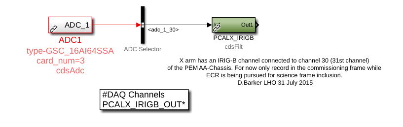
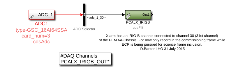
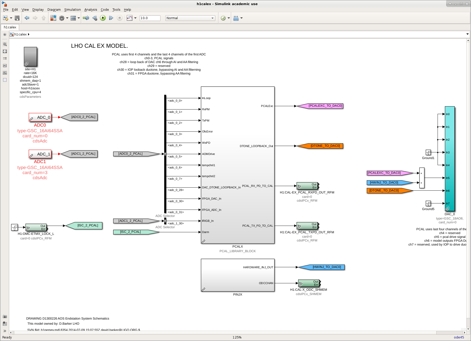
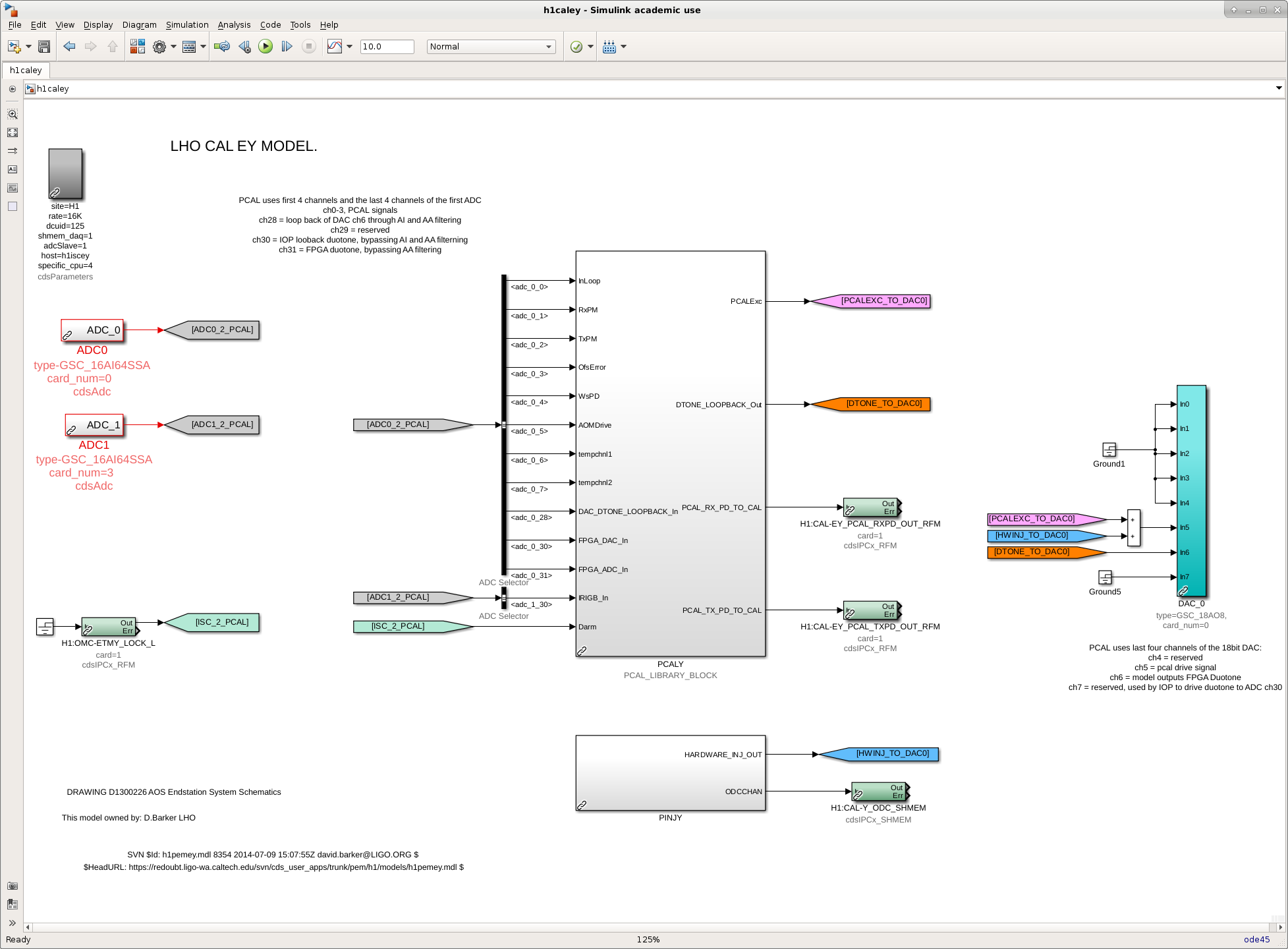
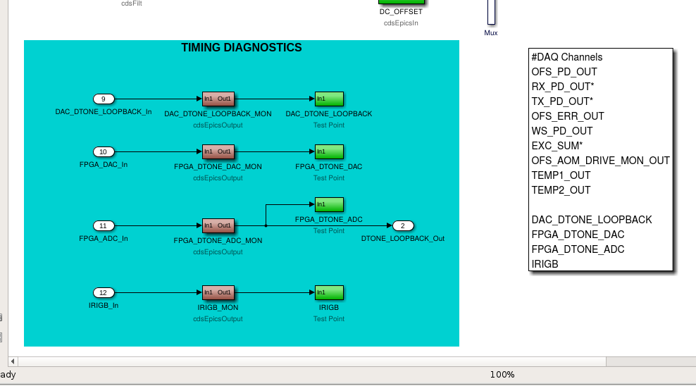
K. Kawabe, J. Kissel Keita informed me of his worries that the PCAL timing monitor system is vulnerable to corruption. Here's why: The fast channels are captured with filter modules, which have excitation points. Some of the channels stored in the frames are the OUTs, which would contain both the monitor signal and any excitation. Further, we don't monitor the excitation point: because the PCALX system is used for continuous wave hardware injections, we must ignore the CDS STATEWORD bit that says "the user model is requesting an excitation" when we check for this before going into OBSERVATION READY. This bit is also what's typically used by the low-latency pipelines know that there's an unwanted injection, but it has been ignored and nothing else was used in its place. Thus, "vulnerable" to corruption by unwanted excitation. As such, I propose the following changes: (1) Replace the capture of these signals with an EPICs readback and fast TestPoint instead of standard filter module. There's no need for filtration or excitation -- this is a monitor only system. (2) Re-organize and rename the channels to be a little more representative of what's going on.** (3) Bring the IRIGB monitor into the PCAL library part. I attach a couple of screenshots that show the before-and-after. The channel name changes would be as follows: $(IFO):CAL-PCAL$(END)_ [...] [...] FPGA_DTONE_IN1_DQ >> [...] FPGA_DTONE_ADC_DQ [...] DAC_NONFILT_DTONE_IN1_DQ >> [...] FPGA_DTONE_DAC_DQ [...] DAC_FILT_DTONE_IN1_DQ >> [...] DAC_DTONE_LOOPBACK_DQ [...] IRIGB_OUT_DQ >> [...] IRIGB_DQ These channels will need to be updated in the GDS broadcaster, and any down-stream low-latency code that uses them (for example, the matlab / python scripts that are used to perform timing diagnostics for candidate GW events). **As a reminder of what all these channels are, and the expected delay in between them, check out Evan Goetz's I/O Chassis Timing Schematic pcal_timing_schematics_LHOaLOG29259.pdf, from G1501170 and LHO aLOG 29259. I've requested some further approval from interested parties, but otherwise the proposal is ready-to-install during tomorrow's maintenance day. If successful, I'll file the ECR for it to be implemented at LLO.
These changes were installed on Jan 08 2019. See LHO aLOG 46291.
(Patrick, Filiberto, Richard, Gerardo)
Patrick found that the gauge at IP18 (X2-8) had flat lined about a month ago (12/10/2018), yes there was an alarm that was triggered, but somehow it went ignored, a reason why the alarms were ignored is that the populated field on the MEDM screen showed the last number, which appeared to be a "good pressure" thus showing a green number, but it was not updating.
So we ran a couple of test on a spare gauge, we found out that if the power to the gauge is decreased slow the gauge will shut off at 18.0 volts, for the gauge tested the last number remained on display, on this case at 1 atm. Then if the power is restored slow or fast (voltage is ramped up or switched on at a selected voltage) the EtherCAT part of the gauge does not comeback, unless the voltage is above 22.0 volts. Remember that these units (X2-8 and Y2-8) are powered by batteries charged by the solar panels.
We are still looking into the behavior of the gauges when they lose power, since Y2-8 goes to zero and X2-8 last number remains.
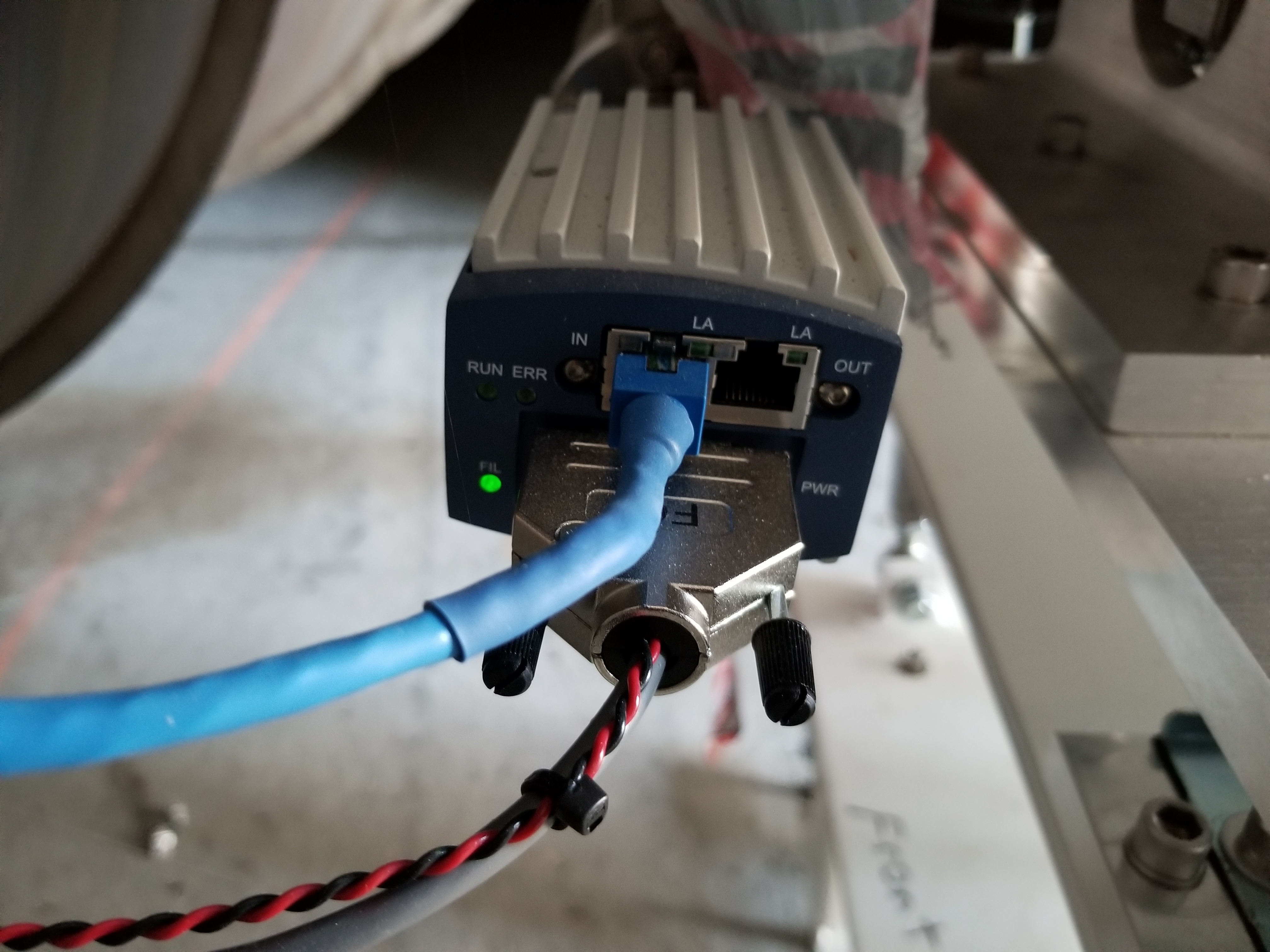
To add to the confusion I'm attaching a photo of the gauge as found, note the FIL light is on and steady green, when Y2-8 failed the FIL light was on but steady red.
The newly rebuilt 2500 l/s ion pump (at X-mid) is ready for installation tomorrow. Gerardo and I had already tested it on the VEA floor last month. I vented it with UHP N2 this afternoon and removed the fasteners from its 16.5" blank flange. I climbed around on the recently erected scaffolding (thanks Chris S., Bubba G.) -seams sturdy and is tagged Ready for Use. I also positioned pump carts and gas bottles etc...
After energizing the MTP controller to charge the levitation batteries and noticed that the long-idle Turbo (stopped) was 2 Torr and the foreline was 780 Torr. There is a known leak in the foreline. As the manual isolation valve at the Turbo Header is closed, this should have remained at rough vacuum. I removed all of the KF fittings that I could and blanked-off just past the leak detector connection and pumped out this new minimal volume with the scroll pump -> Though the scroll pump can bring this minimal-fitting foreline down to 3.5 x 10⁻² Torr, the foreline pressure rises rapidly once the scroll pump is isolated. I'll investigate more tomorrow. For tonight, we won't run the Turbo.
I rebooted h1build at 15:19PST to clear its /var/log disk space. This machine is in heavy use today preparing for tomorrow's maintenance so I needed to fix this issue immediately.
TITLE: 01/07 Day Shift: 16:00-00:00 UTC (08:00-16:00 PST), all times posted in UTC
STATE of H1: Commissioning
INCOMING OPERATOR: Patrick is covering the last hour or so
SHIFT SUMMARY:
LOG:
23:44 UTC Jeff J. and Rahul back from mid X
We now have nearly .4 mW of PSL LO on SQZT6 (used to be just ~100uW). This is plenty of dark noise clearance for SQZ measurement on the homodyne using PSL LO. I didn't measure what comes out of PSL LO fiber recently (measured 1mW on Dec 12). Judging from PSL ref cav transmission power it could be 30% less.
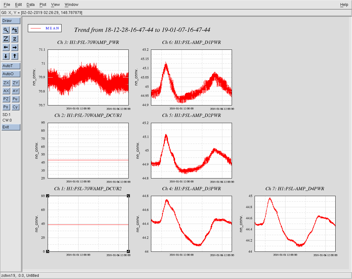
J. Kissel reporting for J. Driggers, S. Dwyer, K. Kawabe, J. Oberling [remotely], D. Sigg, and C. Vorvick Around the time that Keita was replacing the ISS 2nd loop chassis (work permit to be filed, aLOG pending ...), the external shutter for the PSL 70 W amplifier tripped. We (at Jason's instruction) were able to reset the shutter by opening the FLOW RESET screen under the EXTERNAL SHUTTER REQUEST box of the LASER MONITOR screen, and confirming that we want to open the shutter. The suspicion, informed by previous work on the DBB in the same PSL racks, is that Keita's work in the PSL racks glitched the flow sensor(s), which tripped the PSL's external shutter. IFO is back on its way up the lock-acquisition ladder, with no harm done -- just a bit of lost time. The lost time was than "usual" because - it was exactly over lunch when folks were in-and-out of the control room and thus creating "who's actually fixing it?" confusion, and - both Jason and Peter are coincidentally out; let's call it a "learning experience" instead of FAULT. The true, underlying FAULT, is that any work in the PSL racks glitch the PSL water flow sensors enough to trip the shutter.
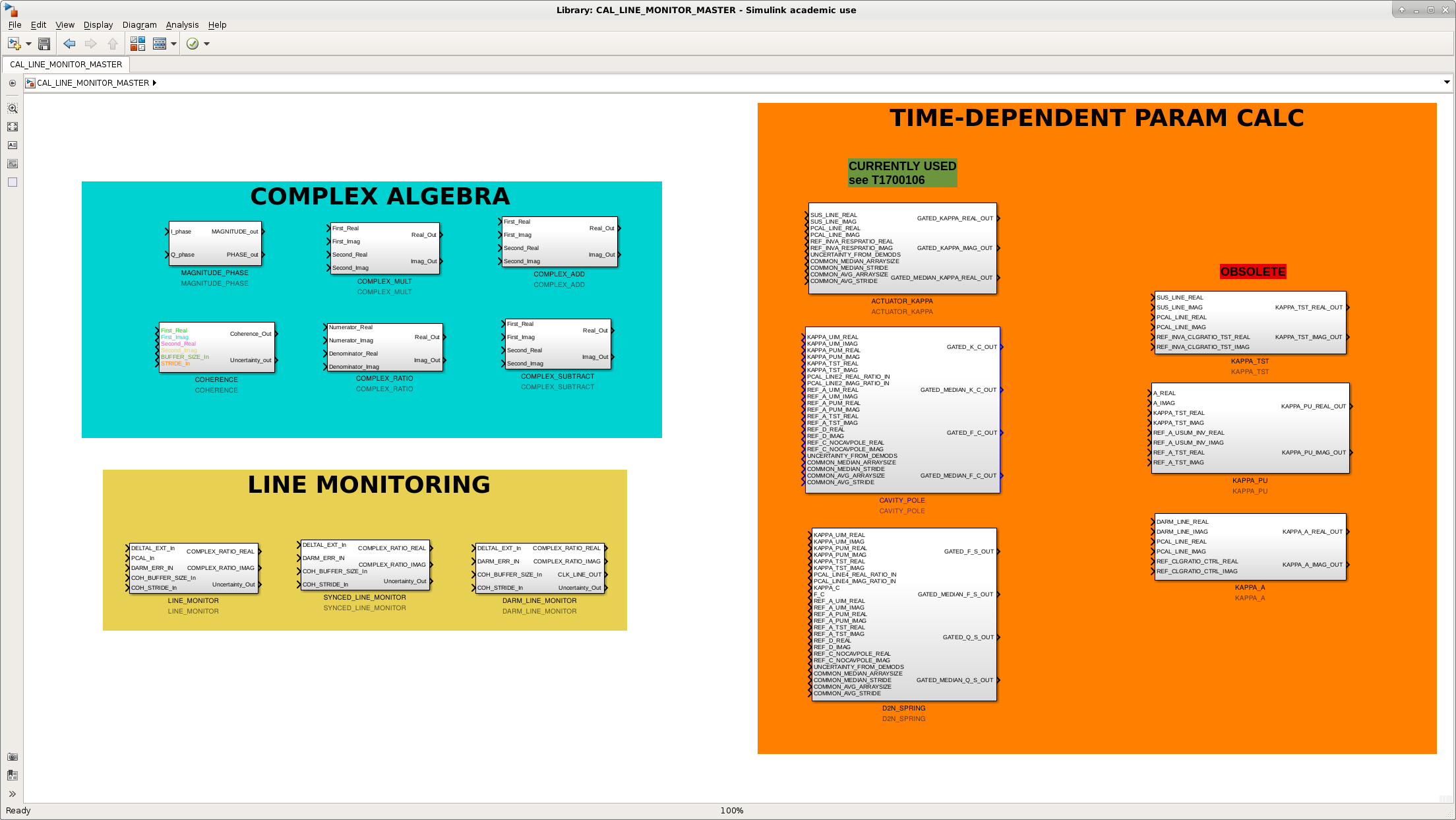
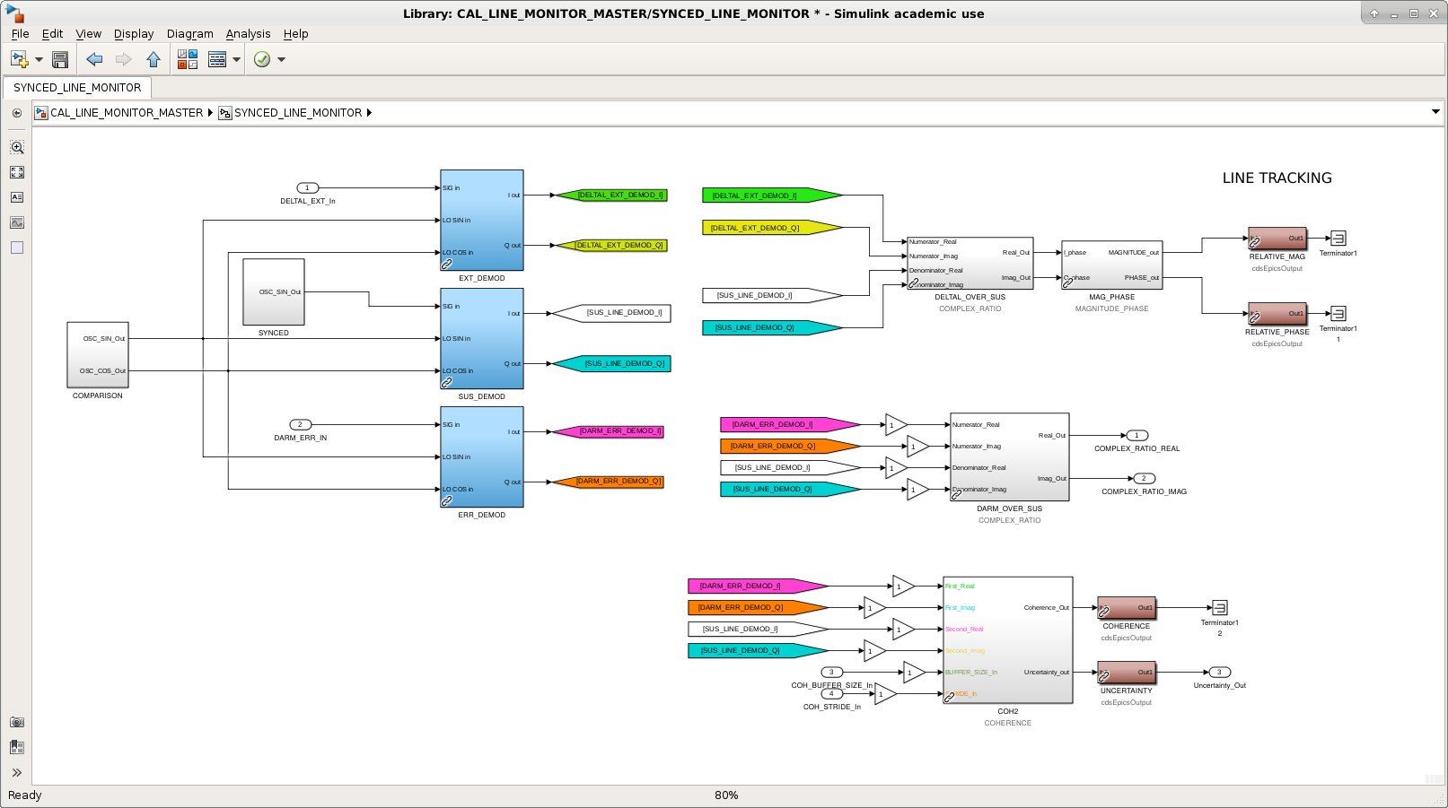
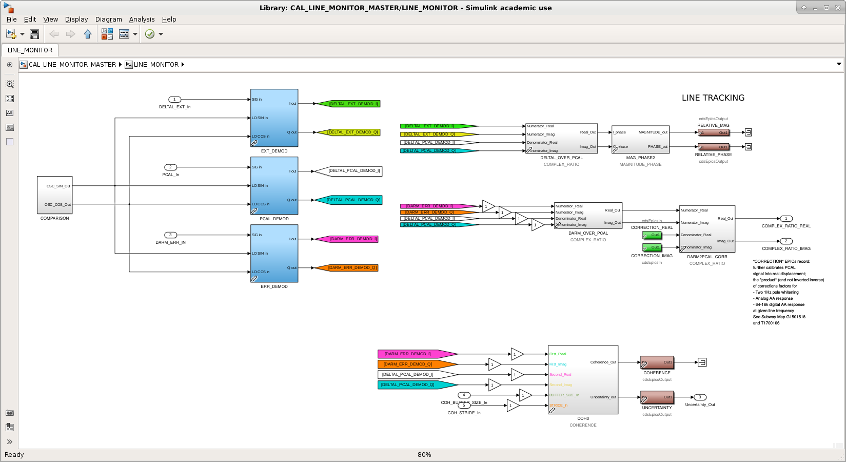
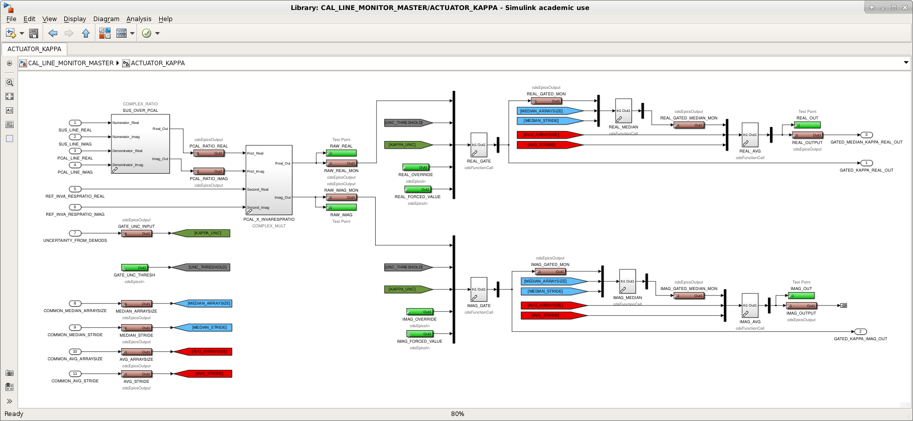
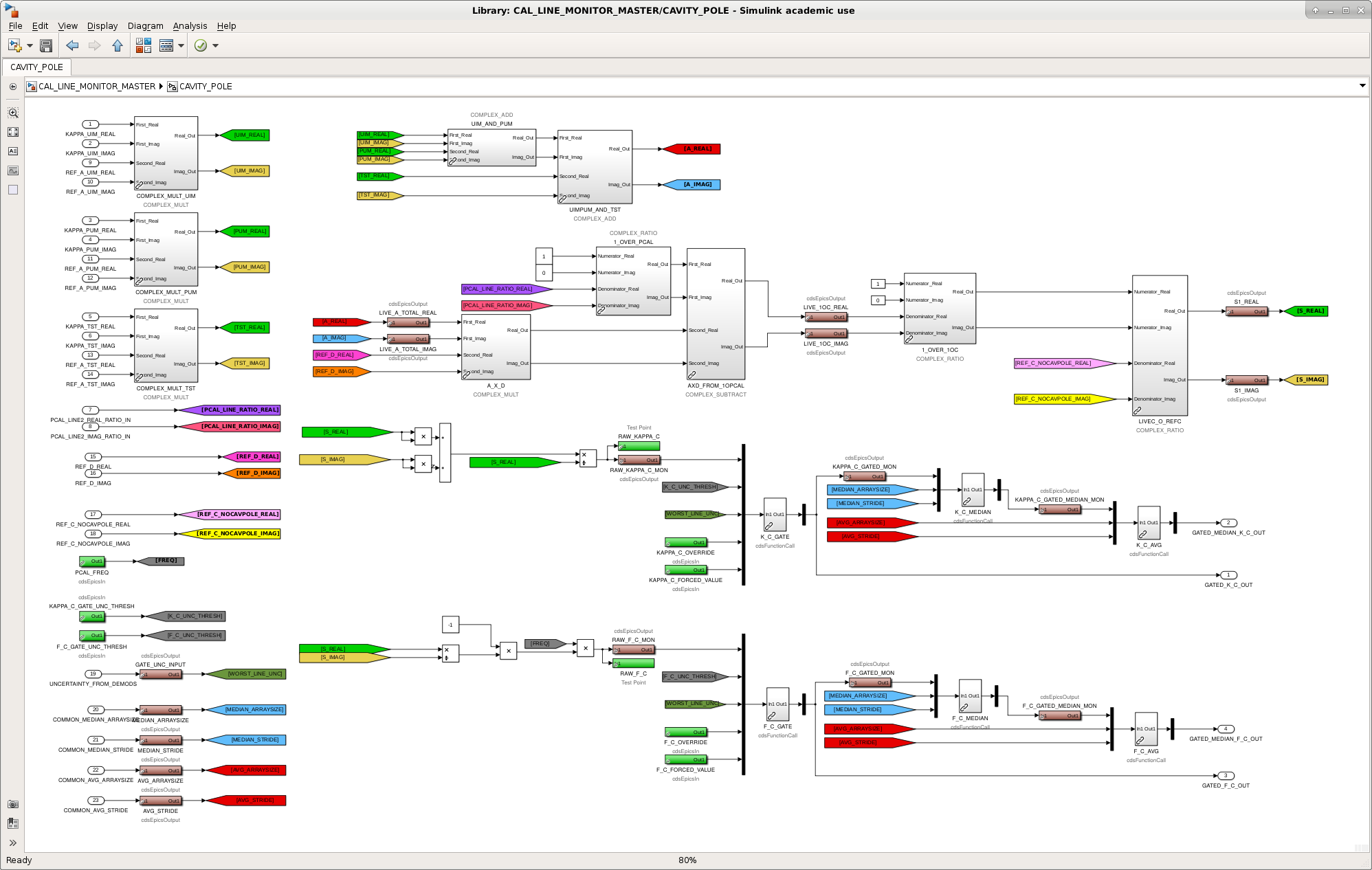
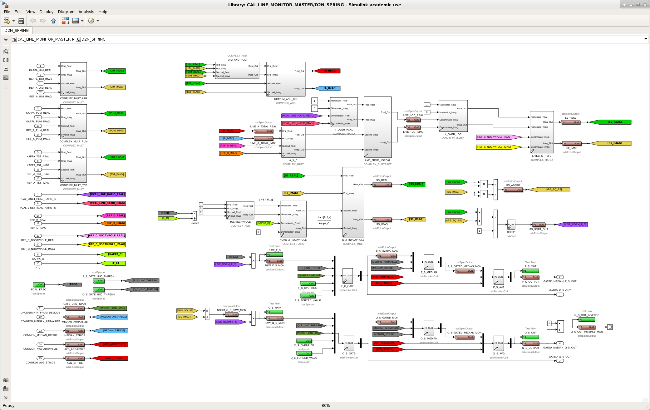
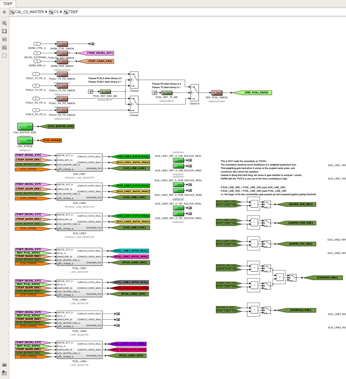
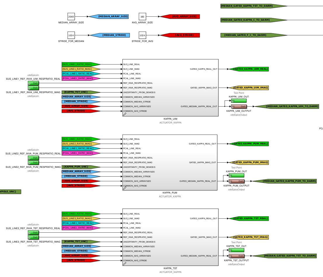
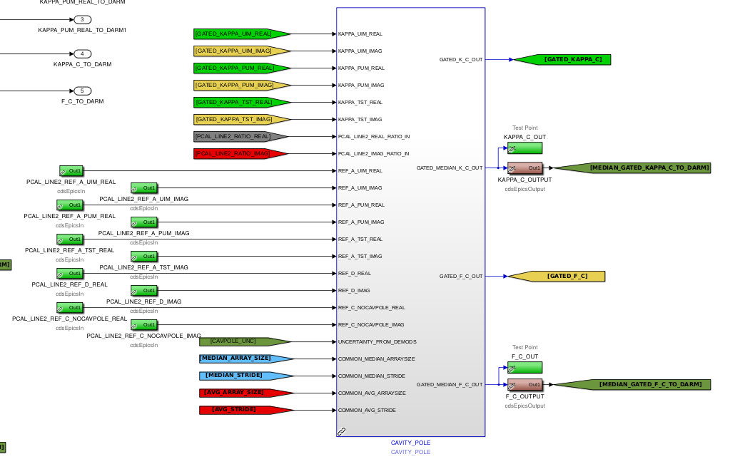
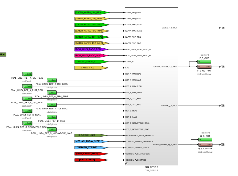
J. Kissel WP #8028 After in-depth investigation, Shivaraj and Saravanan ("S and S") discovered I had made a rather insidious mistake in the calculations for the time-dependent correction factors (TDCFs) for the DARM loop's optical plant. See LHO aLOG 46135 for the full story, but the message is that -- because of poorly labeled basic complex algebra blocks and my lack of careful checking -- I had inserted a multiply when I should have inserted a divide when computing a ratio in the middle of the calculations of kappa_C, f_c, f_s, and Q_s. The bug has been fixed, the model has been compiled, and the plan will be to install it tomorrow when everything is rebooted to upgrade the EEPROMs of all dolphin front-ends (see WP #8030). In detail, I've done the following: (1) I've extracted the D2N_SPRING block from the CS/TDEP level of the IFO generic corner station calibration library part, /opt/rtcds/userapps/release/cal/common/models/CAL_CS_MASTER.mdl and placed it inside the /opt/rtcds/userapps/release/cal/common/models/CAL_LINE_MONITOR_MASTER.mdl to be consistent with what's done with the ACTUATOR_KAPPA and CAVITY_POLE library blocks. Once created as a library part in CAL_LINE_MONITOR_MASTER, I then copied it back into the CS/TDEP subsystem, now as a link to library block in LINE_MONITOR_MASTER. This change is solely for consistency with how things are done for every other TDCF; it does not affect any functionality. (2) In the common library /opt/rtcds/userapps/release/cal/common/models/CAL_LINE_MONITOR_MASTER.mdl I've added a "Description" under the "General" tab of every block's "Properties" pop-up window (opened by right-clicking on the block and selecting "Properties..." from the right-click menu) that is identical to the library block's generic name. Further -- switching over to the "Block Annotation" tab -- I selected the Description property token and put it on the list of text and tokens for annotation. This means that now any time the block is copied from the common library to where it will be used in practice, it will retain an annotation/label showing its basic generic function, even if the block's name is changed. This is especially important for the complex algebra blocks which are used repeatedly all through out a given subsystem level and thus requiring a block name change (hence my mistake that S and S discovered). This change is solely for clarity, and doesn't affect any functionality. (3) I slowly and carefuly re-copied and re-linked all uses of these basic algebra parts into the greater library parts for the ACTUATOR_KAPPA, CAVITY_POLE, D2N_SPRING, LINE_MONITOR (for PCAL_LINE demodulation), and SYNCED_LINE_MONITOR (for SUS_LINE) in the common library /opt/rtcds/userapps/release/cal/common/models/CAL_LINE_MONITOR_MASTER.mdl During this step, I fixed the bug that Shiva and Saravanan identified by replacing the complex multiply with a complex ratio to correctly take the ratio of live C and C_res at the tail end of the computation of S in the CAVITY_POLE and D2N_SPRING library blocks. (4) I re-copied and re-linked all uses of the greater library parts in to the CS/TDEP generic corner station calibration library part, /opt/rtcds/userapps/release/cal/common/models/CAL_CS_MASTER.mdl New screenshots of everything are attached, and all changes the two, above-mentioned, libraries have been committed to the userapps repo.
These changes were installed on Jan 08 2019. See LHO aLOG 46291.
On 19 Dec, the first anemometer (H1:PEM-X_FENCE_WIND_SPEED_3) behind the fence was lower to 2'AGL (above ground level.) We want to know what the wind does in the gap between the ground and the bottom of the fence which is at 4'AGL; it is possible the wind could be accelerated in the gap.
Based on the data looked at this morning, the wind is not accelerated in the gap.
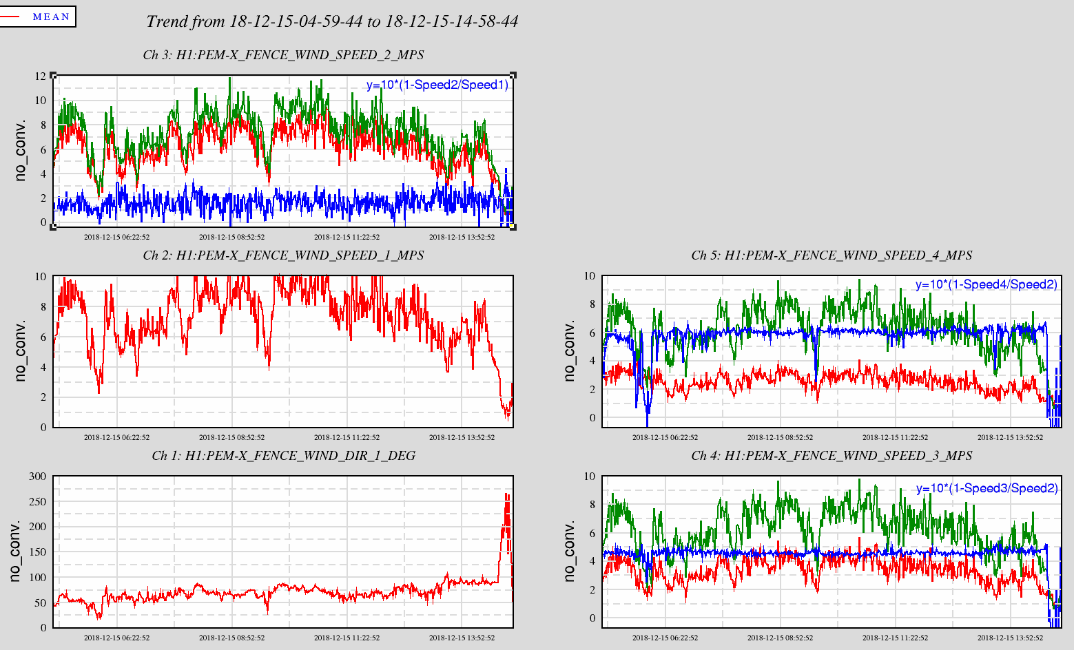
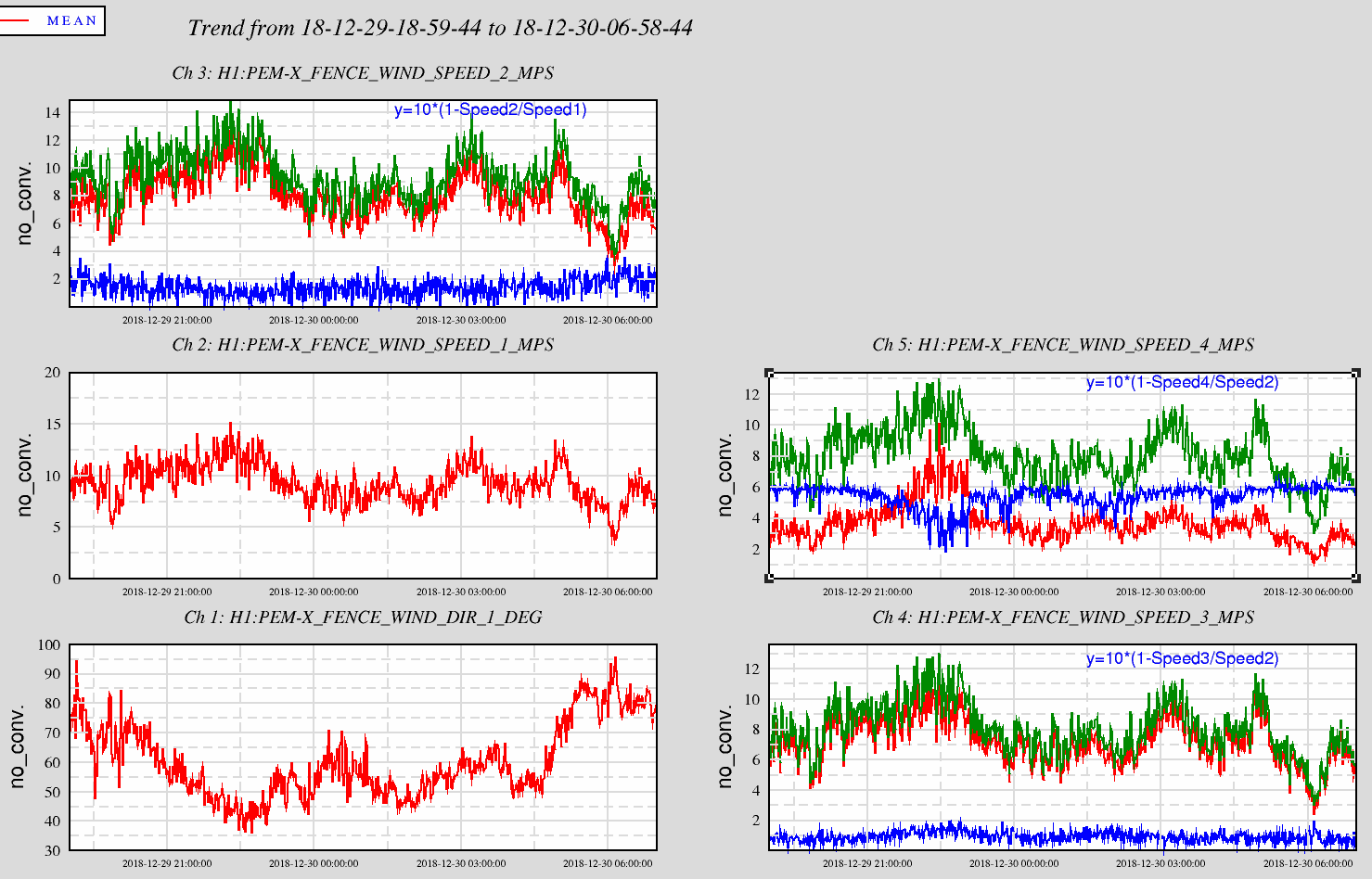
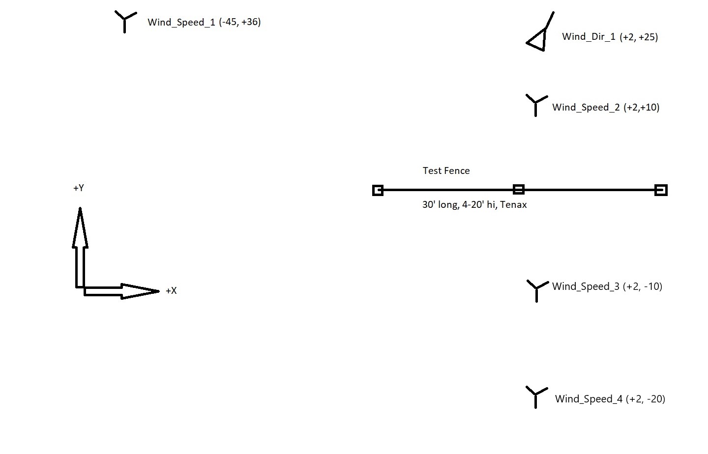
Attached are two graphs each with 5 plots showing the wind direction; and, the velocity at 4 locations, see location sketch here. On three of the speed plots are copies of another location's wind speed (in green); and, in blue, manipulated data as indicated in text. The blue trace scales from 0 to 10 for 0 to 100% speed reduction. Were there a velocity increase, the result would be negative.
The first attachment is from 15 December, a few days before the anemometer was lowered. The wind direction during these 10 hours was okay at worse being maybe 40° from our nominal 90. The upper left plot shows that there is a reduction of about 10 to 20% from the far field sensor to the unit 10' up-stream of the fence. The two right plots indicate that the fence is reducing the wind velocity about 45 to 60% with speed_4 showing the 60% reduction at 20' downwind compared to just 45% at 10' downwind, interesting...
The second attachment is from December 29/30 when for 12 hours the wind was strong and about in the right direction. Again a similar reduction at the upwind sensor relative to the free stream. The two right plots show the difference with the Speed3 lowered, While the Speed4/Speed2 ratio is still ~60%, there is only ~10% reduction down in the gap at Speed3. Note--10% reduction, no increase seen in this data set.
Caveat, two different data sets, different wind speeds and directions. But, given the reductions seen, especially further downstream at Speed4, I'd say the reduced reduction and no increase in Speed3 is legit. Will look at reasonably oriented stronger winds when they occur.
Seems like the upshot here is no acceleration in the vertical gap between the windscreen and the ground, therefore no motivation to install windscreen closer to the ground in any "production" wind fence.
Trends all look normal.
TITLE: 01/07 Day Shift: 16:00-00:00 UTC (08:00-16:00 PST), all times posted in UTC
STATE of H1: Commissioning
OUTGOING OPERATOR: None
CURRENT ENVIRONMENT:
Wind: 10mph Gusts, 6mph 5min avg
Primary useism: 0.03 μm/s
Secondary useism: 0.49 μm/s
QUICK SUMMARY:
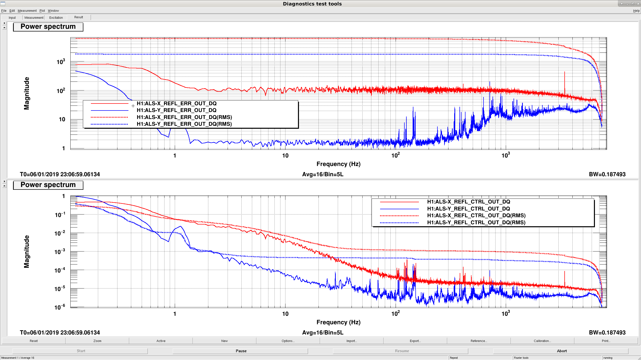
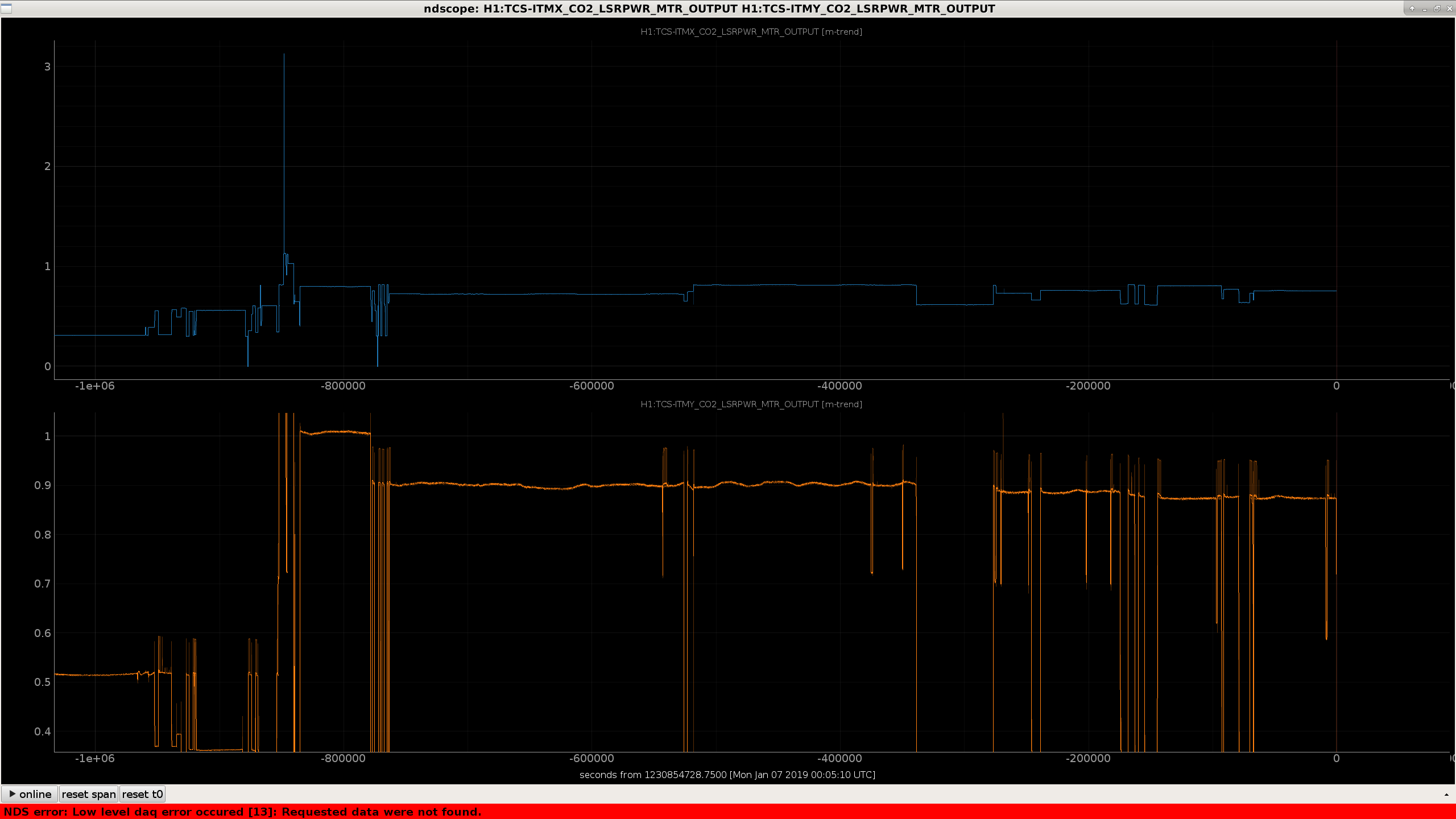
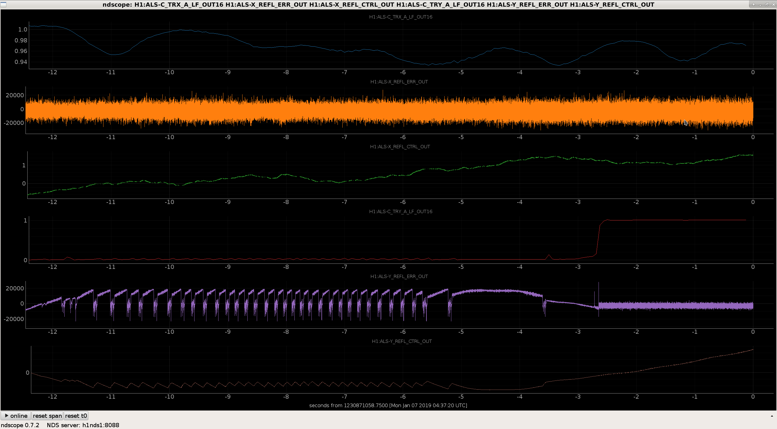
- After the last lockloss from last night, the EY Senscor gain became bad. After the earthquake this morning, I requested MORE_WINDY seismic conf (winds were ~30 mph) and this fixed EY. - I locked the Y arm after 5 hours. -- 3 hours of earthquake -- 1 hour of getting through INITIAL_ALIGNMENT -- 1 hour of getting a decent arm and TMS alignment after earthquake. -- Attachment 1 shows a 60 Hz peak on the ALS Y REFL B LF spectrum. I don't think ALS REFL B is used for locking, but this huge peak could find it's way into the Y locking loop somehow. -- Attachment 2 shows the ALS X and Y Arm PDH Spectra after locking today. The ctrl signals are calibrated into um. -- The Y arm is known to be extremely sensitive to misalignment, and prone to flashing though higher order modes even when well-aligned. Watching the X and Y arm error and ctrl time series, the Y error signal saturates at a much lower value than the X arm (the ctrl signal for Y can only go to +-1 um away from 0 before the controller runs out of range, while the X arm can go up to +-4 um). Then again, the X arm RMS is far higher. -- I included a screenshot of what the Y error and control signals are doing when Y acquires (attachment 4). Each error signal saturation is associated with the quick flashes we see in the control room. The Y arm seems to be swinging around too much, and the Y PDH can't keep up. - Going through INITIAL_ALIGNMENT, the ACQUIRE_PRX state immediately railed the PRM M3 stage since we had fallen off the POP A QPD. I had to pitch PRM M0 manually to get PRX to lock. When it did lock and get through PRC_ALIGN, the alignment onto POP_A QPD was pitched to -1. Also had to manually align SRY. -- I was unable to hold a DRMI lock for more than two minutes. and when I did POPAIR 18 was way down with good alignment (~50 cts). All last week we could get to 65 cts. Still cannot figure out why POPAIR18 is so low. -- At least four times, I have acquired DRMI, sat in ENGAGE_DRMI_ASC for two minutes, then lost lock. -- To see if it is MICH ASC that is unstable I requested TURN_ON_BS_STAGE_2. So far I've been locked for 15 minutes here, so the MICH ASC is likely causing DRMI locklosses. -- The MICH ASC was causing locklosses, but only because the SRM alignment was very bad. Touching up the SRM alignment allowed us to stay at ENGAGE_DRMI_ASC indefinitely, but did not improve POPAIR18 levels. -- TRANSITION_DRMI_TO_3F caused MICH Pitch to ring up with it's current gain of -0.25. I caught it without losing lock by changing the gain to -0.12. -- Was unable to go past DHARD_WFS. -- I checked the TCS settings, and while they aren't perfect (see below), there is no egregious problem (ring heaters and C02 are at at least close to their requested values, ITM spherical power is close to what it was yesterday) - The ITMY CO2 laser is not lasing at the power requested, causing the TCS_ITMY_CO2_PWR guardian to be broken. It wants to get to HOLD_POWER but keeps stalling in ADJUSTING_POWER. -- The requested power for ITMY is 1.0 W, but the CO2 is only delivering 0.87. This is beyond the acceptable range of 0.08 W, so ADJUSTING_POWER continually requests ADJUSTING_POWER over and over, stalling every time. -- Attachment 3 shows this changed occurred at Dec 28 2018 23:25:10 UTC, so it should not be a major problem for locking. More disturbing is the fact that the ITMY CO2 power appears to be decaying slightly. -- I don't know how to fix the CO2 laser to actually lase at the correct power output, so I changed the requested power to 0.87 W so that ISC_LOCK doesn't have to unstall TCS_ITMY_CO2_PWR every two seconds. - It seems that I have been hoisted by my own petard. After initial alignment, I was given an significantly different alignment than usual. My manual alignment to get PRX and SRY to lock took us completely off the rails, too far for the initial alignment ASC loops to correct for. -- I tried using wfsreliefpast.py at a time for Georgia's lock last night, but this took me too far off to lock at 2 W. I used mygoToAlignment.pyin/opt/rtcds/userapps/release/asc/common/scripts/at GPS 1230783828 to move the sliders, this brought me close enough to get INITIAL_ALIGNMENT running again. - Again, locking ALS Y has proven extraordinarily tedious (~1.5 hours of Y arm alignment). -- I lowered the Y arm acquisition gain to -10 dB from -4 dB, this changed nothing. -- For future reference, watching the height fast flashes of H1:ALS-C_TRY_A_LF_OUT_DQ on ndscope made actually aligning possible, since the Y arm likes to grab onto HOMs for 99% of the time, even with good alignment. - Made to back to RESONANCE with POPAIR18 back to ~60 cts. ENGAGE_REFL_POP_WFS murdered the lock. ENGAGE_ASC_FOR_FULL_IFO murdered the next lock. -- The next lock, I aligned CHARD by hand using Hang'smove_ARM_dev.pyscript, then ran ENGAGE_ASC_FOR_FULL_IFO, which almost worked this time. PRC1 rung up late in the FULL IFO alignment. -- After this lockloss I was unable to lock ALS DIFF anymore: three ringups killed three locks in a row. -- The ALS_XARM guardian died (?), halting ISC_LOCK with Ezca connection issues. Restarted withguardctrl restart ALS_XARM. It is in this regrettable state I must leave the interferometer: broken ALS Y, broken ALS arms to DIFF transition, poorly aligned, and ASC that cannot converge without killing the lock.
The reason that the CO2_PWR Guardian is continually trying to adjust the power but failing, is because the rotation stage(RS) calibration is off. We've noticed that this will drift off from time to time and will need to be updated. Searching for home on the RS can sometimes help a bit (there is a Guardian state that will do it for you), but it has to fully rotate the RS so keep in mind that you will blast the optic with a good amount of power for a minute or two.
| Frequency (Hz) | LO actuator | Demod actuator | |
| Yaw1 | 16.131 | SRM | - |
| Yaw2 | 17.37 | PR2 | - |
| Yaw8 | 23.25 | CHARD | - |
| Yaw9 | 21.11 | CSOFT | - |
| Yaw3 | 18.37 | PRM | PRM |
| Yaw4 | 22.347 | EX | IX, EX |
| Yaw5 | 21.9 | EY | IY, EY |
| Pit3 | 19.653 | PRM | PRM |
| Pit4 | 20.131 | EX | IX,EX |
| Pit5 | 20.789 | EY | IY,EY |
The L1 ASC dither frequencies are all in the range of 6-9 Hz. Why were the H1 dither frequencies set so much higher in the first place?
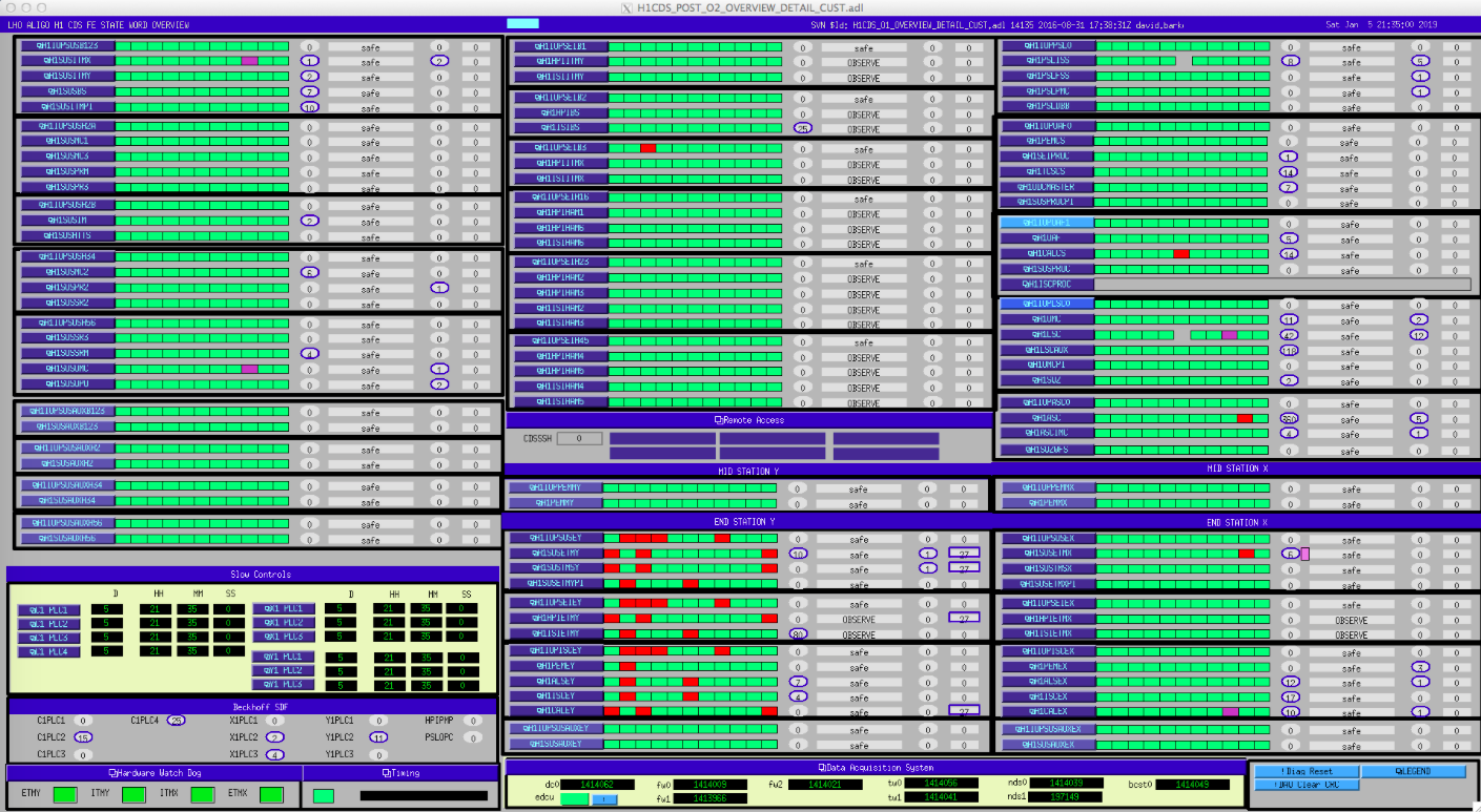
EY has had a Dolphin crash. I'm restarting the models.
I've opened FRS12076
I took dolphin diagnostics before restarting. comparing Sat 5 Jan with Tue 25 Dec scans shows that an error appeared on h1iscey in this case.
## h1iscey ##################################################### 8c8 < Date : Sat Jan 5 21:39:45 PST 2019 --- > Date : Tue Dec 25 10:07:36 PST 2018 44c44 < Link 0 uptime : 3982458 seconds --- > Link 0 uptime : 2995486 seconds 56c56 < Chip temperature : 77 C --- > Chip temperature : 75 C 102,135d101 < **************** PCIe SLOT ERROR INFORMATION FOR ADAPTER NO 0 **************** < < NACK error cnt - PCIe Slot .................... : 1 < NACK DLLP transmitted ......................: 1 < NACK DLLP received .........................: 0 < < Total uncorrectable error cnt - PCIe Slot ..... : 0 < dlperr cnt ................................ : 0 < sdoenerr cnt .............................. : 0 < poisoned cnt .............................. : 0 < fcperr cnt ................................ : 0 < compto cnt ................................ : 0 < cabort cnt ................................ : 0 < uecomp cnt ................................ : 0 < rcvovr cnt ................................ : 0 < malformed cnt ............................. : 0 < ecrc_cnt .................................. : 0 < ur_cnt .................................... : 0 < acsv_cnt .................................. : 0 < uie_cnt ................................... : 0 < mcblktlp cnt .............................. : 0 < atopeb cnt ................................ : 0 < tlppbe cnt ................................ : 0 < < Total correctable error cnt - PCIe Slot ....... : 1 < rcverr cnt ................................ : 1 < badtlp cnt ................................ : 1 < baddllp cnt ............................... : 1 < rplyrovr cnt .............................. : 0 < rplyto cnt ................................ : 0 < advisorynf cnt ............................ : 0 < cie cnt ................................... : 0 < hlo cnt ................................... : 0 <
Sheila, Nutsinee
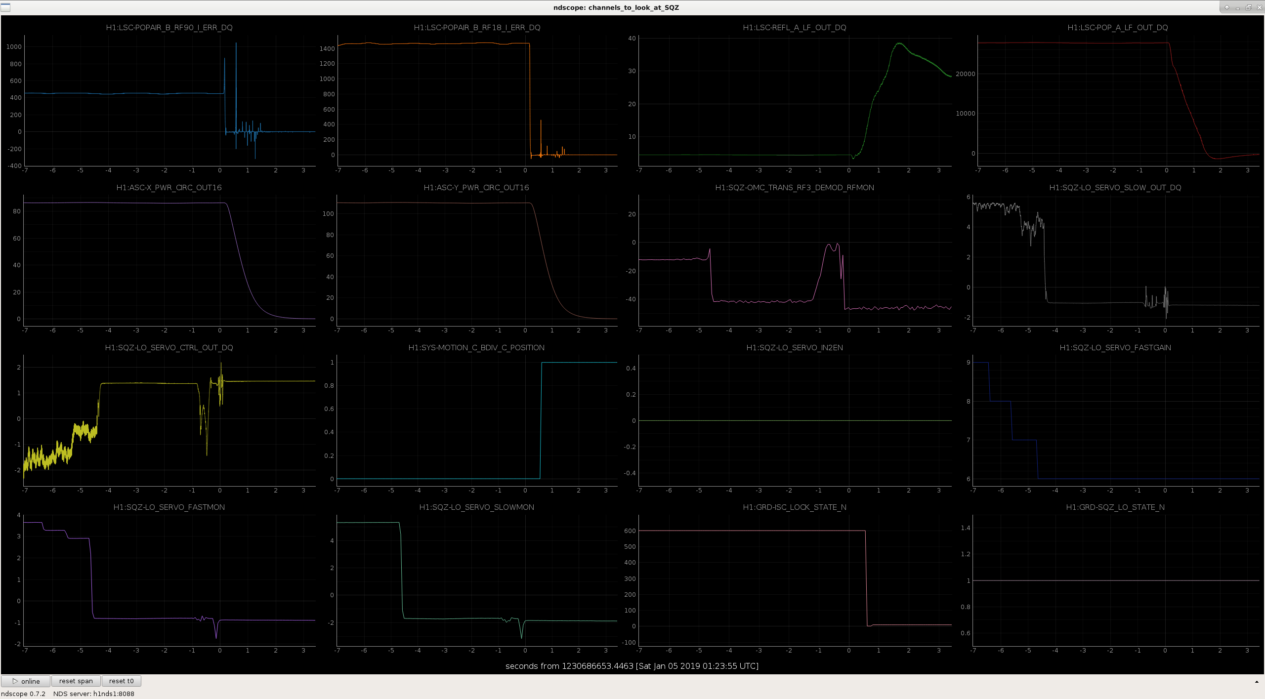
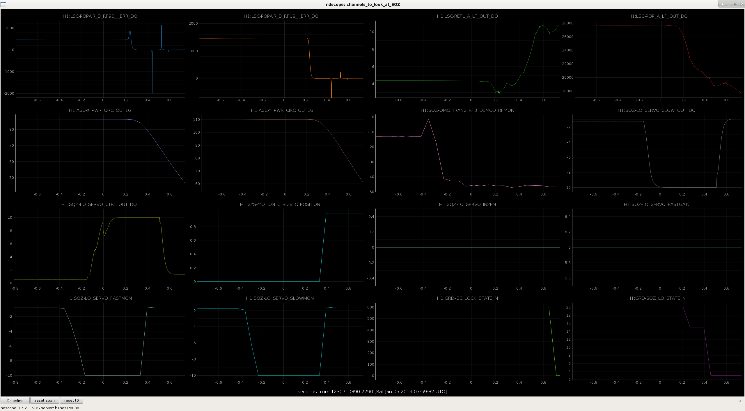
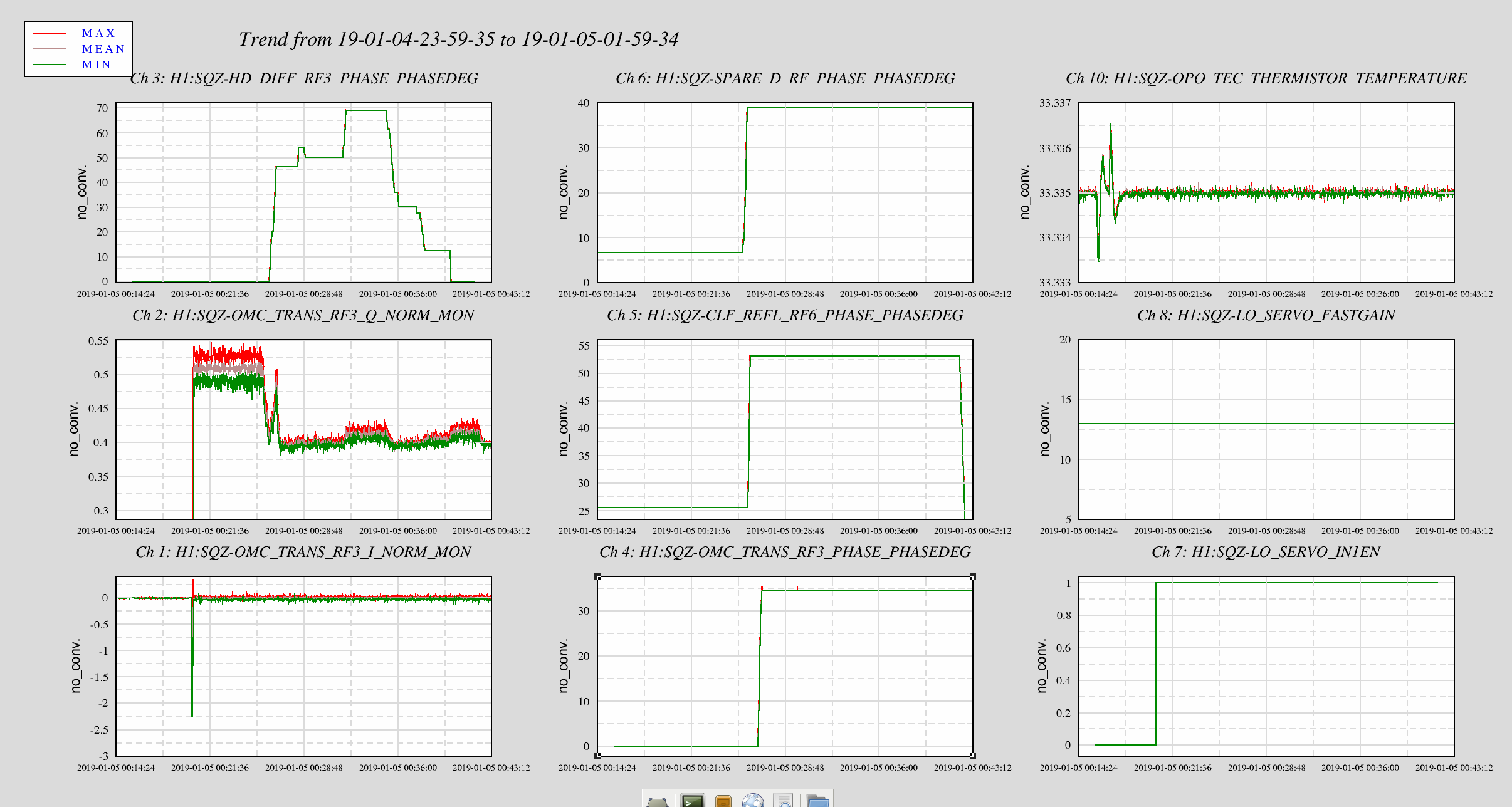
We made a two attempts to inject squeezing today, both times we eventually unlocked the interferometer when the LO servo unlocked. These two locklosses happened at 7:59 UTC and 1:23 UTC today.
We've made some improvements to the automation.
I think looking at LO output and close the shutter when it rails isn't fast enough. We need to look for a pending doom, like a drop in 3MHz signal or error signal. We need a fast channel for this to be able to close beam diverter in time when something goes wrong.
Attached are plots of these two locklosses.
In the first one, the OMC RF3MHz signal drops 4 seconds before the lockloss. We had been checking the LO SERVO fastmon and shutting the beam diverter if it reaches the rails, but this wouldn't have caught either of these LO locklosses. I've changed the SQZ_LO guardian so that it will close the beam diverter if the RF3MHz drops below 20dBm, which would probably have prevented the first of these locklosses. This might not be fast enough to catch locklosses like the second one.
Not relate to this topic. But for the record, Jan 4th was the day we injected squeezing and didn't see anything. We looked into the nlg during the time as we changed 6MHz and 3MHz using Q error signal and turned out we only had nlg of 1.3. This could explain why we didn't see much.
[Keita, Jenne]
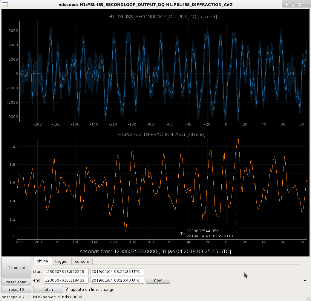
Keita and I have been trying to figure out what is going on with the ISS that is causing the diffracted power to oscillate so largely the past few days. When the IMC is locked, the ISS first loop, with the slow part of the second loop board but not the "second loop" as you would normally think of it, is causing the diffracted power to oscillate more than 1.5%. This is very large compared to what it ought to be.
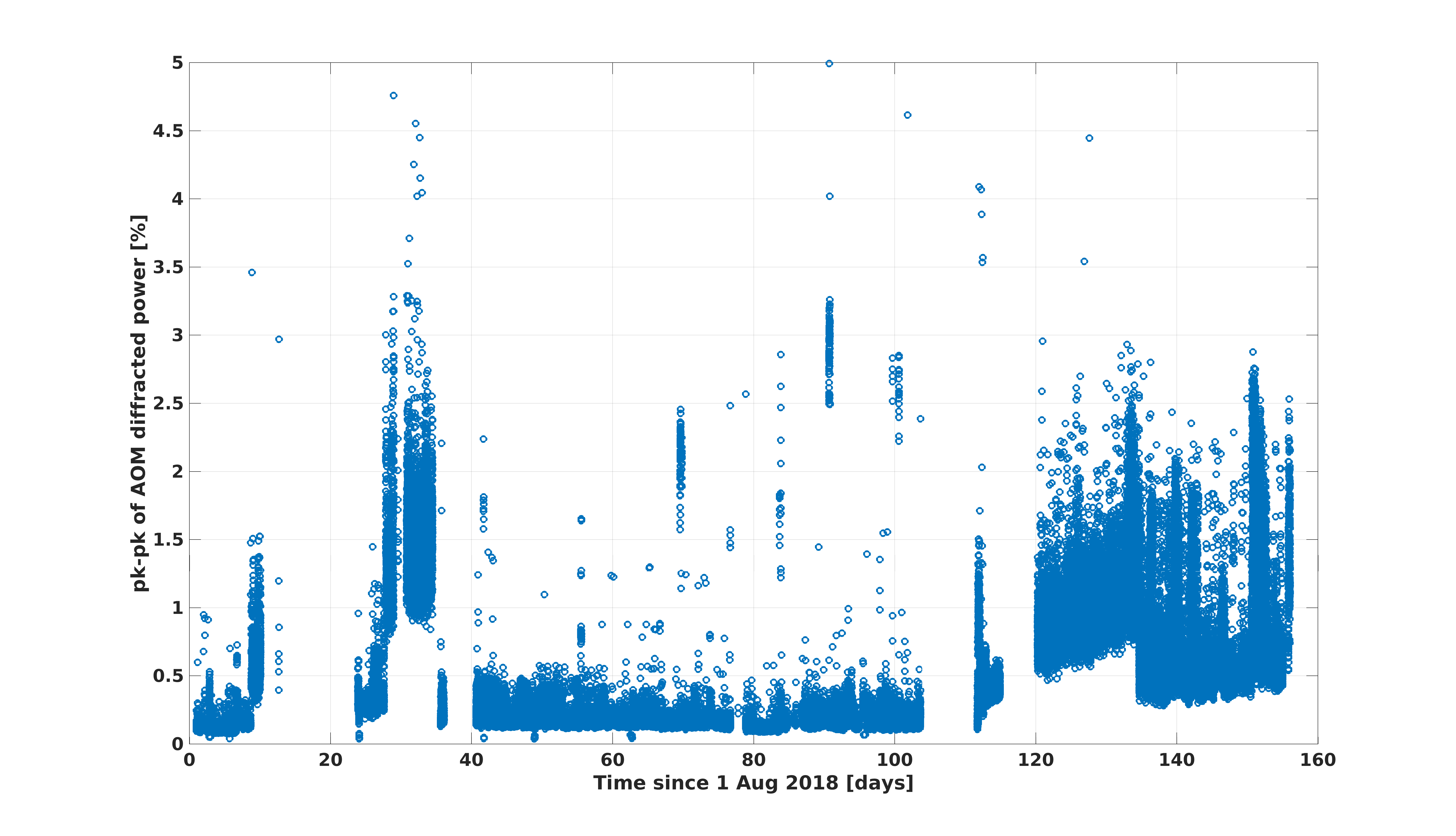
In the attached plot, I have the peak-to-peak values of the diffracted power, from August 1st 2018 through yesterday. I'm using the max and min of minute trends, so this won't catch if some short period of time has a small pk-pk value, but will see larger trends. Data is only plotted here if the first loop is closed, the second loop is open, but the second loop is sending signal from the slow loop over to the first loop (yes, the ISS is confusing...). That is, this should represent times when the IMC is locked, or we're trying to acquire IFO lock, but not times when the second loop is actually feeding back using IMC transmitted power (this is engaged in guardian once DRMI is locked).
You can see that there was a time in ~September that the diffracted power oscillations were high, but then they got better. Since the beginning of December, the peak-to-peak value hasn't been near it's normal small value.
It seems like the second loop board is picking up more noise somehow, somewhere, and is feeding that through the slow portion of the board to the AOM. When we turn off the output of the second loop board, we immediately see that the diffracted power becomes nice and smooth and quiet (we tried this briefly yesterday). Still under investigation, but something is definitely not right.
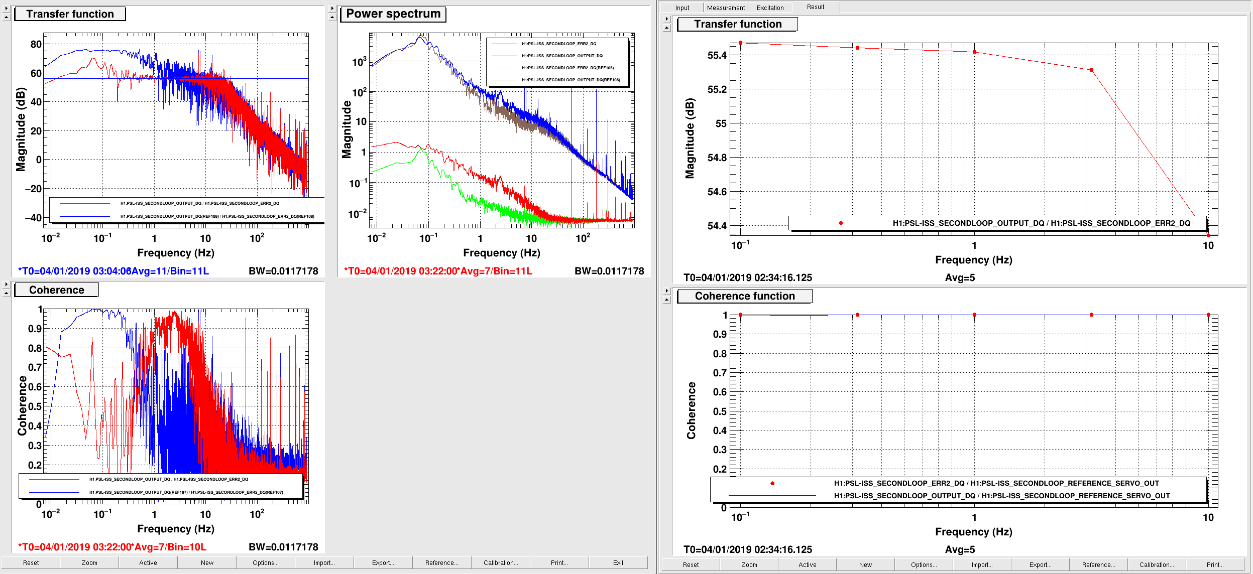
First attachment shows that the 2nd board output is pushing the 1st loop board when both the output switch in the 2nd loop board and the 2nd loop enable switch in the 1st loop board are on, even when the 2nd loop itself is open and even when slow offset servo is off, i.e. even when the 2nd loop output is entirely driven by the noise of the board itself. (The plot was taken when the slow offset feedback was on but the 2nd loop was off, but slow offset on/off doesn't make much difference if at all.)
Second attachment shows that the board is either generating or picking up some noise at around 0.1Hz downstream of ERR2, driving the board output. Let me explain.
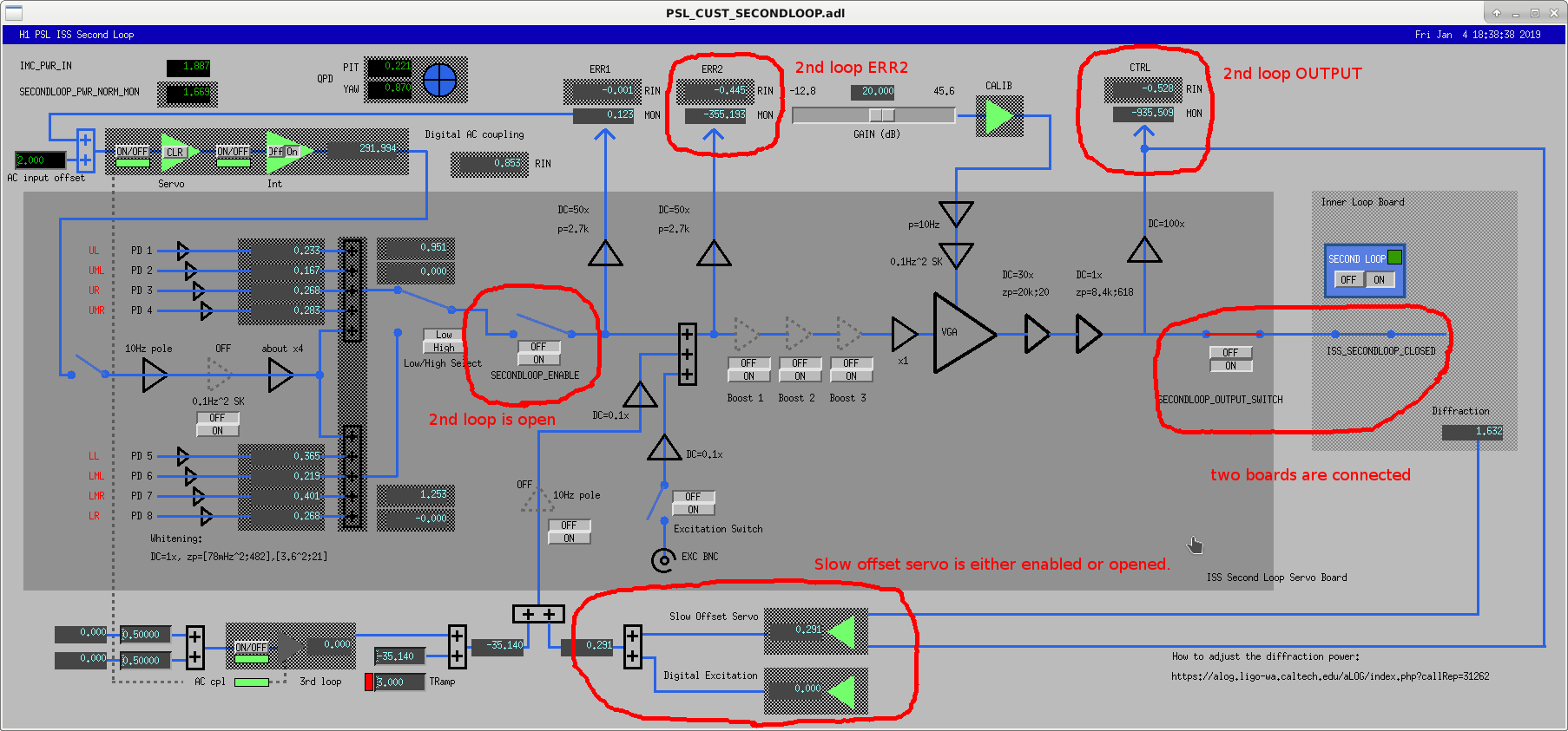
On the left is the non-driven noise transfer function from ERR2 to OUTPUT. ERR2 is the error point readback downstream of the summation point for the slow offset feedback. Live and ref traces show the slow offset feedback on (live) and off (ref). See the third attachment to see the board configuration and to understand which channel is what.
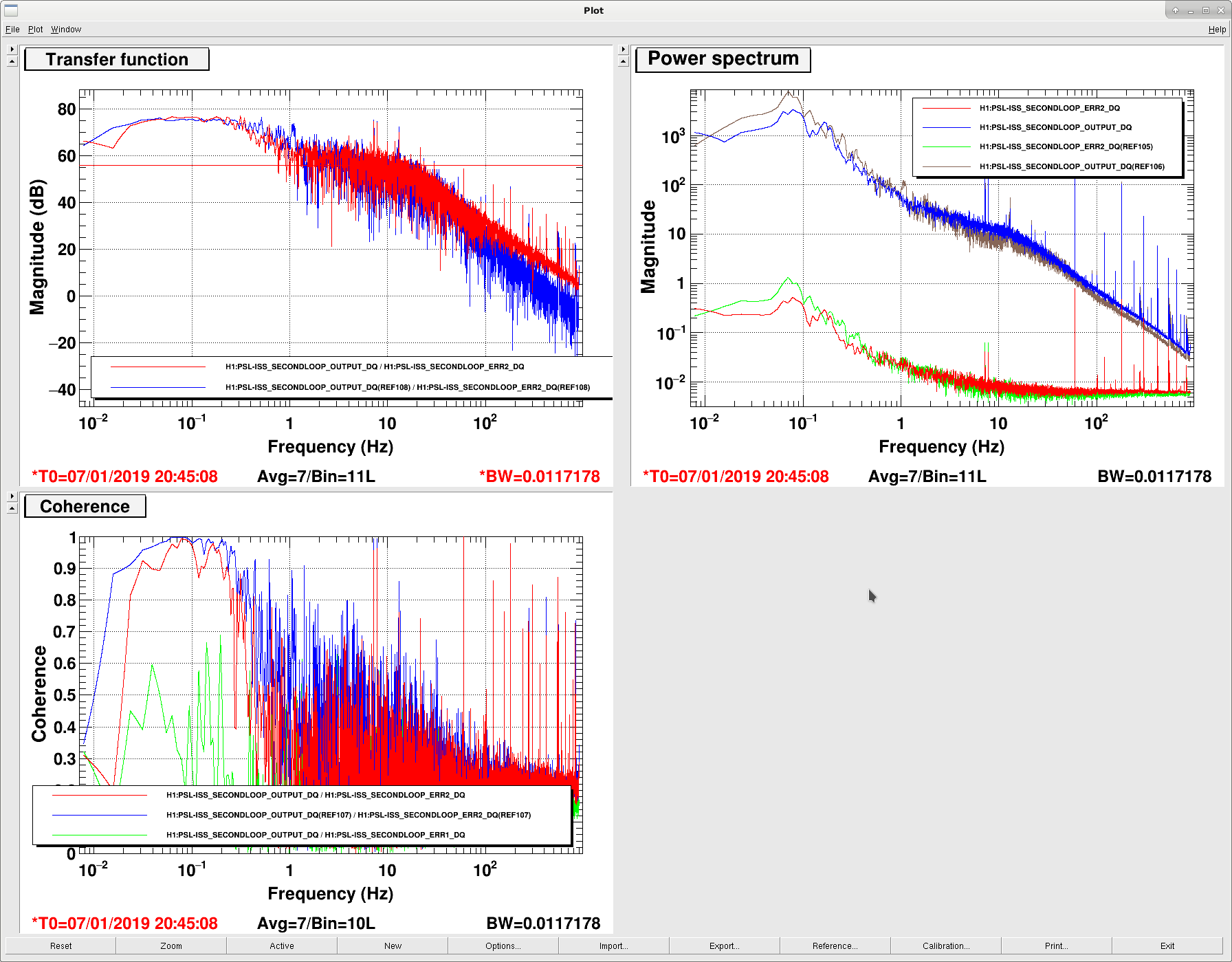
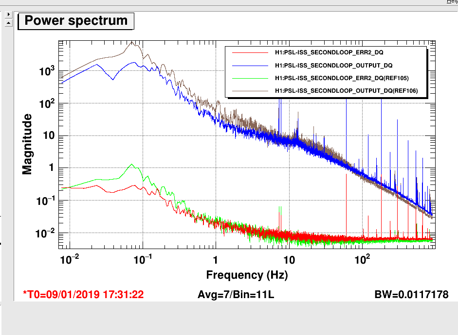
Without slow offset feedback(left of the left plot, blue), the coherence at 0.1Hz is almost 1, but the transfer function, which is supposed to be 56dB for f<20Hz, is about 20dB larger than it should be.
With slow offset feedback (red), the coherence at 0.1Hz goes down but instead the coherence becomes high at a few Hz, and where the coherence is high the transfer function is 56dB (red). That's because the board output didn't change for f<0.5Hz or so with or without slow feedback (right top panel of the left plot), but ERR2 increased for f<10Hz when slow offset feedback was on, and this was also visible in the board output in [1, 10] Hz.
When you make a driven TF even when slow feedback is on (right of the left plot) it was right at 56dB, though.
All these mean is that ERR2 (when slow feedback is off) and OUTPUT see the same noise peaking at 0.1Hz (because coherence is 1) and that the noise cannot be present in the board upstream of ERR2 i.e. summation point output (because TF is not 56dB). The noise in OUTPUT is a real problem and it seems to have become worse recently, judging from people's complaint.
Noise in ERR2 is probably not a real problem as that is not causing the OUTPUT to swing, at least not as of now. ERR2 monitor is merely picking the same noise somehow, quite possibly it's picking up the OUTPUT directly.
I don't have any explanation for the noise shape peaking at 0.1Hz.
[Daniel, Keita, Jenne]
Marc and Richard are looking into whether we have a spare ISS Second Loop chassis (it sounds like we do), to swap in. The output of the current board is drifting a lot, about 30mV pk-pk (it's roughly 10,000 counts that we are seeing on the monitor, which translates to about 30mV at the actual board output once you take the 100x gain of the monitor into account).
This noise is being introduced between the 1st and 2nd boosts. Engaging either boost 2 or boost 3 seems to amplify the noise, and the output (H1:PSL-ISS_SECONDLOOP_OUTPUT_MON) moves by a huge amount. However engaging only boost 1 does not amplify the noise. With only boost 1 engaged, the offset is increased as expected, but the pk-pk output drift is back to about 10,000 counts. We had also changed the output gain (H1:PSL-ISS_SECONDLOOP_GAIN) and saw that the noise is amplified by that gain. Since this gain is after the 3 boosts, we started working toward the input of the board, and tried engaging the boosts one at a time, as described above.
Keita had a look at the schematic (D1600298), and the current suspicion is that the switch for boost 1 is busted. Perhaps when we're requesting that boost 1 be off (bypassing the opamp stage), the switch is still a little bit connected to the output of the opamp stage, so we're getting weird feedback loops that shouldn't exist. This weird feedback loop could be how the error point monitor (H1:PSL-ISS_SECONDLOOP_ERR2_MON) is coherent with this noise, since that monitor is at the input to boost 1.
If we have a chance today (otherwise it'll happen tomorrow) we'll swap in the spare ISS second loop chassis, and can confirm the problem with the currently-installed chassis, and replace that switch.
Other observations are that if we significantly increase the gain of the slow reference servo, we can suppress the noise that is being introduced between the boost stages. However, that would mean that the reference servo is marginally stable, so we don't actually want to run like that. (And, anyway, we want to fix the problem, not just work around it). Also, Sheila and Keita were able to DC couple the ISS second loop on Thursday (alog 46229), and when the loop was DC coupled the noise was again suppressed.
For our current lock, we have the Second Loop board entirely disconnected from the First Loop board (switches H1:PSL-ISS_SECONDLOOP_OUTPUT_SWITCH_MON and H1:PSL-ISS_SECONDLOOP_CLOSED are both open).
So much for the broken switch theory.
I and Fil changed the chassis (old one: S1700062, new one: S1700063) but it seems like the noise didn't change much if any. In the attached, current traces are now and references are with the old board.
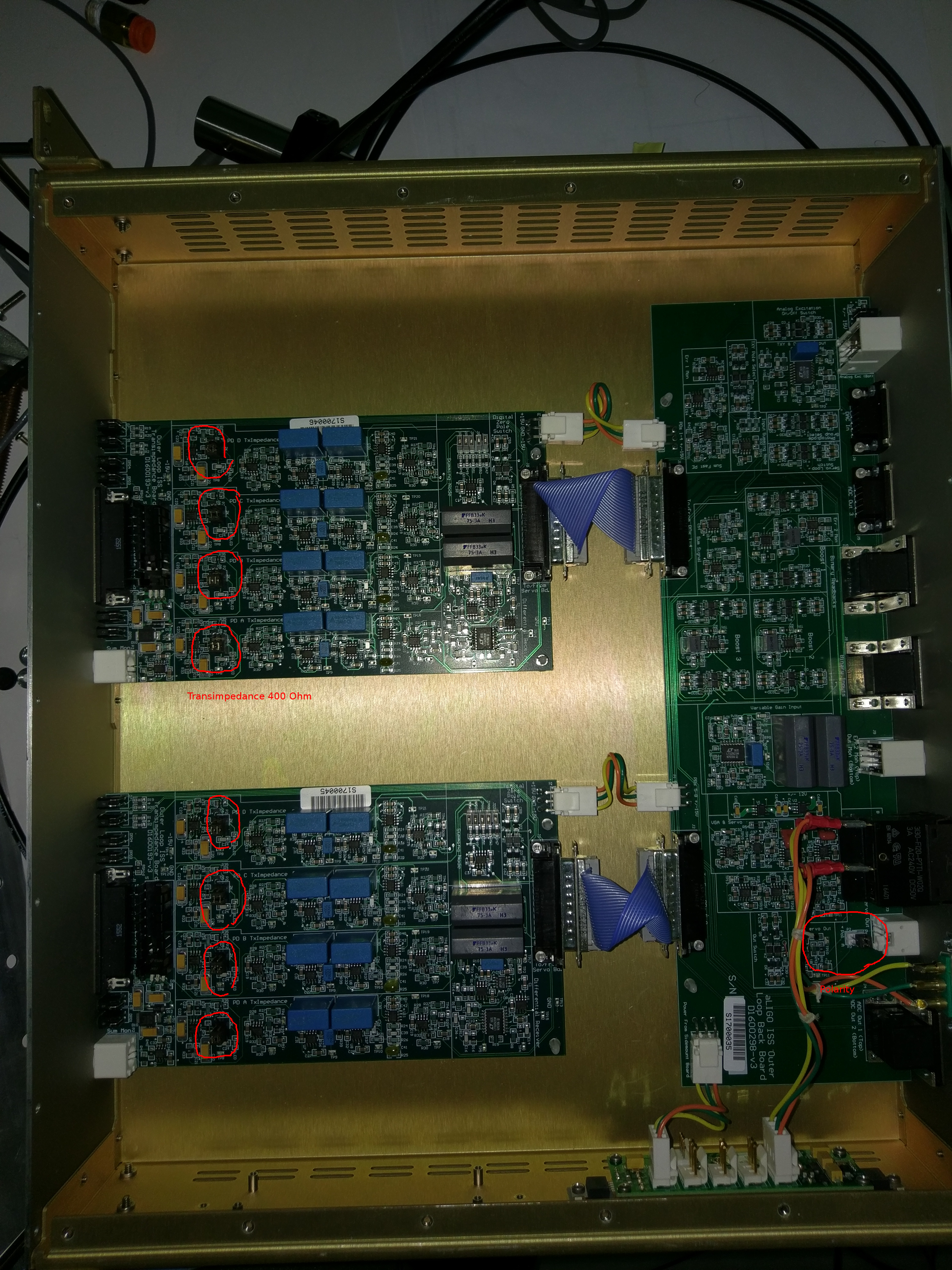
BTW, just for documentation purpose, attached is the photo of the boards with jumpers for correct transimpedance (400 Ohm) and output polarity.
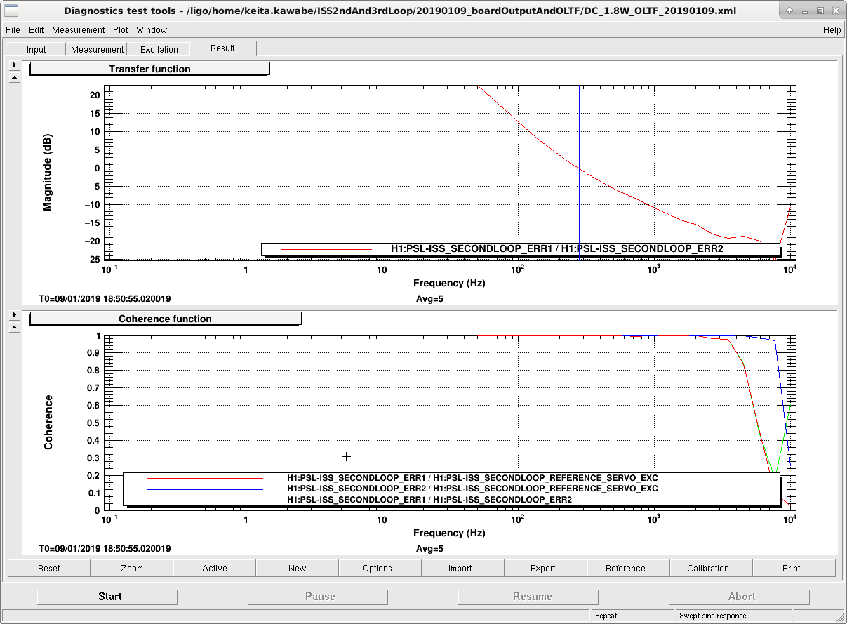
Note that the noise goes up and down on its own. Today at random time I measured the board output and the peak at 0.1Hz was much smaller than it used to be though it's not gone either (1st attachment).
Also as a side note, ISS 2nd loop gain is too small, though this is not related to the problem discussed in this thread (2nd attachment).
At 2W, DC coupled, no boost, with 20dB slider, UGF is about 280Hz, and the UGF will only increase to about 4.7kHz or so at 30W, but we should push it to 10 or 20kHz (that's what we did in O2).
Since increasing the slider before DC coupling will only worsen the problem discussed in this thread, we need to think about increasing the slider after DC coupling the loop.
Marc Daniel
The output offset shifts seen in the installed units cannot be reproduced in the shop. There, the unit seems to be at least 10 less "shifty."
We discovered an unused OpAmp in a 4 device package that wasn't connected to anything (U2B on D1600298). Not a good idea, since it could be oscillating and effect the devices in the same package.
Things to consider in D1600298: