jenne.driggers@LIGO.ORG - posted 17:22, Friday 04 January 2019 (46231)
Friday AM locking, IFO trigger threshold setting
- Alignment really bad, ran initial alignment.
- MICH_DARK_Align worked today (tried it on a whim, since it hadn't been working).
- PRC_Align needs to turn off the input limiter.
- ISS Second Loop offsets need to be adjusted. Trying to close second loop makes first loop lose lock. Commented out ISS in DRMI_CHECK_ASC for now.
- ALS was having trouble locking. Looked like DIFF glitches, of the style that happen when COMM and DIFF's frequencies cross. I by-hand requested COMM to go to HANDOFF_PART1 and the DIFF glitches seemed to go away. So maybe we want to at least partly lock COMM when we're working on DIFF, so that we don't get frequency crossings (if that's what is going on)?
- Can semi-repeatably lock ALS by requesting COMM to HANDOFF_PART1 and then requesting main guardian to LOCKING_ALS. But, at some point COMM and DIFF both see an oscillation at about 765 Hz (on a different lock it was more like 360 Hz - why??). This coincides in time with the Xarm green power dropping, which makes things worse, and then we lose lock. The COMM crossover with MC2 (measured by taking an In1/In2 TF of LSC-MCL) is nice and stable. The COMM OLG as measured by Craig also looks nice and stable, having a little more than 90 degrees of phase at about 750 Hz.
- Have also a few locks been okay just requesting LOCKING_ALS.
- Sheila is reverting to LOCKING_ALS setup back to a situation where we lock both COMM and DIFF at the same time.
- Trying to hold on to the arms in green stronger, Craig made the Yarm green PDH settings the same as the Yarm green PDH settings. This means that right now Yarm has 3dB less slider gain, but is using both boosts. The Yarm control signal doesn't seem drastically changed, but maybe the transmitted green power is a bit more steady.
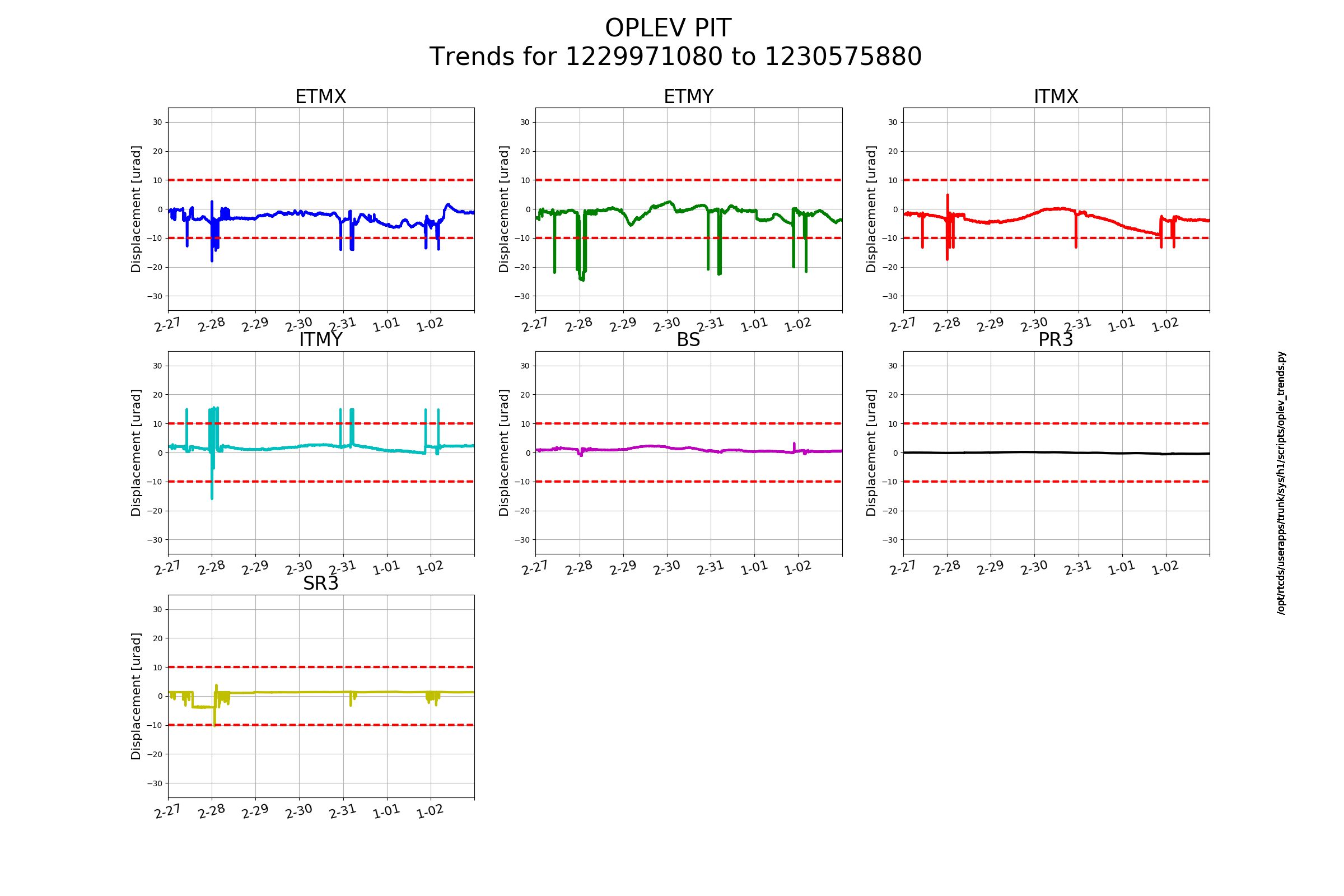
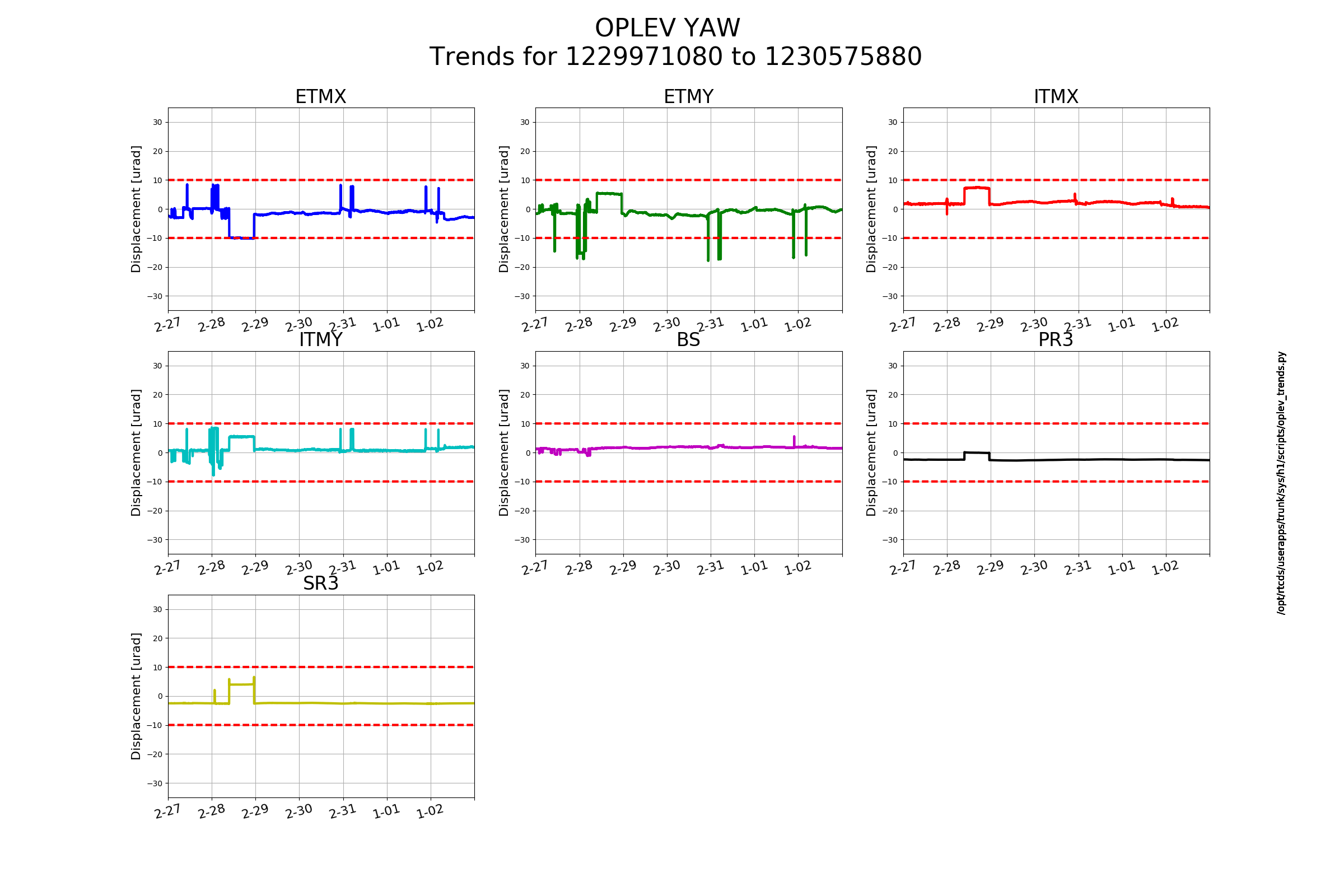
- Sometimes we are able to lock ALS, but the Xarm gets misaligned and we lose lock. Georgia and Sheila point out that because of the high ground motion, we seem to be pushing on the ETMX L1 stage pretty hard to hold the lock (fine). But, we have bad L2A coupling, so this large actuation on L1 is moving ETMX in angle.
- It looks, according to the oplev, like the L2P decoupling for L1 is fine, and ETMX isn't pitching too badly. But, the optic is yaw-ing a lot. We don't have any L2Y decoupling engaged for the L1 stage right now, but maybe we need to put that in, in order to handle these high ground motion times.
- It looks like the data for ETMX L1 was most recently measured in alog 43150. In the comments, Hang has done the fits to JeffK's data for L2P, but not for L2Y.
- Between ETMX L2Y tuning and the wind dying down, we are now again able to lock DRMI.
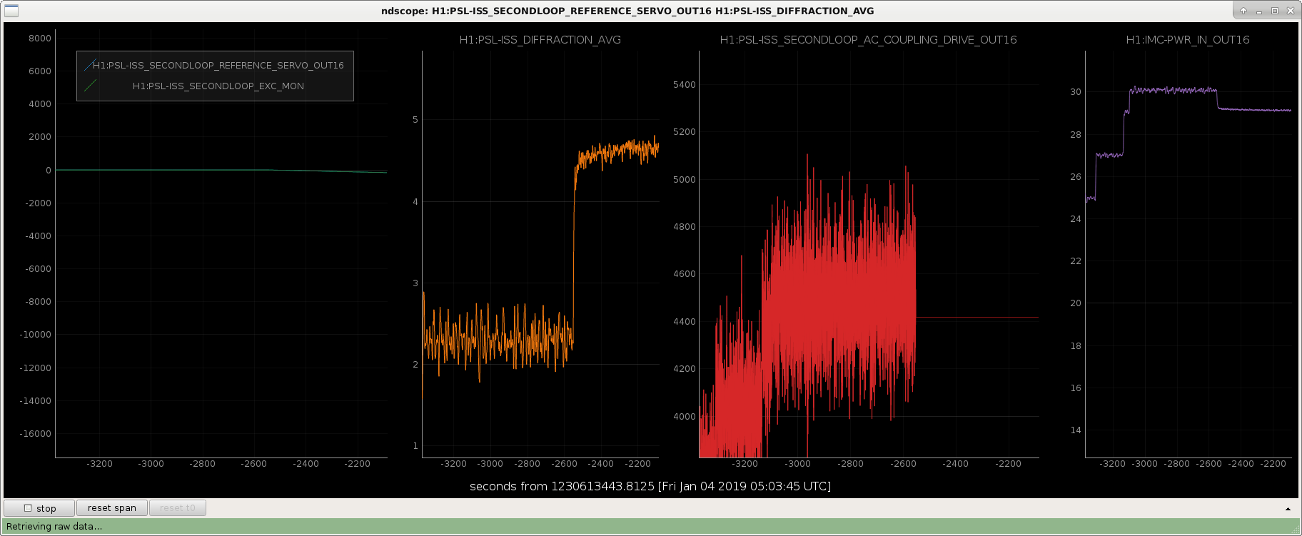
- ISS_ON state in IMC_LOCK guardian is killing the lock. There is definitely something wrong with the ISS second loop. For now, it's commented out of the guardian. (alogs forthcoming from me and Keita about the second loop acting weird).
- MICH ASC was also causing locklosses again. The AS36 phase needed to be tuned to match the new TCS settings. I added +60 deg of phase to each quadrant of AS36_A, and at least for this lock, MICH ASC hasn't caused any more trouple.
- Lockloss at the DC readout transition. Sheila says that she saw this at least once yesterday as well.
- Next lock the transition just worked on its own.
- Based on a plot from the 16.5 hour lock Wednesday night / Thursday morning, I have made the IFO lockloss trigger more strict.
- Once ASC is on and converged, normalized POP_A_DC never falls below about 950 counts. So, I have set in PREP_DC_READOUT_TRANSITION that the overall IFO trigger should shut things down if POP_A_DC falls below 850. This should leave enough margin in case the power dips for some unknown reason.
- Note: the long lock was at 20W injected, but now we're at 30W injected, and normalized POP_A_DC is closer to 910 counts, so the threshold of 850 should be okay, and actually be a little tighter.
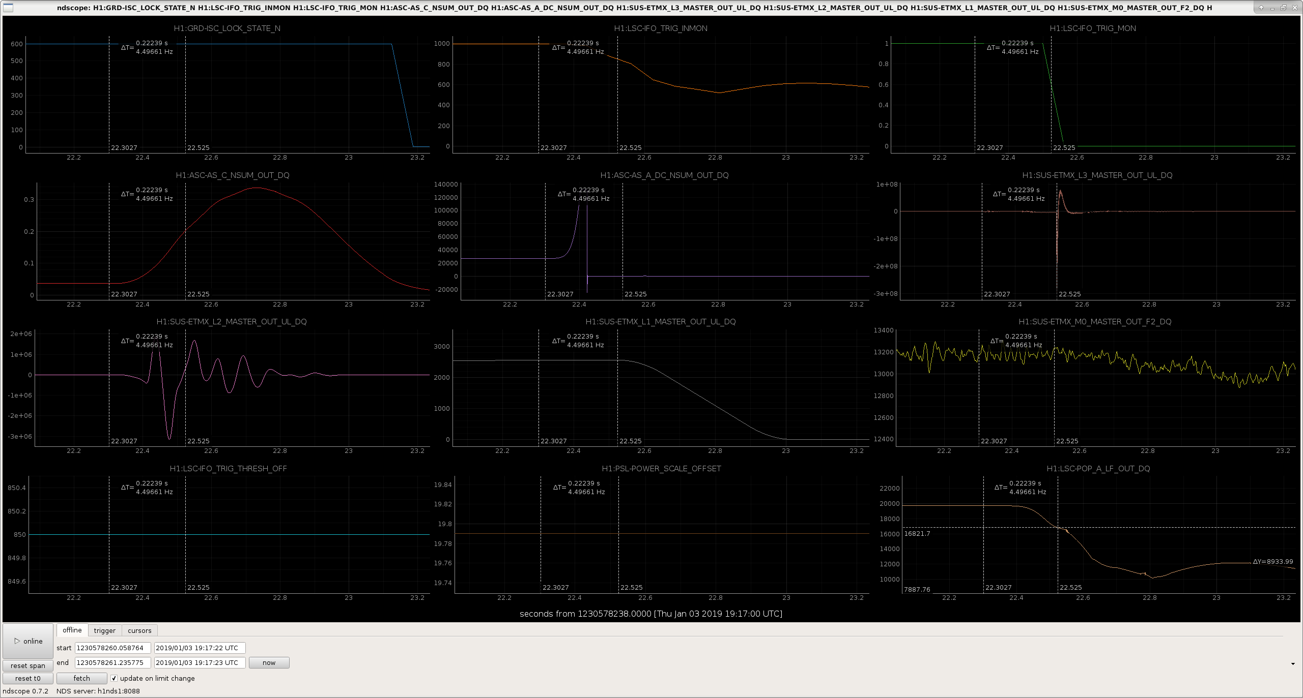
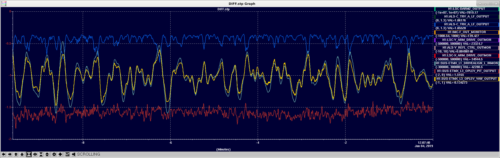
- The attached plot is the lockloss from the 16.5 hour lock. The first T-cursor on the left side of each plot is at the time that we *really* lost lock, as witnessed by a glitch in ASC-AS_C (when you zoom in a lot). The next T-cursor is at the time that the IFO trigger starts ramping signals down (when LSC-POP_A_LF_OUT_DQ falls below 850*19.78 = 16821). The top right trace in blue is the guardian state, so when it falls below 600 is when the guardian begins to turn things off. So, the IFO trigger is doing better than the guardian, but clearly needs to be turned off even sooner. We have a delay of about 0.22 seconds between true lockloss and when the trigger went, and a whole 1 second between the lockloss and the guardian recognizing it.
- The trick, of course, is to not make the trigger threshold so tight that if there is a slight fluctuation we kill the lock ourselves. In the case of the 16.5 hour lock, POP_A_LF_OUT_DQ fluctuates down to a value of 19230 at some point. If the trigger threshold were set to be just barely below this value (972 in the normalized units, since the PSL was injecting 19.78W at that time), we would have triggered off at 0.14 seconds after the true lockloss. So, maybe it is difficult to catch a lock much faster than that.
Guardian changes summarized:
- Commented out ISS_ON request in DRMI_CHECK_ASC.
- PRC1 input limiter is disabled in PREP_PRC_ALIGN in the ALOGN_IFO guardian.
- Reverting LOCKING_ALS state to lock both COMM and DIFF at the same time.
- Made lockloss trigger thresholds more strict, to catch locklosses earlier.
Other changes:
- Yarm green PDH gain down, second boost engaged.
Images attached to this report