daniel.brown@LIGO.ORG - posted 13:31, Wednesday 26 December 2018 - last comment - 09:19, Thursday 27 December 2018(46166)
Recovery after the dolphin crash
Hang, Dan Brown
Only EY was down from this dolphin crash so this recovery was quicker than some of the others.
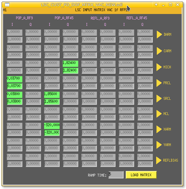
Initial alignment went fine except for PRC align. It seems the PRC1 filter changes made the other day (46151) made it unstable for initial alignment, probably too much gain. In PREP_PRC_ALIGN Guardian we switched off all the filters apart from FM1 (-20dB), it converged slowly and with FM1 off it still works.
Only one ALS lockloss during LOCKING_ALS, DRMI locked in about 20s.
Took about 2 hours until we were up again - although most of that was checking CO2Y table for leaks and figuring out what was up with PRX initial alignment rather than the Dolphin crash itself.


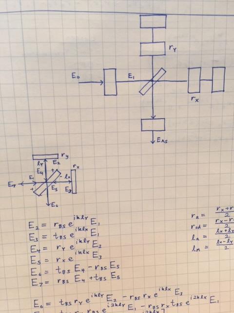
 The electric fields associated with this equation are shown in the fourth attachment.
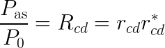
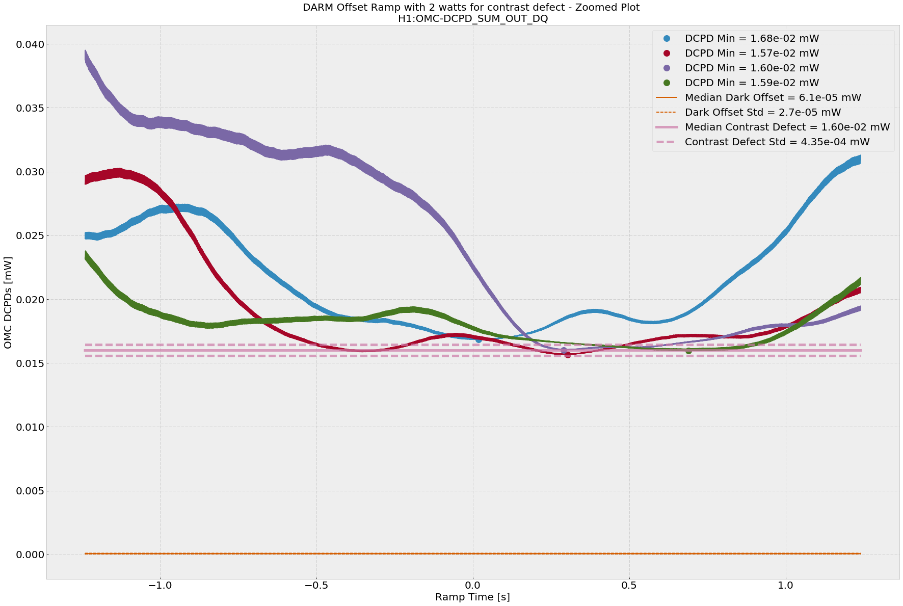
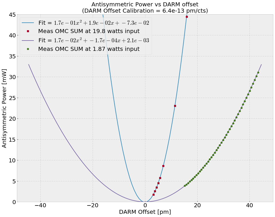
When DARM is locked on RF at 2 watts and the OMC is locked, we get about 11.8 mA, or 14.0 mW of power on the OMC DCDPs. This means the DARM offset is around 29 pm according to
The electric fields associated with this equation are shown in the fourth attachment.
When DARM is locked on RF at 2 watts and the OMC is locked, we get about 11.8 mA, or 14.0 mW of power on the OMC DCDPs. This means the DARM offset is around 29 pm according to 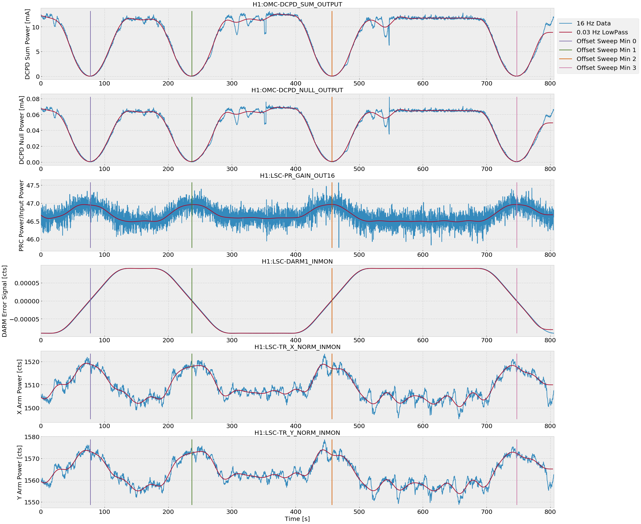
I've created FRS12051 to cover this crash. The ticket has been closed with an estimated 1.0 hours lost commissioning time.