Nutsinee, Sheila
Summary: We went back through the data from last night's squeezing injection. We see that the noise added to DARM doesn't depend directly on the CLF power, but it is suppressed by the LO locking loop (which is feeding back to the OPO length). This suggests that OPO length noise is coupling to DARM but not through the CLF or seeding; back scatter is one possibility.
Details:
Our goal last night was to change the CLF power to see how it impacts the noise added to DARM by the squeezer. We did not change the demod phase at all to try to adjust the squeezing angle. Since the locks were short last night, we were only able to get one or two injections in each lock, and our alignment was changing from lock to lock. We looked back at the data to find the CLF fiber launch power, which we use to estimate how much CLF was injected into the interferometer, the RF3 demod power, and a few other things. Since squeezing injections were done over a couple of locks, and the squeezer alignment was adjusted after the first lock, the alignment of the squeezer to the OMC was different for different times. The number in parenthesis in the legends of the attached plots are an estimate how well aligned the squeezer was. We took the ratio ((10^(RF3/10)/sqrt(CLF launch power)))^2, and normalized by the best alignment from last night to make this estimate.
The first observation (second attachment) is that when the squeezer is badly misaligned, we add less noise to DARM (which is what you would expect). The second attachment shows that we have more noise introduced into DARM with better alignment, the same injected CLF power, and the same analog gain in the LO loop. This means that we had lower optical gain in the LO loop, but also that we have less light from the squeezer reaching the DCPDs.
The next more interesting observation from is that increasing the analog gain for the LO locking loop reduced the noise added to DARM for a similar CLF power and alignment efficiency (first attachment).

One explanation could be that increasing the LO loop gain (which is currently feeding back to the OPO PZT) decreased the OPO length noise. Nutsinee and Daniel today found that we were causing a lot of OPO length noise (46058), which is not suppressed by our OPO locking loop since it feeds back to the laser. Since the OPO length noise was the dominant noise in the LO error signal at the time of these injections, the OPO length noise could be decreased by increasing the LO gain.
The OPO length noise could directly couple to DARM through intensity noise on the CLF. Since the CLF is off resonance in the OPO, the OPO length fluctuations cause intensity noise on the CLF, which is attenuated by the OMC but could still add noise if large enough. We also have the comparison in the third attachment (below), where the analog gain stayed the same, the CLF was increased and the alignment was improved, but the noise in DARM improved. The DCPD 3MHz demod shows that there is 3dB more 3MHz signal at the time of the yellow trace (3:46:59 Dec 18th), which means the LO loop gain was increased by sqrt(2), so the OPO length noise and the CLF RIN could have been decreased by a factor of sqrt(2). The CLF power reaching the DCPDs was a factor of 4 higher, so if the CLF RIN was the coupling mechanism we would expect the noise to be larger by 4/sqrt(2) ~3 in the yellow trace, but the noise is actually lower, suggesting that the coupling isn't through the CLF RIN. We are planning to revisit 45858, since that projection of CLF RIN to DCPDs was based on a RIN measurement made on ISCT6, before the OPO length noise would have been imposed on the CLF intensity. '
This comparison also suggests that the noise isn't due to seeding that comes through the AOMs in the CLF path, since there would be more seeding when we inject more CLF into the OPO, and when it is better aligned.

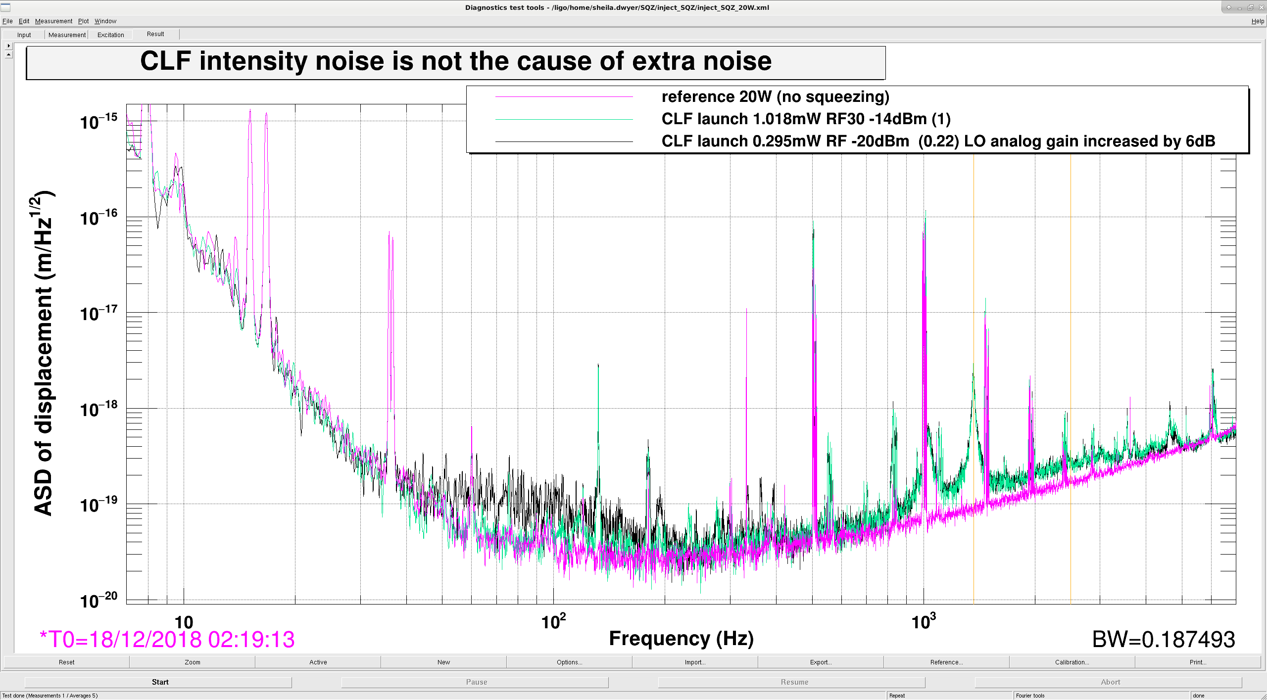
The fourth attachment is perhaps a more convincing comparison to see that CLF intensity noise and seeding aren't the cause of noise in DARM. At the time of the mint colored reference (4:33:40 UTC) there was 6dBm more 3MHz signal than at the time of the black reference (4:30:26 UTC), but the LO loop gain would have been kept the same since Nutsinne increased the analog gain by 6dB for the lower CLF power. (The shelf at around 100 Hz is a transient, we were having these kinds of transients which could be fringe wrapping during all of our locks last night).
Here are the times that we used. Some of these were very short measurements.
| Dec 18 2018 UTC |
CLF fiber launch power (mW) |
DCPD 3MHz power dBm |
| 2:19:13 |
reference no squeezing |
|
| 2:35:21 |
0.7 mW |
-24 |
| 3:46:59 |
0.7 |
-16 |
| 3:50:35 |
0.38 |
-19 |
| 4:33:40 |
1.018 |
-14 |
| 4:30:26 |
0.295 |
-20 |


T.J., Dave:
The CDS_CA_COPY guardian node did not fail in the way we hoped when the LSRPWR_MTR channels were removed from h1tcscs, resulting the camera-copy part no longer running. We may need to split the node out into two.