jenne.driggers@LIGO.ORG - posted 17:50, Thursday 13 December 2018 (45921)
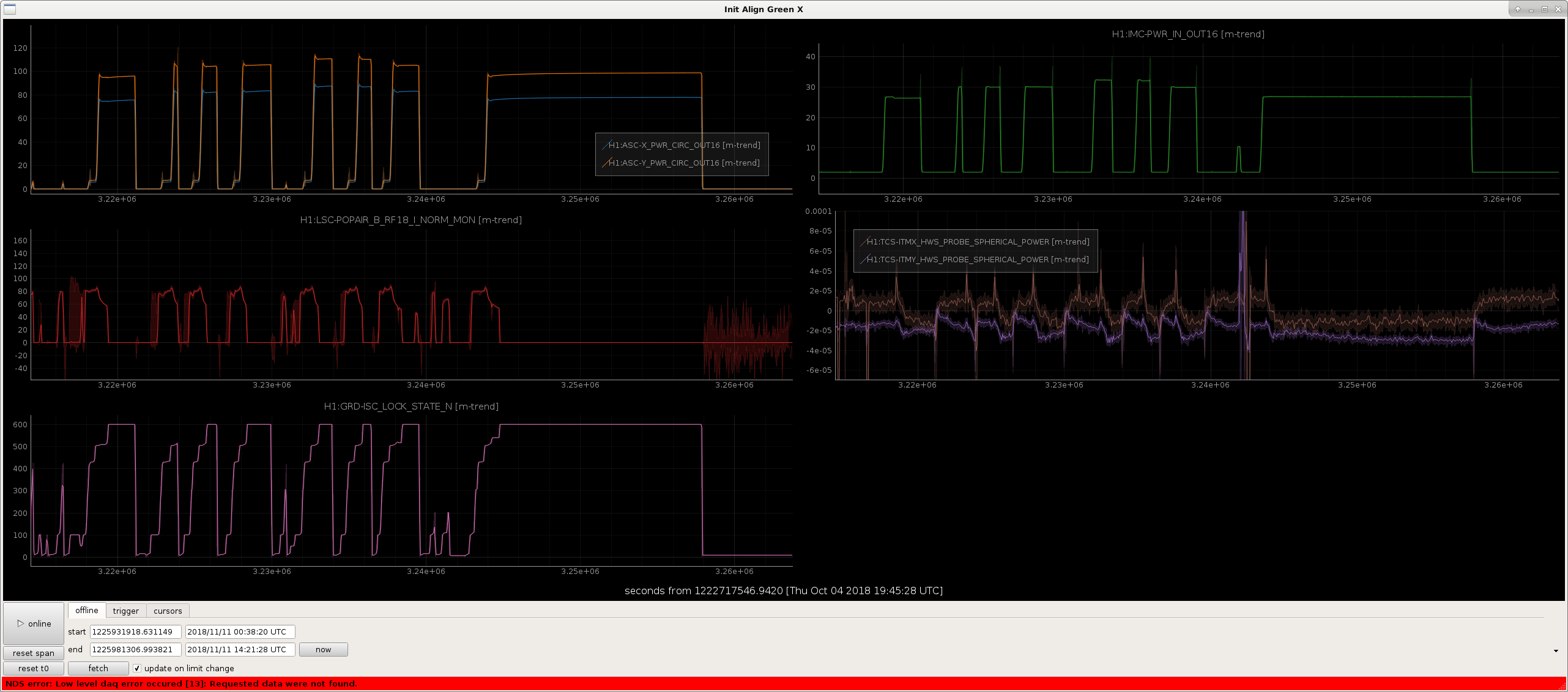
Green initial alignment set for Xarm, not for Yarm
[JeffK, Jenne]
With the current alignment of the IFO (same QPD setpoints for POP_A and SOFT), we reset the green initial alignment setpoints for the Xarm green WFS and camera spot.
We tried to move the Yarm input pointing QPD setpoints by hand to get the Yarm green to lock while we are locked, but couldn't get the Yarm to lock on a 00 mode without falling off the PD. So, for now, rather than pico-ing, we have left the Yarm initial alignment setpoints alone (reverted to how they were earlier today).
We're considering moving our POP and / or SOFT setpoints to get POP18 back up and more smooth, so we'll just live for now with having to engage the full ifo asc slowly.