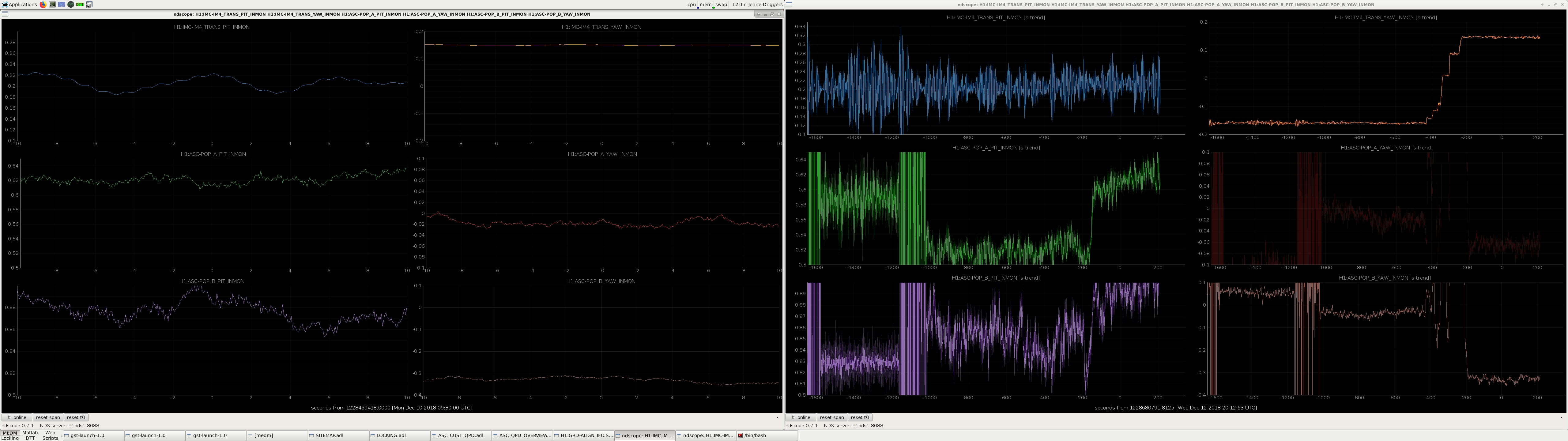
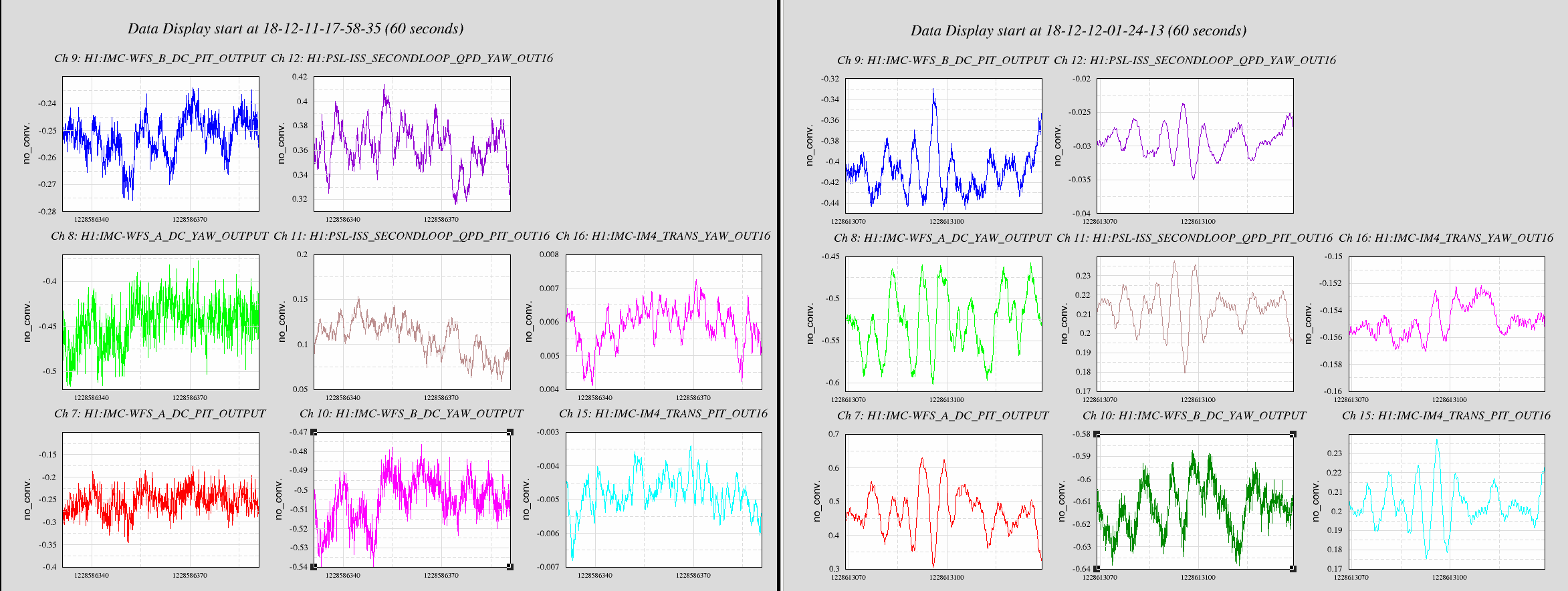
I trended a time from Monday when the IMC was locked, and we had the PRM misaligned (I actually used a time when we were doing initial alignment, and were still on Xarms green). I then moved IM3 to get the IM4_Trans QPD spot back to that time, and moved IM4 to get the POP QPD spots roughly back to where they were. While I did touch pitch a very small amount, this move was almost entirely in yaw, which is consistent with the PSL beam shift in yaw from Tuesday maintenance.
Niko and Ed are currently redoing an initial alignment starting with Xarm IR (green arms won't be affected by the IM move).
In the attachment, the plots on the left are from Monday, and the plots on the right are from today during / after my move. The Yaxis for each trace is the same for both the Monday plot and the today plot, so you can see that IM4 Trans and POPB were both off in yaw, but now are much closer to where they were on Monday.
After some failed attempts to install a noise eater:
we have now installed a 532 nm 200 MHz AOM from MIT.
Beam profile after this AOM looks fine (attached) with ~45 mW input power. The green pump fiber had to be realigned and again has 83+/-2% coupling efficiency to the patch panel on ISCT6 (so this fiber is fine).
However the power to SQZT6 has dropped recently and is still low, but is clearly not due to any failure of the fibre between the Green input coupler on ISCT6 and the patch-panel on ISCT6. Nutsinee will add a post with more information on this.
The frequency synthesizer doesn't have enough power to get enough diffraction power, so I added a ZHL-1A Mini-Circuits amplifier. The settings on the ifr are 200MHz/0dBm for the carrier with an external AM modulation at 50% bias. Since the CM board for the OPO isn't used at the moment, we connected the first input the to DC monitor of the OPO REFL diode, the second input is connected to a DAC channel (OPO_EXC) with a 100Hz low pass. The later provides a DC bias to set the requested power level. The fast output is then connected to the modulation input of the frequency synthesizer with a 450Ohm series resistor (which forms a 1:10 divider together with the 50Ohm input). The bandwidth of the AM modulation input of the ifr is about 30kHz. However, we measured a significant phase lag which will limit the ugf to less than 20kHz.
T.J, Dave
Tuesday we integrated the old camera_copy into the new guardian CDS_CA_COPY node. Its MEDM was updated (attached).
The original camera_copy was a python script running on h1fescript0 within a screen environment, with guardian DIAG_MAIN checking that it was running.
Wiki documentation is being updated.
I've left a notification in DIAG_MAIN to look for any errors with the CDS_CA_COPY node. Though this may be seen as redundant, DIAG_MAIN is often much more visible and should grab a user's attention faster than a buried node with a message/error.
Sheila, Craig, Terra, Seb, Dan
Some notes from tonights locking attempts:
We looked at the RF mon of REFL_A_45 during a 20 W lock time. The RFPD's 45 MHz output is saturating frequently (previous discussion of REFL9):
Using a fast scope with 50 Ohm input, we looked at the RF mon output of the demod board. The RF is usually low, but can swing up to 80 mV-pp from seismicity. That's 1.2 Vpp at the input to the demod board. The signal is completeley due to the 45 MHz; there are no other significant frequency components.
Since the REFL45 is not used by any loop at the moment, it may be the case that its OK to let it saturate, but we don't know what effect it has, if any, on the 9 MHz output of the same circuit. To be investigated.
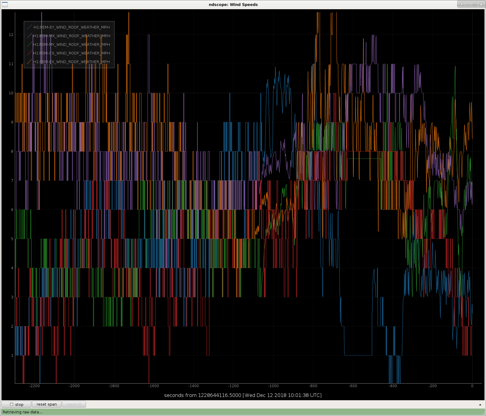
as a test to see how people like it, I changed the .SMOO param on the Wind Speed monitor channels. This does some moving averaging in the server so the traces are easier to read.
This will be reverted on the next reboot, but also can be done at command line by setting the SMOO field to zero. At the moment it is 0.9. See attached plot: left side is quantized and no smoothing.
The CS channel seems to ignore its SMOO, but probably there's a way to get it to SMOO too.
The CS channel comes from Beckhoff. The other channels will eventually migrate to Beckhoff as well. Smoothing for the channels in Beckhoff may have to be done in the PLC code.
Rana, Patrick,
Can you please include your best guess as to what sort of filtering is applied by the 0.9 SMOOer? In particular at the 30 mHz to 300 mHz range? One of the open questions for the wind fence is how much turbulence is added by going over the edge of the building, and so we try to compare the free-stream spectra with the building top spectra, so additional filtering in this band is good to understand.
Thanks
-Brian
Rana is likely using the existing SMOO field in the EPICS database to modify the conversion - see EPICS wiki, among other places. Smooth runs from 0 to 1, with 0 being not smoothing and 1 being 'infinite' smooth (i.e. no value changes). The formula in the documentation iseng units = (new eng units × (1 - smoothing)) + (old eng units × smoothing)To determine the frequency of smoothing, you'll have to check the sample rate that the measurement is made at (also in the EPICS database file).
Robert pointed out that putting in SMOO will make it hard to make historical comparisons, so I returned all the SMOO to zero tonight. We'd like to make new channels which have 0.95 SMOO, so that we can maintain the historical comparison and also have smoother channels. Anyone can help with new chan making?
We changed the refl air phases to the values measured here 45791 This change was made around 7:15 UTC December 12th. The first time we locked DRMI with these settings it took about 3 minutes after making the change. The second time was just over 10 minutes. While it doesn't seem obviously better or worse, I would like to try leaving these phases in for a day or so to look at the DRMI locking times.
PRMI would only stay locked for a few seconds after these new phase changes, seismic is pretty high at the moment though. DRMI still locked ok with this phasing.
Since Sunday, each day we are spending many hours waiting for DRMI to lock. As people are well aware of, the DRMI here seems to go through phases of good/bad locking. Good locking is where the acquisition time is mostly < 10 minutes. When its bad, it may be 30~60 minutes. As is usual, we sit around wondering if its "the alignment", "the wind", or the "the microseism".
In the LVEA, the common mode rejection of the slab is ~1000 at the microseism peak, so most of the 0.1-0.3 motion that we see in the DRMI comes from differential motion induced by the SEI and SUS.
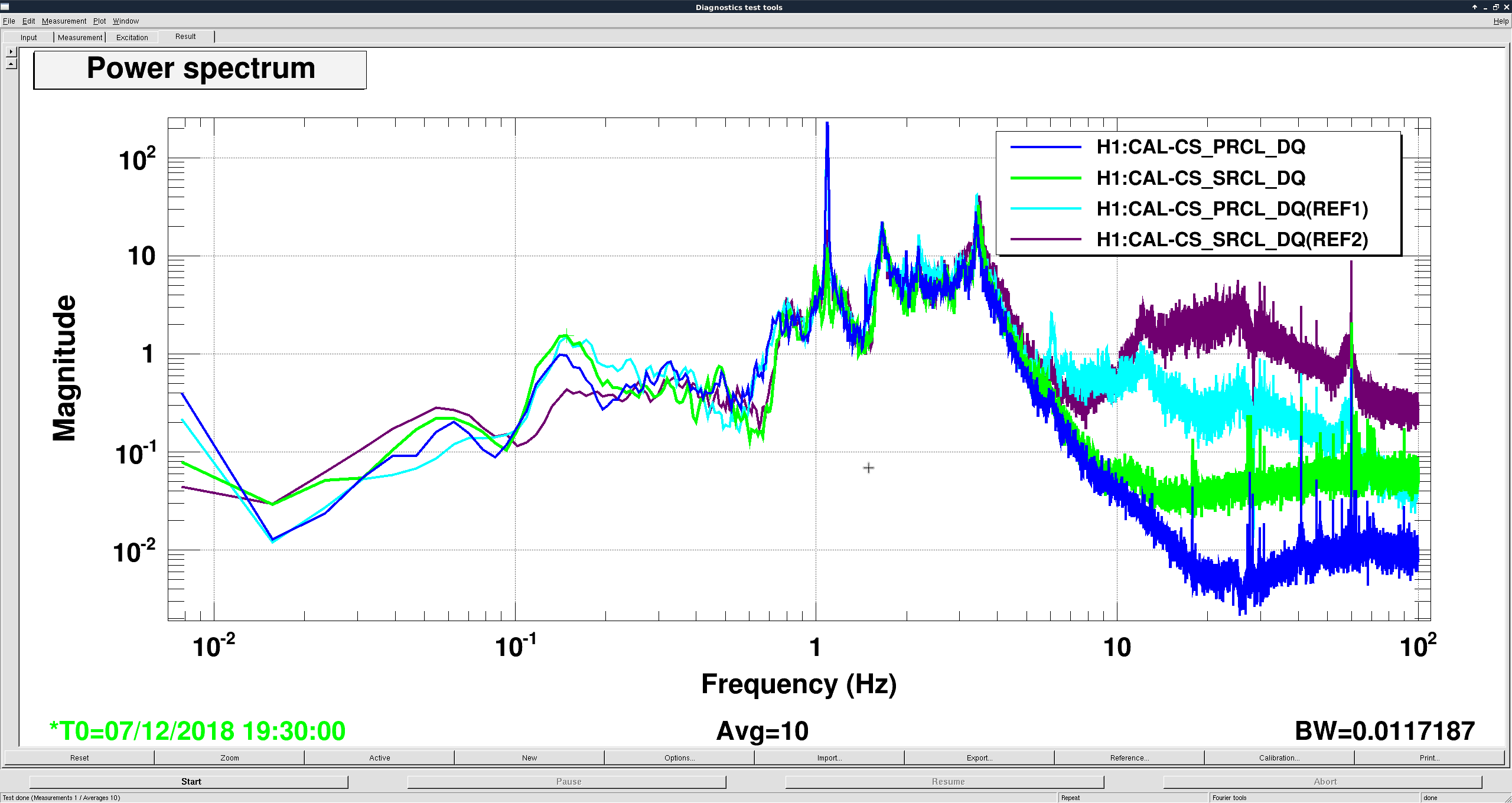
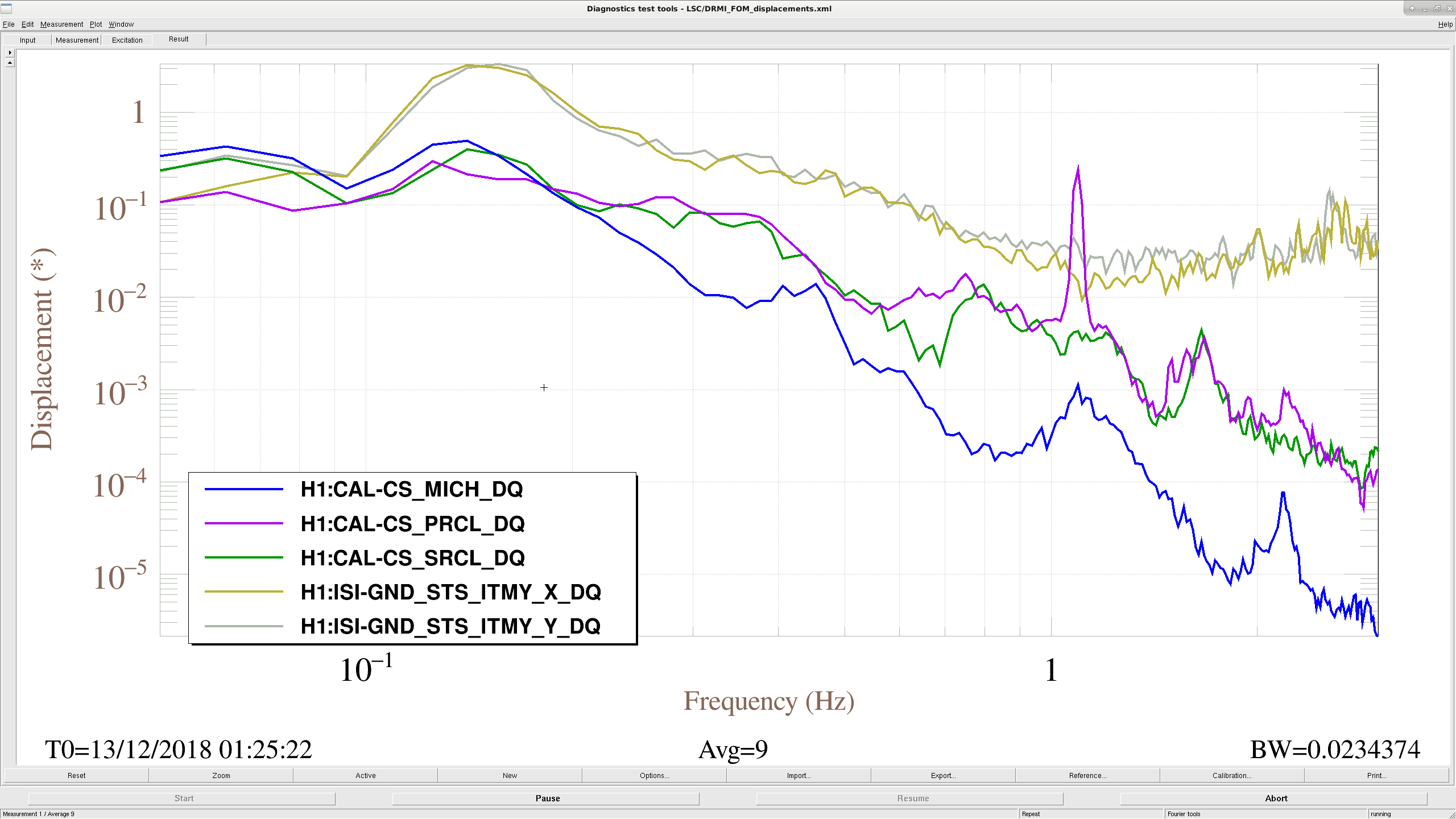
As an example, I'm attaching the LSC control signals from a DRMI lock earlier tonight, compared to the ground motion. It seems like we're getting around a factor of 10 suppression for MICH/SRCL, but only a factor of 4-5 in PRCL. But actually, its probably even worse. The CAL-CS channels don't take into account the M1 offload (what is the M1 crossover frequency for the length control on SRM and PRM?).
At LLO, Arnaud is looking into some improvements to the ISI controls to make the PRC/SRC HAMs follow the BSCs better. If the main microseismic impact to DRMI locking is the PRC velocity, we would win a lot just by getting a 2x reduction at the microseism.
Part of the reason the SRCL length is lower at the microseism might be the work I did a couple weeks ago on HAM4. PRCL sees similar coherence with ground Z motion at the microseism. Arnaud had talked about trying similar feedforward to HAM3, but it was unclear if improving PRCL would make MC-L worse. I haven't found any alogs documenting either way, so far. Looking at a couple locks over the last week, I would guess that MC-L is dominated by other stuff at low frequency, so maybe it doesn't matter so much when the arms are locked.
If I could be allowed to try doing some ground Z to HAM3/PRCL sensor correction, I would need about an hour or so to get and tune the ISI drive to PRCL transfer function. I can likely do any on/off tests without bothering anyone.
Attaching a couple plots comparing SRCL and PRCL, before and after my work on HAM4.
First plot are just spectra, blue & green are before, light blue & purple are after. PRCL seems unchanged, but SRCL has ~3x less motion at the microseism after turning on the extra HAM4 sensor correction. It is worth noting that the PRCL microseismic motion is higher, for the case with the HAM4 sensor correction on, so the improvement to SRCL is probably better than shown here.
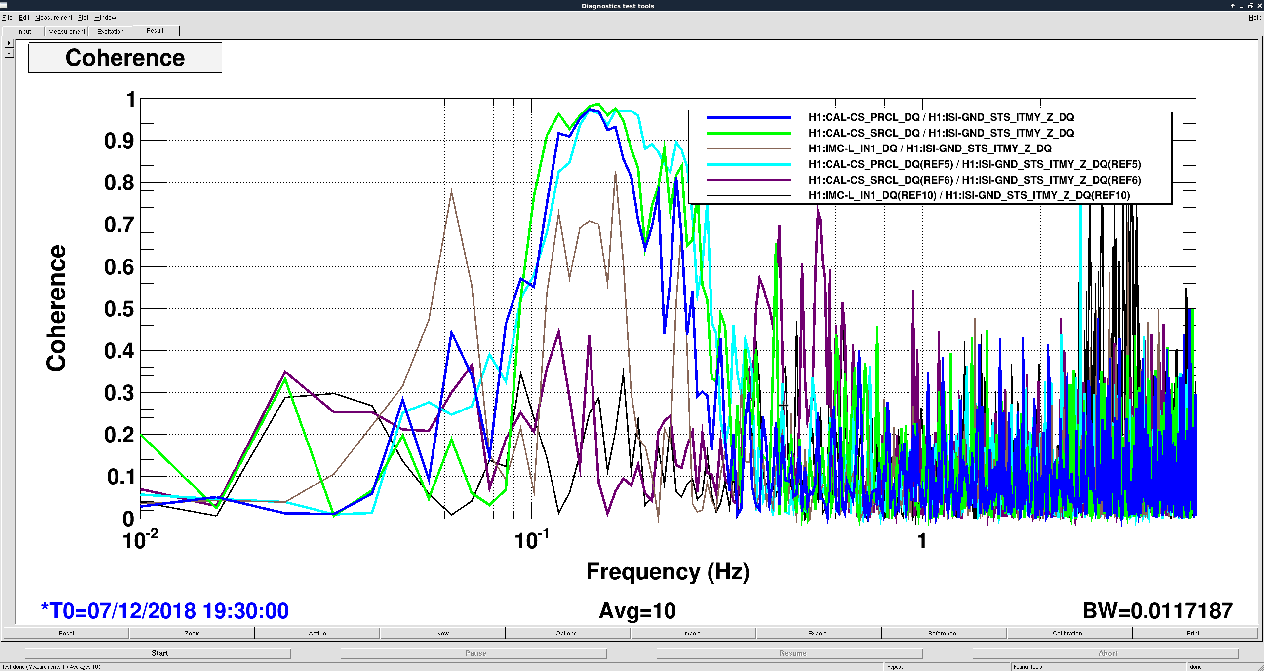
Second plot shows the coherences from the ITMY STS Z to PRCL,SRCL and MC-L. MC-L changes, I don't understand why. PRCL, is more or less unchanged, but SRCL goes from about .95 coherence before, to basically nothing at the microseism. I think it is worth trying this for PRCL.
This is how DRMI looks now with the added HAM3 GND Z to X sensor correction. PRCL is now down to the same level motion as SRCL.
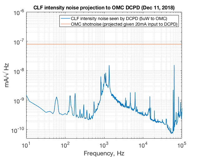
It wasn't CLF intensity noise.

While we are having some wind I unlocked and misaligned the mode cleaner and measured the OMC DCPD dark noise with different whitening filters on. The configuration we have been using is one stage of whitening. It looks like we don't have much to win in terms of dark noise by turning on the additional stages.
J. Kissel
We lost lock this evening (we think) due to a hefty gust of wind at EY. I didn't notice, because the wall FOM on Video 1, which was recently "upgraded" to a DMT viewer showing a several panel ground motion vs. wind vs. tilt correction performance display doesn't update -- and I thought it does. (And I didn't believe that the EY 30 mHz - 100 mHz Y band on the front-wall, nuc5 display could elevate "so high without any signs of wind.")
Because this has been a perennial problem with DMT viewer, and the display turned out to be barely legible on the smaller screen, I've reverted the display to using the StripTool template we used during O2.
The template I used I found to live in
/Users/controls/Desktop/WIND.stp
only on the video1 machine, which was a bit tough to find given the template does not point to any userapps version controlled strip tool, and traceback through the OPS wiki's version of the https://cdswiki.ligo-wa.caltech.edu/wiki/Operations/FiguresOfMerit only revealed the right location in *one* version (and it had the wrong name). But I found it!
Please, in parallel let us
- revert the video1 FOM start up scripts to using this template (and opening up the stick notes to show legible axes labels)
- Add a "until DMT viewer works reliably, use this" section for the start up instructions of the ops wiki for video1
- try to get DMT reliably running, especially through maintenance days which involve restarting of DMT / GDS code.
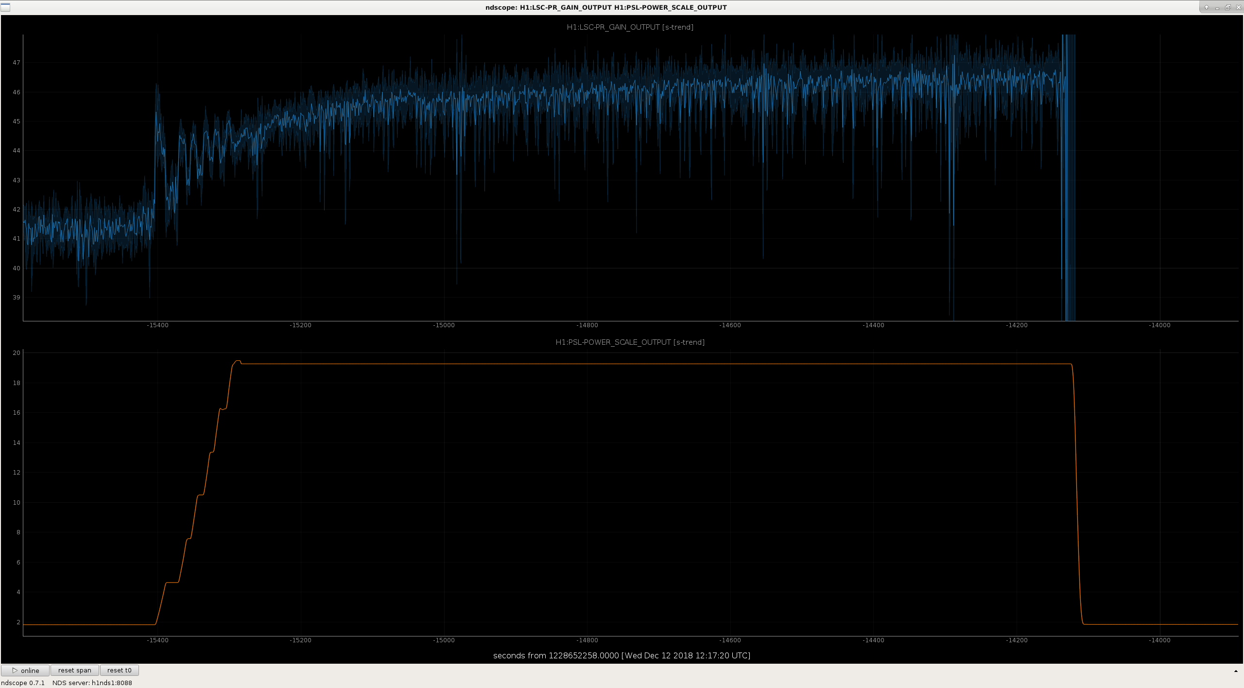
J. Driggers, S. Dwyer, C. Gray, J. Kissel, T. Shaffer, P. Thomas, C. Vorvick, J. Warner, H. Yu Corey and I (starting about 13:00 PST), then Patrick, Sheila, and I (after 16:00 PST), plus a supporting cast listed above, recovered the interferometer after maintenance today. I detail all the catch points below and their cause / gotcha / solution if it was identified. The message: nothing broken, just the usual challenges of recovery from a heavy/scattered maintenance day. - PSL Periscope PZT swap: After PSL team installed a new PZT at the top of the PSL periscope (LHO aLOG 45853), they ran out of time, and left the beam going into the vacuum system a little bit off in yaw translation. - Cheryl, Sheila, and I confirmed on several metrics (IM4 TRANS QPDs, MC WFS DC "QPDs", ISS INPUT QPDs) with the IMC locked that the alignment in and out of the mode cleaner had changed. Solution: after driving the PZTs and MC1 to recover the spot position on the REFL MC WFS "QPDs," we locked up the IMC. The "gotcha": for beginnings of the locked IMC time, with all IMC ASC running, somehow the input to the PZT YAW loop had been turned off. This drove the IMC alignment, and downstream alignment metrics into very different / wrong places. Once we found the gotcha, the IMC ASC system restored the IM4 trans P & Y alignment to 0.2 to 0.1 "QPD units" (proportional to beam radii), respectively, where they had been 0.0 and 0.0. Further, the ratio between MC2 TRANS SUM and IM4 TRANS SUM was within 1% of that before the PZT swap, so we elected to move on. - Initial Alignment of Arms on Green: Corey and I are still new at this, so we struggled to figure out the three-mirror alignment system against several expert methods and metrics. Just stupid user error (i.e. by me) slowed us down on getting the Y arm aligned, but this needed extra work because of the ETMY ISI in the Y arm had been taken up and down as necessary for a model restart like today (LHO aLOG 45844). - What we learned: remember that if all is working perfectly and the arm(s) is (are) already well aligned, then there are 1 LSC + 3 Cavity Axis DOFs * (P and Y) = 7 control loops that help make this first step easy. "Easy" means -- just click "INITIAL ALIGNMENT" on the arm guardian state, and all the work is done for you. HOWEVER, if optics are not well aligned, then there are several layers of debugging configurations that you can try to get you back to perfect functionality: - Level 1 bad: if - the green arm transmission is between ~0.75 and 0.8, - the 7 (likely the ASC) loops running in INITIAL_ALIGNMENT are only making the arm power worse, but - the green camera spot image shows mostly 00 modes, and - the error signal for one or more of the green ASC loops are very large (say if the green ITM camera gets jostled like last week; LHO aLOG 45699), then You can request the normal INITIAL_ALIGNMENT state, but intentionally and manually disable the problematic loop, and slowly adjust the alignment of the uncontrolled optic / DOF in order to reduce the error signal and increase the green arm transmission above 0.8. Then request UNLOCKED and return to INITIAL_ALIGNMENT as normal (removing whatever you've done to temporarily disable the problematic loop). - Level 2 bad: if - the green arm transmission is between ~0.75 and 0.8, - the 7 (likely the ASC) loops running in INITIAL_ALIGNMENT are only making the arm power worse, - the error signals for the green ASC loops are large, and - the green camera image shows some flashes on non-00 modes, then You can run the LOCKED_NO_SLOW_NO_WFS state (you have to open the "ALL" button on the mini-guardian screen to see this state). In this state, *only* the LSC loop is used to lock the arms, but you're not fighting bad ASC loops. Here, adjust all three optics until you get the green arm transmission up above 0.8. Then revert to Level 1 bad instructions (or if you're lucky, you can go back to the "easy" instructions). - Level 3 bad: if - the green transmission is below ~0.75 (say, at the 0.6 level or lower), - you're seeing very few 00 modes on the green camera spot - requesting LOCKED_NO_SLOW_NO_WFS doesn't work (i.e. the guardian goes into "dance party" mode, quickly switching between many states) You should just leave the arm in the UNLOCKED state, and try - using the alignment slides to restore the ITM, ETM, and TMS to its top-mass OSEM values (not just the slider values) at a known good time of green arms locked, - focusing on aligning the optics / chambers that you know were disturbed today, and/or - keep an eye on the *red* transmitted power (if you get decent RED flashes, then the ITM and ETM are probably well-aligned, and your TMS is bad. If you have no red flashes, focus on the arms first) until you get the green arm transmission flashes about 0.8. Then revert to Level 2 bad instructions (or if you're lucky, you can go back to level 1, or even "easy"). Corey took the X arm, and I took the Y Arm. Corey was able to get by with "easy," I have to go to Level 3 Bad (some of which was my fault by accidentally looking at the RED transmitted power instead of the GREEN on my ndscope). - Initial Alignment of MICH / the BS: The "gotcha": over the past few weeks, the functionality of the MICH_DARK alignment states have been broken. Folks are working actively on it, but it's not yet fixed. The solution: one needs to simply request MICH_DARK_LOCKED, reduce darken the MICH spot on the AS port camera as much as possible by moving the beam splitter, and *skip to the next alignment step* SRC_ALIGN. - Running the DOWN state vs. the ETMX ESD: Once initial alignment is complete, one goes back to the main ISC_LOCK guardian and requests DOWN / PREP_FOR_LOCKING, and there it may get stuck constantly repeating the same commands on a loop over and over. The "gotcha": the charge measurement scripts (which create data that informs, e.g. those run today LHO aLOG 45843 that helped check the functionality of the ESDs after the power-supply configuration swap LHO aLOG 45845) do not gracefully handle exiting prematurely, and often leave the ETMX ESD in a mid-measurement configuration. This is a regular sticking point, and folks are working on making these scripts better, but it's not yet fixed. The solution: Thus, in order for the ISC_LOCK guardian to complete the execution of the DOWN state, you need to check that the following things are OK: - There is some requested drive signal coming out of the ESD system - Make sure that the bias voltage is set to "the right value" (currently -9.3; check SDF) - The binary IO configuration of every quadrant is in the "HI VOLTS" and "ENGAGED" state - Make sure the ESD driver is ON by looking that there are non-zero(or non-small) HV MON values in the very bottom right corner of the ETMX SUS overview. Once these are good, then the ISC_LOCK guardian should be able to proceed. - Locking PRMI / DRMI when it's been very slow/flaky for weeks, and you otherwise don't know if something from maintenance day is preventing it from working, or it's just the normal very slow/ flaky PRMI/DRMI: Here's where you go into the standard maintenance day tail spin of many different possibilities that launch many parallel investigations from various maybe-related clues, and then you end up changing nothing, and the problem fixes itself. After ~30 minutes of "the usual" attempts at increasing POP18/POP90 flashes by tweaking PRM / BS / SRM alignment, we were unsuccessful. The thread of clues from several folks investigating: - Sheila notices that the Tidal error signal is large, which we "know" is informed by IMC_F, which -- in the middle-of-the-lock-acquistion state of locking PRMI / DRMI with arms controlled by ALS, but off resonance -- is informed by ALS_COMM, which is probing the arms. - Sheila starts looking at optical lever motion, and notices that ETMX optical lever is moving "a lot," at ~1 urad pk2pk. - The excess motion is intermittent, on the ~5 minute time scale. "It's fixed! Who changed something? No one... Oh, it's back again..." - That launches Jim and I on a "which ISI is poorly performing?" investigation, because we know that sensor correction has been under construction for a week or two (e.g. LHO aLOGs 45641 45815), and folks were at the end stations today that may have rung up the BRSs into non-functionality. - The BRSs turn out to be fine, but it takes some effort to tell because of the sensor correction construction zone. - I find (via the SUSPOINT channels for the globally controlled cavity optics) that ITMY (not ETMX) is moving a factor of 2 to 4 more in the 30mHz to 100mHz (EQ) band. - In parallel, folks are rifling through a very red SDF system looking for settings clues. Lots of differences (from normal, fast-paced commissioning), questions asked about Beckhoff restarts not restoring settings, and too-little-expertise makes this a challenge to come up with any substantial clues. - Questions about last night's settings changes from commissioning the DRMI distract us for a bit - In parallel, Sheila and Patrick request the ISC_LOCK guardian to DOWN and use unorthodox guardian configurations and manually taking various suspensions to ALIGNED, they lock PRMI and DRMI alone, without arms. It locks up well, so they adjust the PRM / BS / SRM alignment in lock, but the adjustments are tiny. - Just as I'm trying to show when the ITMY ISI performance started to degrade, Sheila and Patrick restart the ISC_LOCK acquisition sequence, and DRMI locks right up with out them changing anything. Thus, we made it to ENGAGE_SOFT_LOOPS -- i.e. IFO is fully resonant and all ASC loops are in engaged -- no problem. We declared recovery complete at that point, but lost lock shortly after, and we've not been able to recover...
The mount for the PZT in the IO path on the PSL, IO_MB_M4, was swapped from the 2" mirror and the damped mount to the new PZT mount.
Aligning with the new PZT mount is challenged by having to remove the entire mount from the table, to access the bolts underneath, to adjust the +/-X position. There was also a change of the beam alignment when securing the bottm plate to the table. The beam was carefully aligned to IO GigE camera 2 and camera 3, and when the bottom plate of the new mount was secured to the table, the beam was gone from both cameras, and an offset was introduced into the IMC_IN beam. With the PZT it was possible to restore a beam to IO GigE 2, the camera that is on the bottom periscope transmitted beam. It was not possible to restore both camera images with the PZT. This indicates that the change in IMC_IN position and angle are due to the PZT swap. It was past noon, so the decision was to leave this change as is, lock the IMC, and evaluate how it and the beam downstream was affected, instead of using M3 and the PZT on the PSL, to restore an image to both cameras. The change in IMC_IN on the iris at the bottom periscope was identifiable as yaw with an IR viewer.
The reference beam from the shutter (between the PSL and HAM1) was recorded before and after the PZT swap. Those pictures show the difference is between the before and after beams is 1mm and 2mm in pitch and yaw (image attached).
Sheila and JeffK moved IMC DOF, Corey and JeffK started an initial alignment, and now the effort is to lock.
BEFORE reference time 12/11 18:00 UTC, AFTER reference time 12/12 1:24 UTC. A snapshot showing IMC WFS, IM4 Trans, and ISS Second Loop QPD signals is attached.
- Cheryl, Jason, Keita
Two drawings. The first shows the layout of the IO GigE cameras 2 and 3, both on the bottom periscope transmitted beam (IMC_IN). The second shows the change (exaggerated for clarity) of the front face of the PZT mirror (placed on the table vs secured).
This mount swap is in reference to IIET Ticket 5132.
The new mount is documented by the below details:
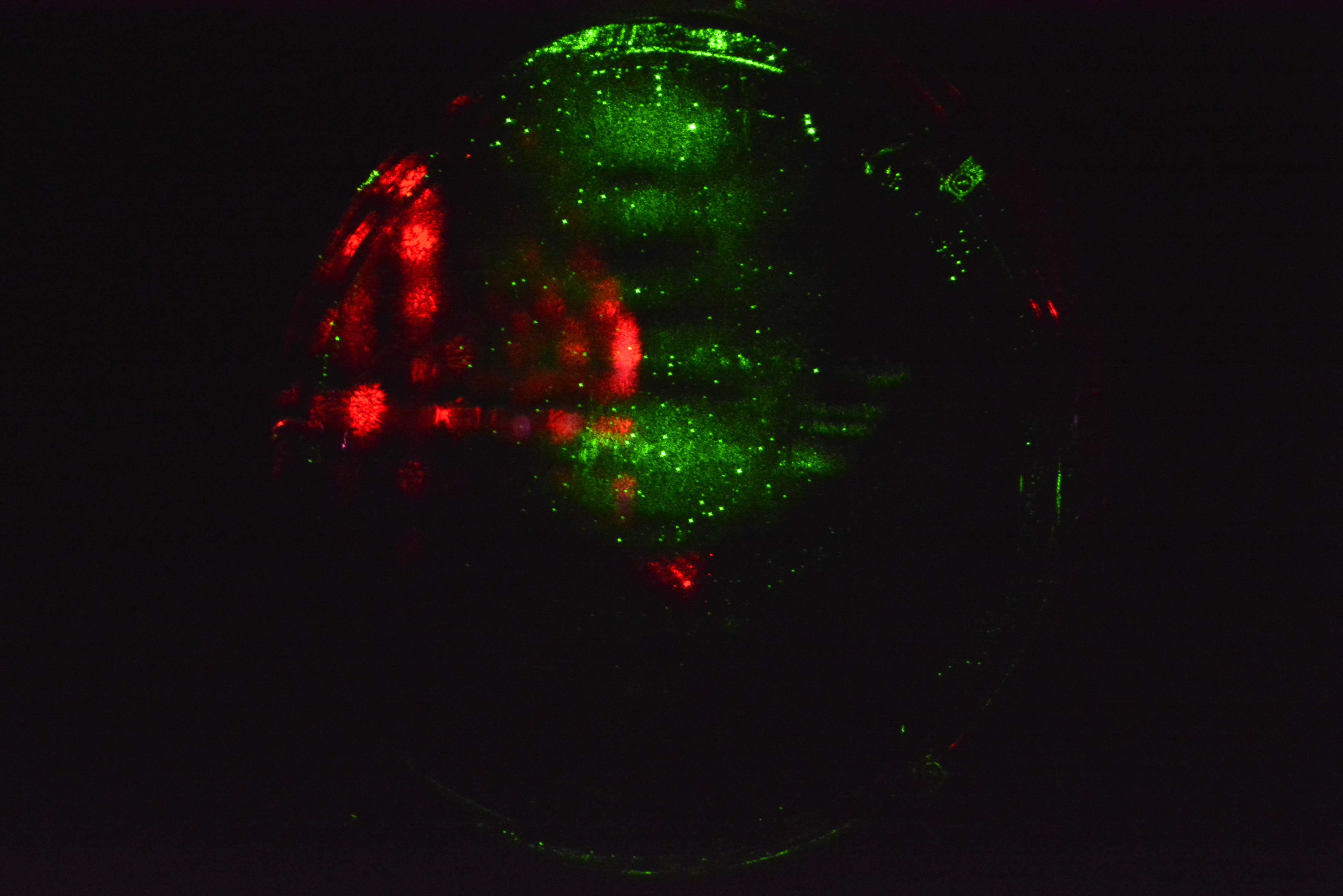
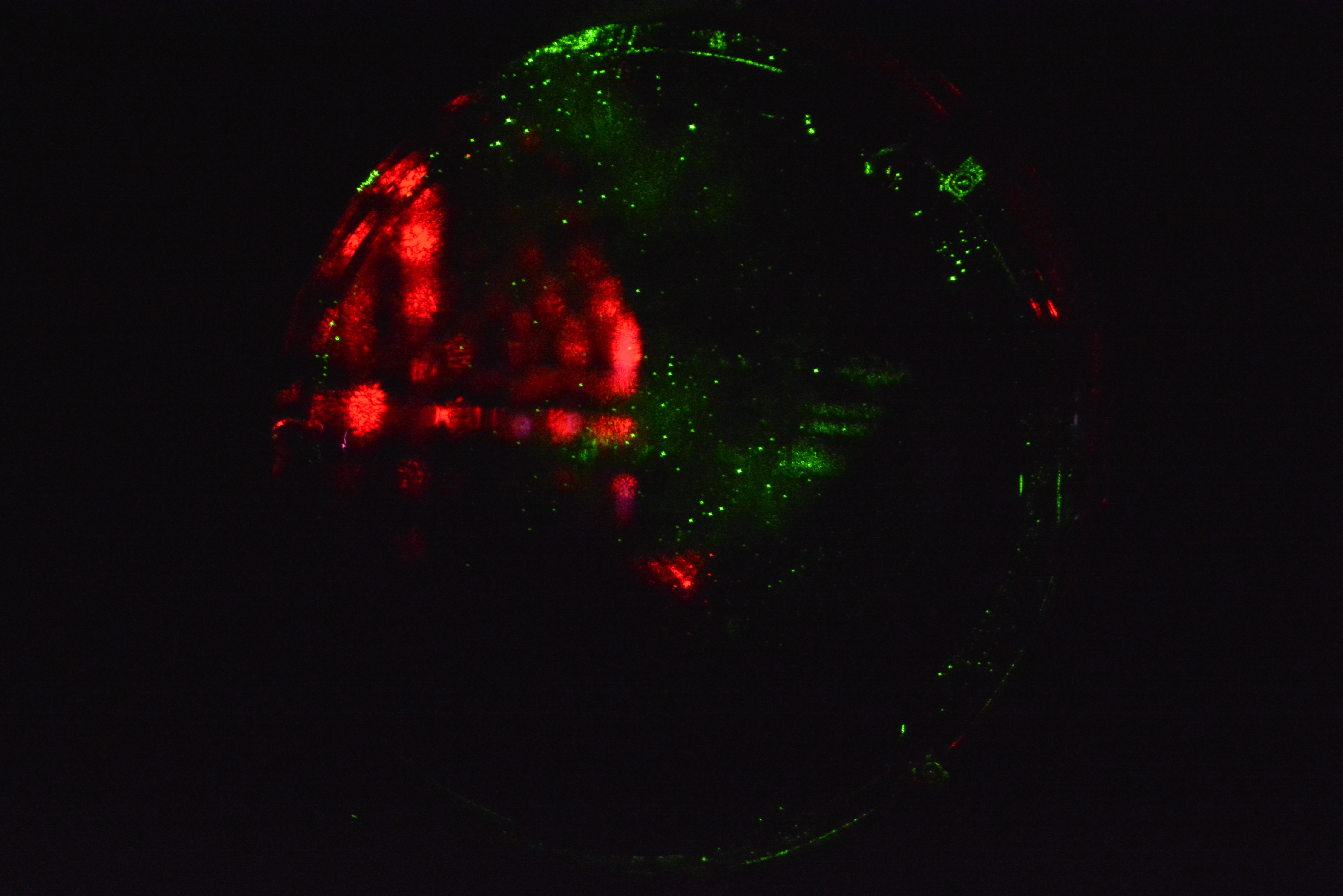
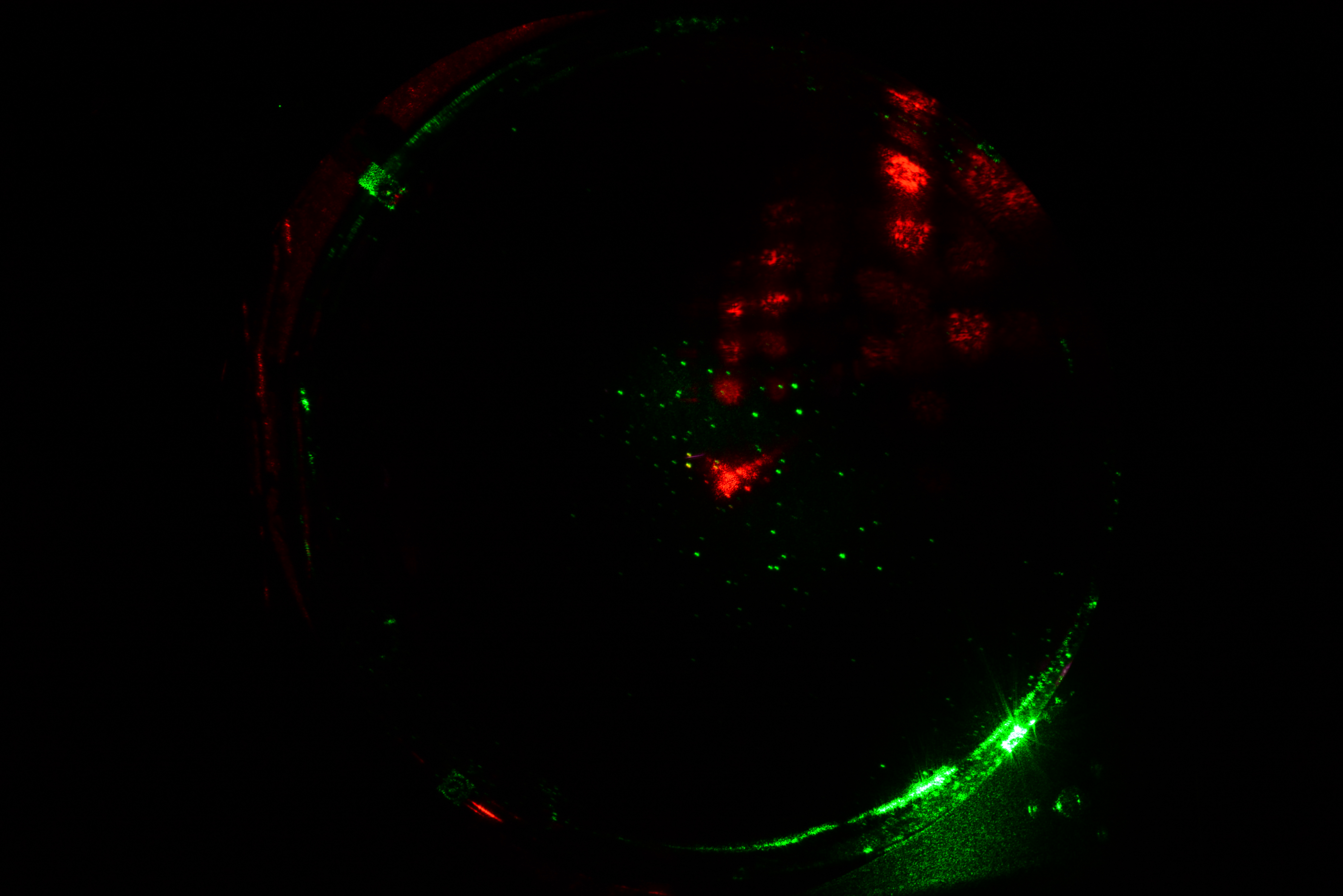
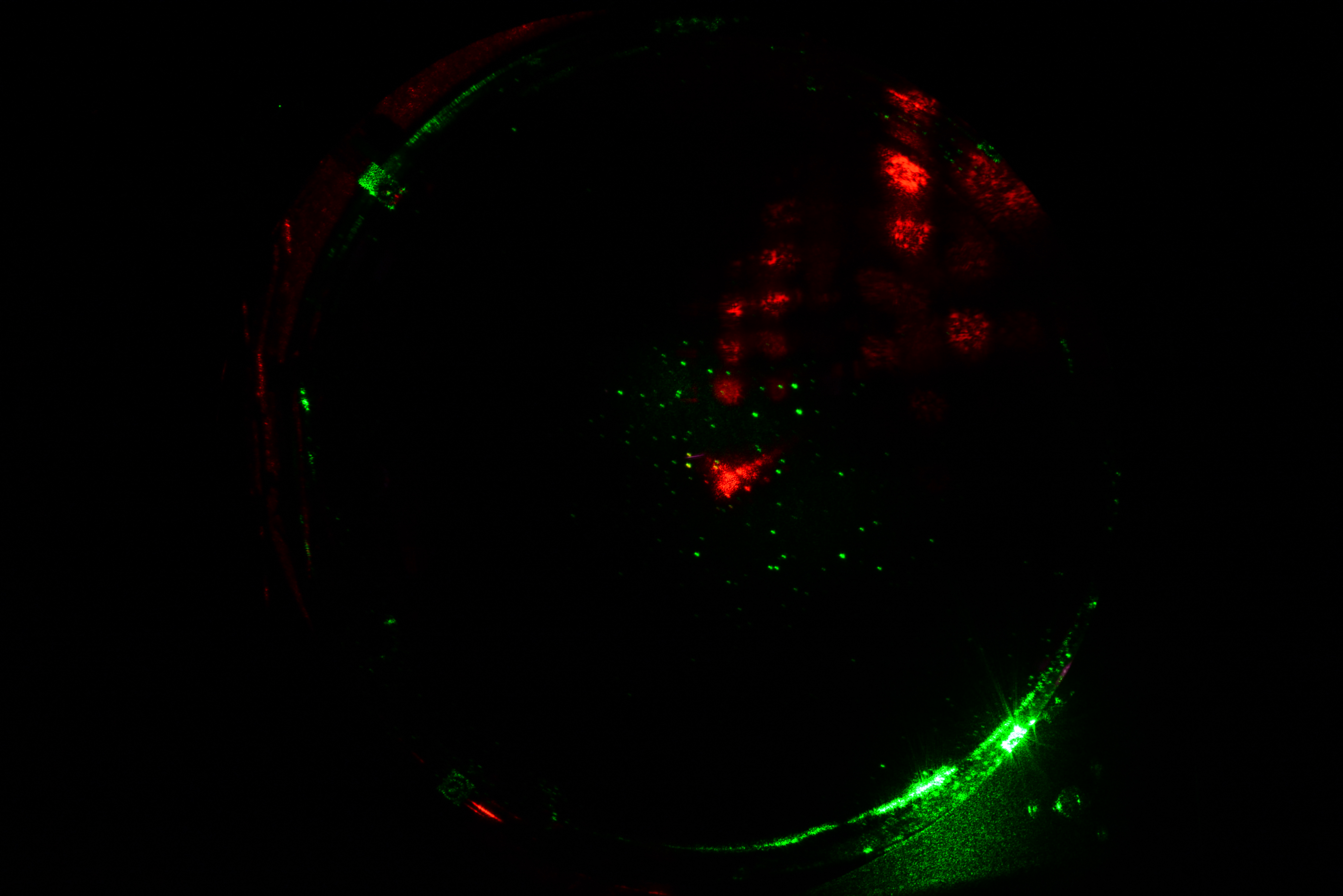
Took pictures of face of ITM-X and ITM-y under green light as the IFO unlocked while setting up. Will try to get a set of shots under IR at at least 20W before the holiday break.
There are two shots of each optic at different exposures and focus points.
| Optic | Frame # | Shutter | ISO | Focus |
|---|---|---|---|---|
| ITM-Y | 111 | 1.0 sec | 6400 | 1725 |
| 112 | 1.6 sec | 6400 | 1725 | |
| IYM-X | 110 | 3 sec | 800 | 1745 |
| 117 | 3 sec | 800 | 1625 |
to do precise image subtraction in the future (to detect small movement in the point scatterers) we would like the camera position to remain the same. It would be nice, therefore, to design a camera holding jig that would get us back to the same place w.r.t. the viewport. Would be easier to make that analysis quantitiative this way rather than do a lot of image scaling/aligning with camera at different positions.
Rana, Very good points. The camera/lens assemblies are bolted to the Viewport Camera Housing (D1500073), which allows for positioning the cameras. This assembly is attached to the viewport on the Spool Flange via the Viewport Guard Assembly (D080367). This provides a rigid and locked positioning of the cameras. The whole mounting assembly is then covered by a light and dust proof housing. The cameras are controlled, focused, and fired remotely, so there is no touching of the actual camera assembly. Unless the system is disturbed is some way the image should not shift in the frame. Also the edges of the baffles and the EQ stop mountings are present in the image, which should provide a fixed point of reference. These are just being deployed and any input to make the system more useful would be greatly appreciated.