This is a follow up to my previous elog entries on SRCL non-stationary noise subtractions (45403 and 45508), and to the recent observations that SRCL noise contribution to DARM is closer than predicetd by the noise budget (either from coherence 45785 or from a direct noise injection 45792).
I further developed the technique described in 45403 and 45508 to identify and model non-stationary noise couplings. Now I can directly estimate a parametric, realizable and stable linear filter for each coupling. More details on the algorithm and the results during a SRCL noise injection will follow.
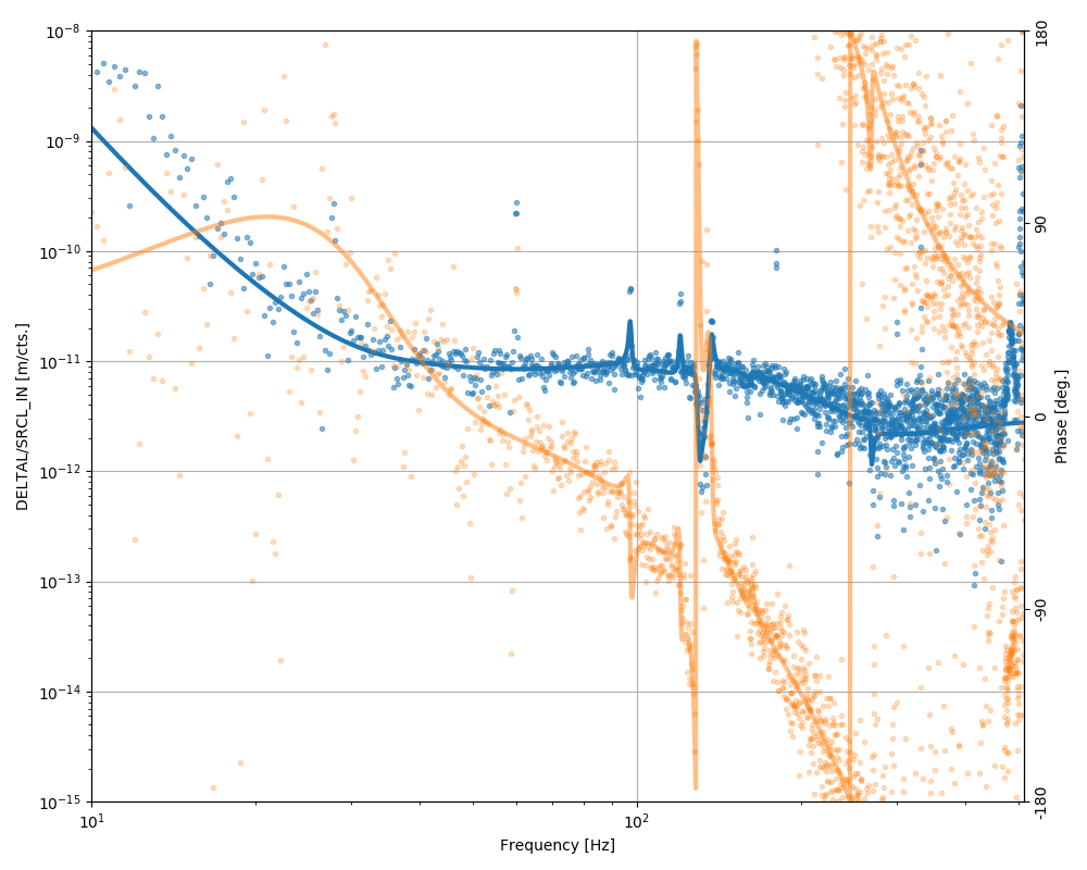
For now, since the linear term is still dominant, I restrict the analysis to a linear and stationary coupling from SRCL_IN to CAL-DELTA_EXTERNAL. Using 600 seconds of quiet data (no noise injection) starting at GPS 1228461018, I can reconstruct the optimal transfer function from SRCL to DARM in order to cancel out all of the SRCL noise. The plot below shows the result, the blue traces are absolute values (y axis on the left) and the yellow traces are phase (y axis on the right). The dots show the coupling factors computed in the frequency domain using the direct approach described in 45403. The solid lines are the "parametric" couplings: in other words the algorithm tries to minimize a weighted band-limited RMS in a band between 20 and 400 Hz, by modeling the coupling as stable, realizable 10th order rational function. To be clear, it's not a fit to the frequency domain reconstruction, but rather a direct fit to the data cross spectral densities.
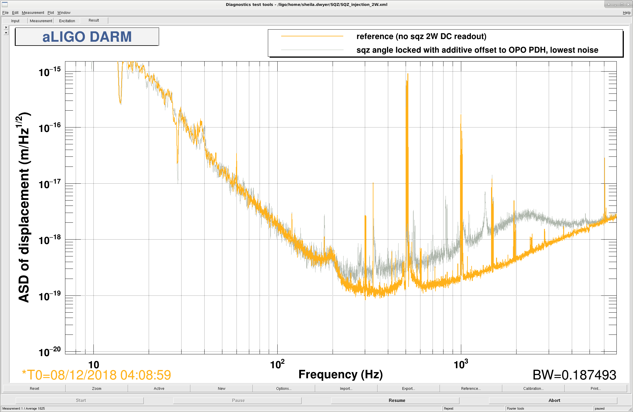
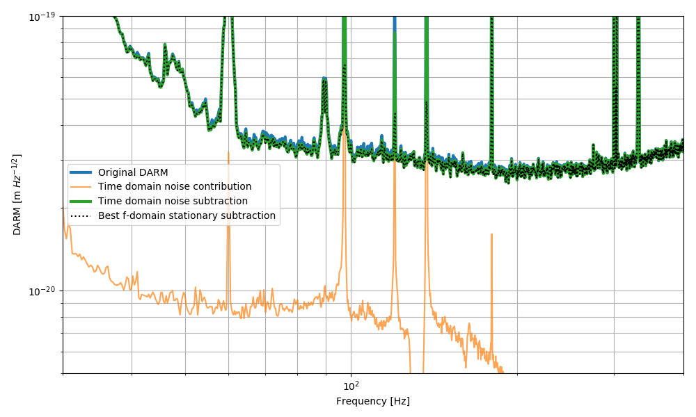
I can then convert the poles and zeros of this optimal coupling function to a IRR filter and perform a time domain subtraction. The result, shown below, confirms the level of SRCL noise in DARM predicted either by BruCO coherence 45785 or by Rana's injection 45792.
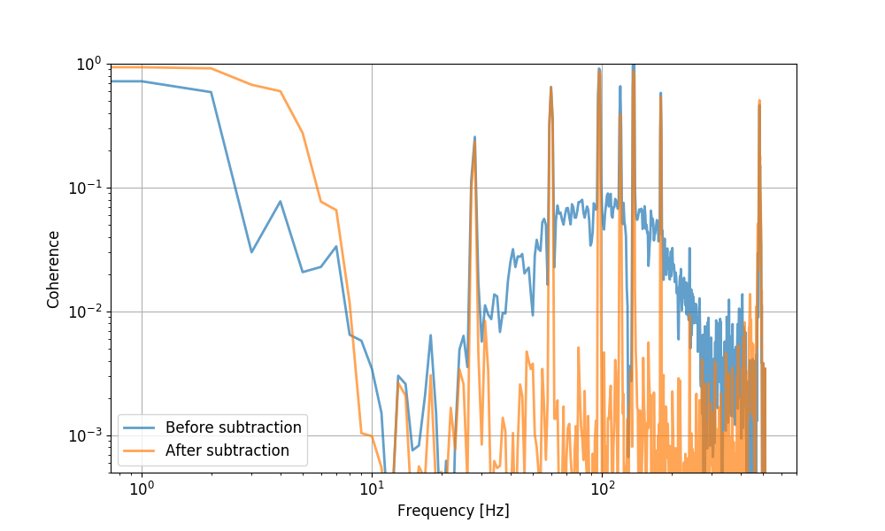
The last attached plot shows the coherence between DARM and SRCL before and after the time domain subtraction.
For reference, here's the transfer function from LSC-SRCL_IN1 to CAL-DELTAL_EXTERNAL (all poles and zeros frequencies in Hz). Note that both signals have been normalized by subtracting the mean value [mean(SRCL) = 0.00159, mean(DELTAL) = -9.800e-9] and dividing by the standard deviation [std(SRCL) = 3.131, std(DELTAL) = 1.503e-5):
Z =    [  73.27096456+274.9515352j ,   73.27096456-274.9515352j ,

          -1.09403038+269.468058j  ,   -1.09403038-269.468058j  ,

        -166.83658568  +0.j        ,   -0.8012538 +162.2435469j ,

          -0.8012538 -162.2435469j ,   -7.08797763+133.8045331j ,

          -7.08797763-133.8045331j ,   -3.15622979+134.12022151j,

          -3.15622979-134.12022151j,    0.9151632 +130.36107968j,

           0.9151632 -130.36107968j,   -1.42267922+119.98903183j,

          -1.42267922-119.98903183j,   -1.20138561 +97.64824832j,

          -1.20138561 -97.64824832j,   12.51635674 +30.96586879j,

          12.51635674 -30.96586879j,   27.66665614  +0.j        ]
P =    [  -2.14932791+268.49097597j,   -2.14932791-268.49097597j,

        -121.14272574+208.73233613j, -121.14272574-208.73233613j,

          -0.91968157+162.46027366j,   -0.91968157-162.46027366j,

         -51.9247949  +97.84796774j,  -51.9247949  -97.84796774j,

         -12.82120671+136.99086962j,  -12.82120671-136.99086962j,

          -0.96319905+136.92492285j,   -0.96319905-136.92492285j,

          -1.4837154 +128.24815143j,   -1.4837154 -128.24815143j,

          -0.60056718+120.09145053j,   -0.60056718-120.09145053j,

          -0.48652029 +97.30282541j,   -0.48652029 -97.30282541j,

         -15.69466233 +33.36645134j,  -15.69466233 -33.36645134j],
K = 3.079408216222647
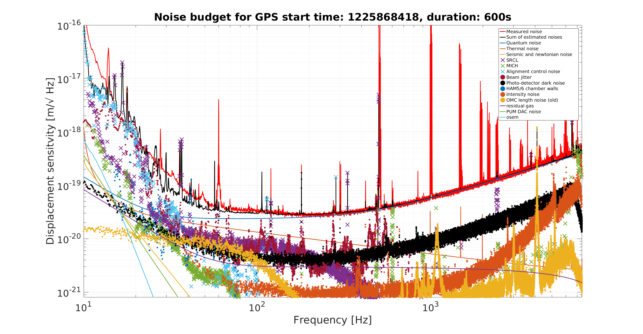
The SRCL projection in the noise budget was made when the SRCL FF was tuned for the correct DARM offset. On saturday night the DARM offset was changed and the SRCL FF was only adjusted with the scalar gain, 45782 so it is not surprising that the coupling is worse than in the noise budget.