Displaying reports 44101-44120 of 88591.Go to page Start 2202 2203 2204 2205 2206 2207 2208 2209 2210 End
Reports until 04:38, Tuesday 11 December 2018
H1 TCS
daniel.brown@LIGO.ORG - posted 04:38, Tuesday 11 December 2018 - last comment - 07:16, Tuesday 11 December 2018(45830)
ETM ring heater common change

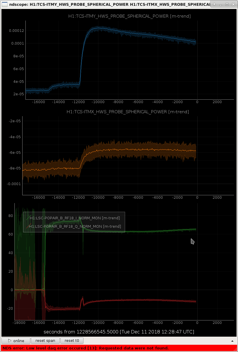
Tonight during the PI measurements we switched on the ETM ring heaters commonly to 2.5W. This made our arm-prc mode matching worse shown by a drop in the PRG.

During this time the ITMY HWS measured a reasonable drop in lensing, whereas ITMX did not, which has introduced a differential lensing. I'm not sure why ITMY has been so sensitive to this change. Currently we are down to about 45 and the arm power/RF18/PRG has become choppy looking, previously during large TCS changes when this has happened the choppiness has got worse and we lose lock more readily. However it looks like it might be leveling off around 45 now. Previously when dropping CO2Y power compared to CO2X I also a RF18 increase.

Images attached to this report
Comments related to this report
terra.hardwick@LIGO.ORG - 07:16, Tuesday 11 December 2018 (45832)

We did another step of both ETM RHs up to 4W total each at 14:22 UTC; all ETM RHs off at 15:14 UTC.

H1 ISC
sheila.dwyer@LIGO.ORG - posted 17:44, Monday 10 December 2018 (45827)
Intensity noise injections at different DARM offsets

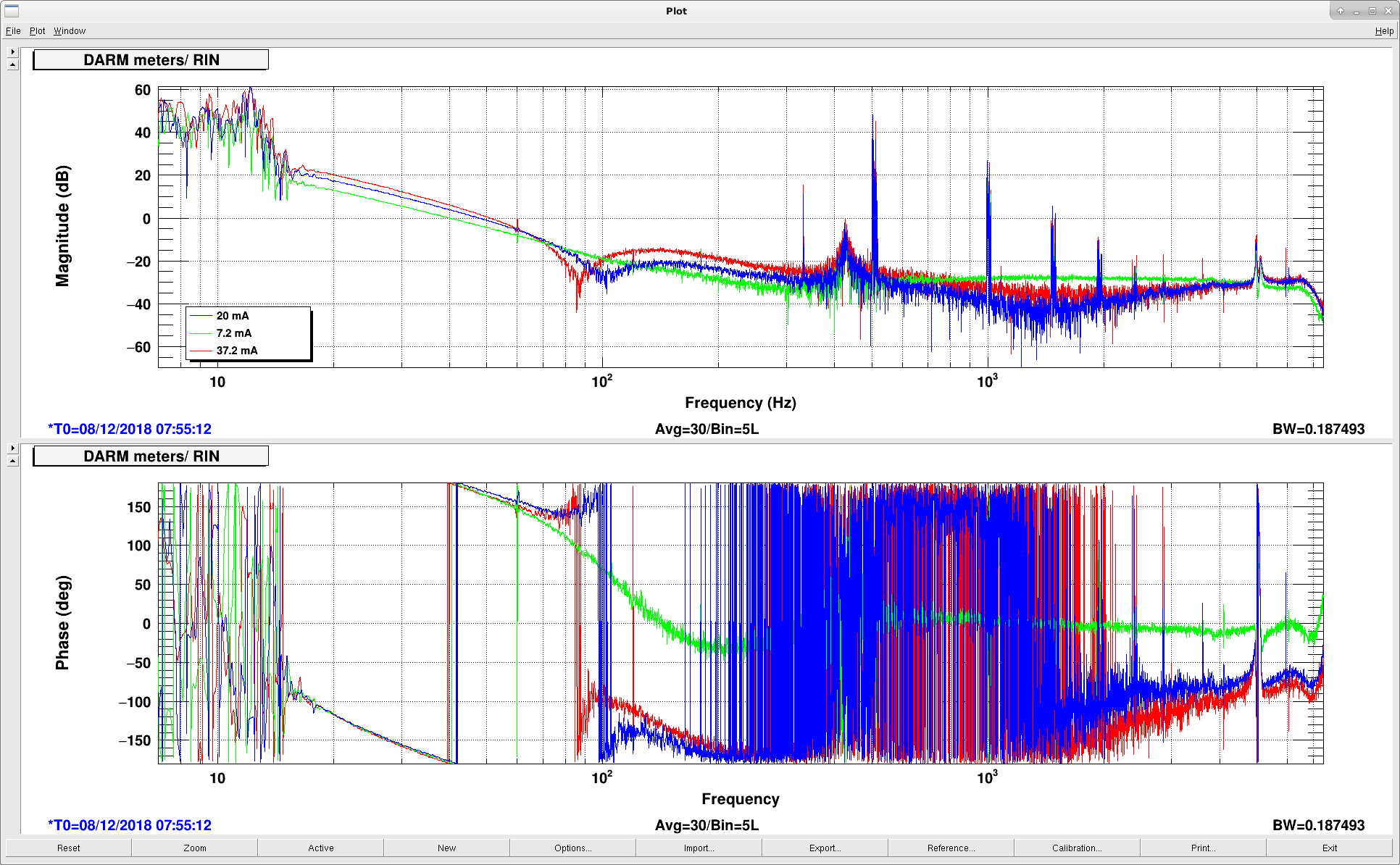
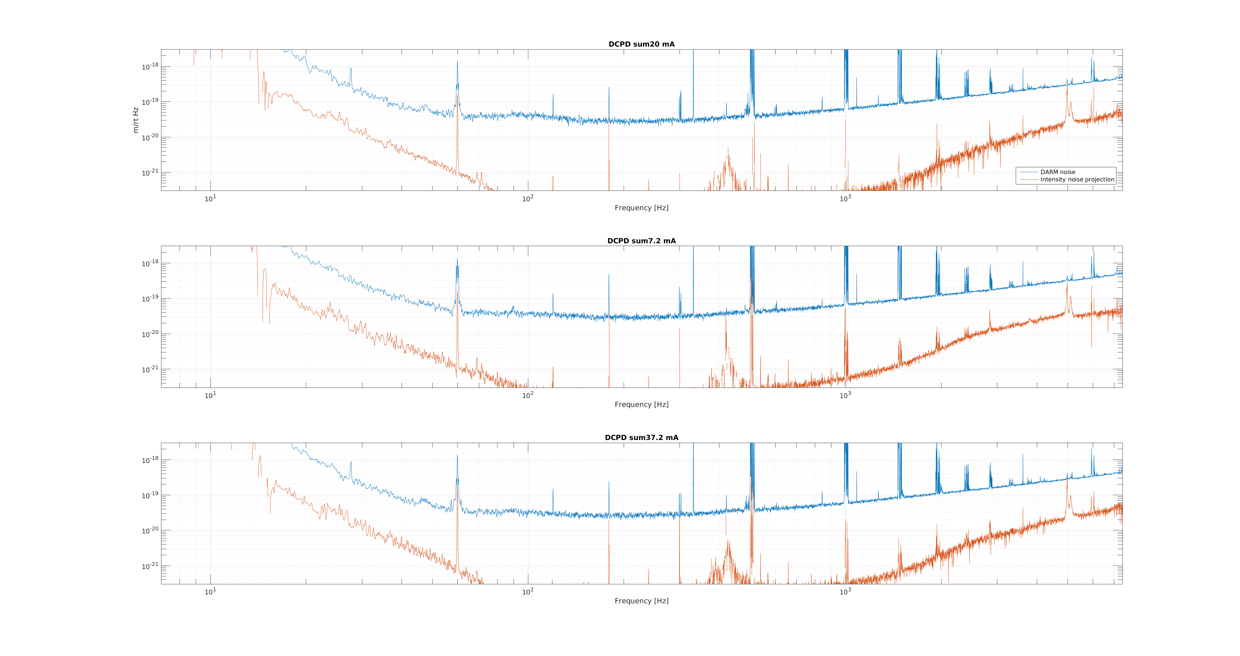
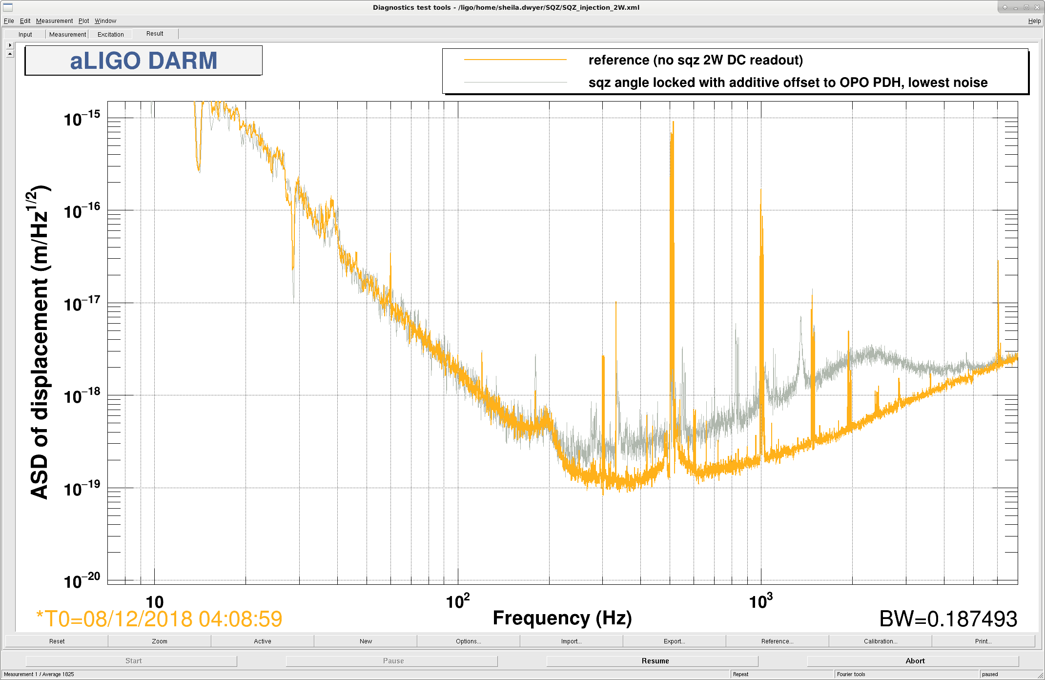
On Friday I did ISS injections at 3 different DARM offsets.  The change in the DARM noise for different DARM offsets can't be explained by these injections. 

The first attached plot shows the coupling from RIN on the ISS second loop (input beam) to mA on the DCPDs for the three different DARM offsets. At high frequencies the transfer functions from RIN to mA would be the same for different DARM offsets if the intensity noise was coupling through contrast defect light.  

The second attached plot shows intensity noise projections for all three DARM offsets.  I didn't correct the optical gain in the calibration for the 7.2 and 37.2 mA plots, so the calibration is off.  In any case, these projections are at least a factor of 10 below DARM.  This doesn't rule out intensity noise on the sidebands.  

For those who are interested the times of these injections are:

UTC times, December 8th 2018

20mA Injection:  7:55:12 quiet time: 7:49:44 

7.2 mA Injection: 7:59:26 UTC quiet time: 8:00:36

37.2 mA Injecton: 8:02:54 UTC quiet time: 8:04:25

Images attached to this report
H1 ISC (DetChar)
gabriele.vajente@LIGO.ORG - posted 16:41, Monday 10 December 2018 - last comment - 03:39, Tuesday 11 December 2018(45823)
SRCL non-stationary noise coupling

Summary

This is an update on my previous activity on the characterization and subtraction of the non stationary SRCL coupling. See 45403 and 45508 for an introduction to the problem and methodology. In those elogs I developed a frequency domain method to compute how ASC signals modulated the SRCL to DARM noise coupling. In addition to that technique, I now have a parametric algorithm, that is capable of directly finding the optimal parameters to be used to implement stable and realizable time domain subtraction filters. For those of you familiar with Wiener filtering, this technique can be viewed as an IIR Wiener filter that also includes noise coupling modulations. More details on this technique are available in the DCC T1800525.

Here, instead of using the same data that I analyzed for 45403 and 45508, I used Rana's noise injection (45803 and 45792). In 45803 I derived the optimal filter to subtract the stationary coupling from SRCL_IN to CAL-DELTAL_EXTERNAL, using data without any noise injection. Here instead I used 150 seconds of data starting at GPS 1228458231 while there was a SRCL noise injection. My algorithm was tuned to use 16th order coupling transfer functions, and all ASC input signals as modulation sources.

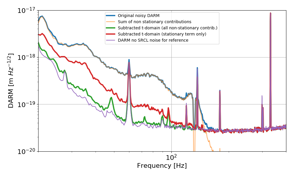
First of all, the money plot. The blue trace is the CAL-DELTAL spectrum during the SRCL noise injection, while the purple line is a reference from a few minutes before that, when there was no injection. The red trace is the best subtraction we can obtain using only the static, linear transfer function from SRCL_OUT to CAL-DELTAL. The green trace instead is the level of subtraction we can achieve including all non-stationary contributions. It is quite close to the DARM noise floor. The SRCL noise coupling reduction we obtain here is somewhat lower than what I could obtain in 45508: my guess is that is due to the fact that the SRCL injection was not as strong as the one that I did, so there was not enough SNR to extract even lower modulated contributions.

Nevertheless, by including the non-stationary contribution we can gain a factor of a few subtraction at all frequencies.
 

More details below

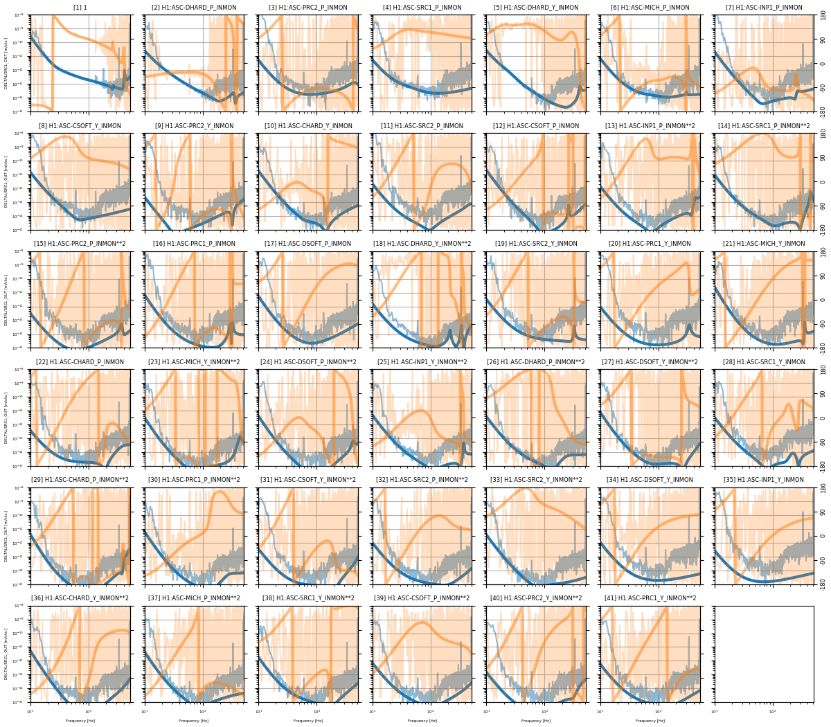
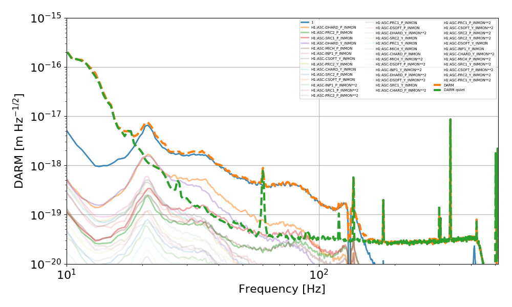
The plot below shows the reconstructed coupling transfer functions. Each panel correspond to one noise source, i.e. SRCL_OUT multiplied by the ASC signal in the title (where '1' means just a constant signal equal to one, that is, the stationary channel). The noisy traces in the background are the frequency domain direct solutions, while the solid smooth traces are the 16th order transfer functions obtained with a special s-domain transfer function parametrization that enforces the pole stability (and causality). The blue traces are the absolute values (refer to the left y axis) and the orange traces are the phases (refer to the right y axis).
 

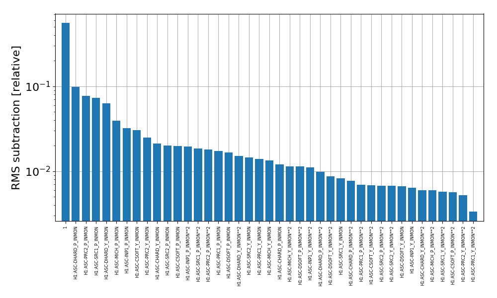
The contributions are sorted based on a ranking which computed what is the contribution of each modulation to the total noise subtraction, integrated between 10 and 400 Hz in this case. The numerical ranking of each ASC channel is reported below
 

Another way to look at this is to plot each contribution in a spectrum of DARM, as below:
 

Images attached to this report
Comments related to this report
rana.adhikari@LIGO.ORG - 03:39, Tuesday 11 December 2018 (45829)DetChar, ISC
  • Getting an extra factor of 3 would be very valuable. The SRCL loop has only 15 deg off phase margin if we lower the UGF to 10 Hz and a little gain fluctuation would probably cause a lock loss. It would be more comfortable to have a 20 Hz UGF.
  • I wonder if this technique would also allow to track long term drifts? We should turn a line on in SRCL2_EXC and see how the long term subtraction works.
  • Perhaps we can get more cleaning out of the O2 data by trying this out? There may be stretches of data from Aug 2017 with anomalously high SRC coupling that could be mitigated. Even if we don't get an online version of this working before O3, we could find a way to add it to the data cleaning toolbox.
H1 CDS (CDS, ISC)
keita.kawabe@LIGO.ORG - posted 16:34, Monday 10 December 2018 - last comment - 06:02, Thursday 13 December 2018(45825)
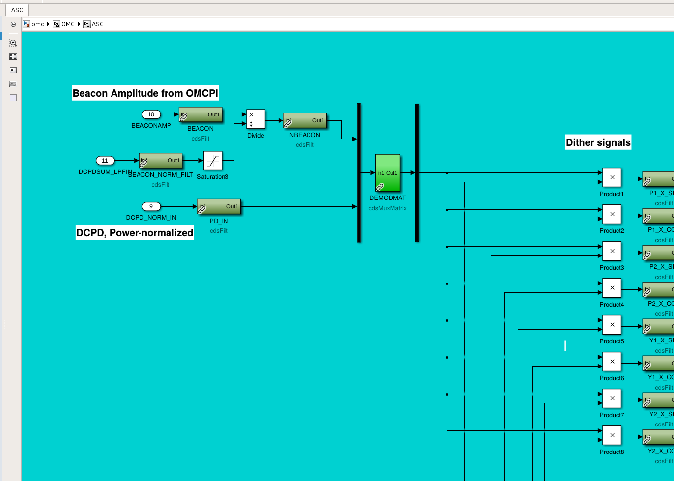
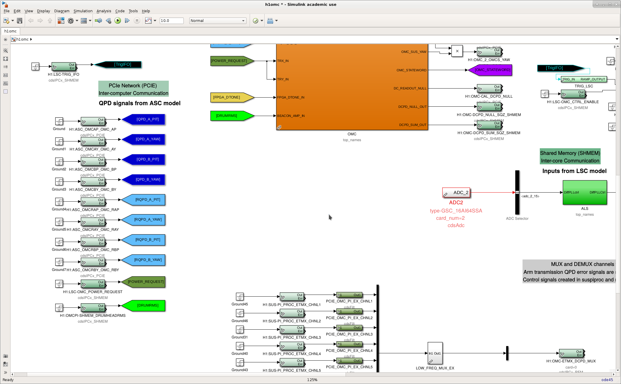
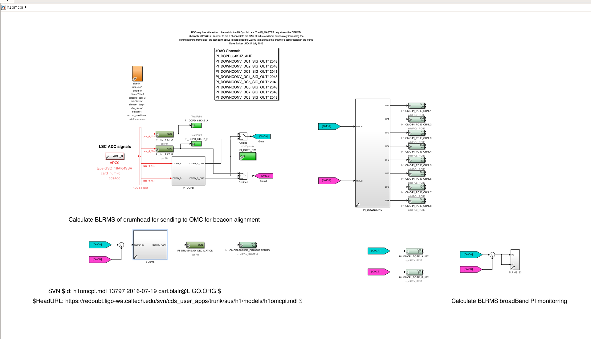
preview of omc and omcpi model change for drumhead beacon dither

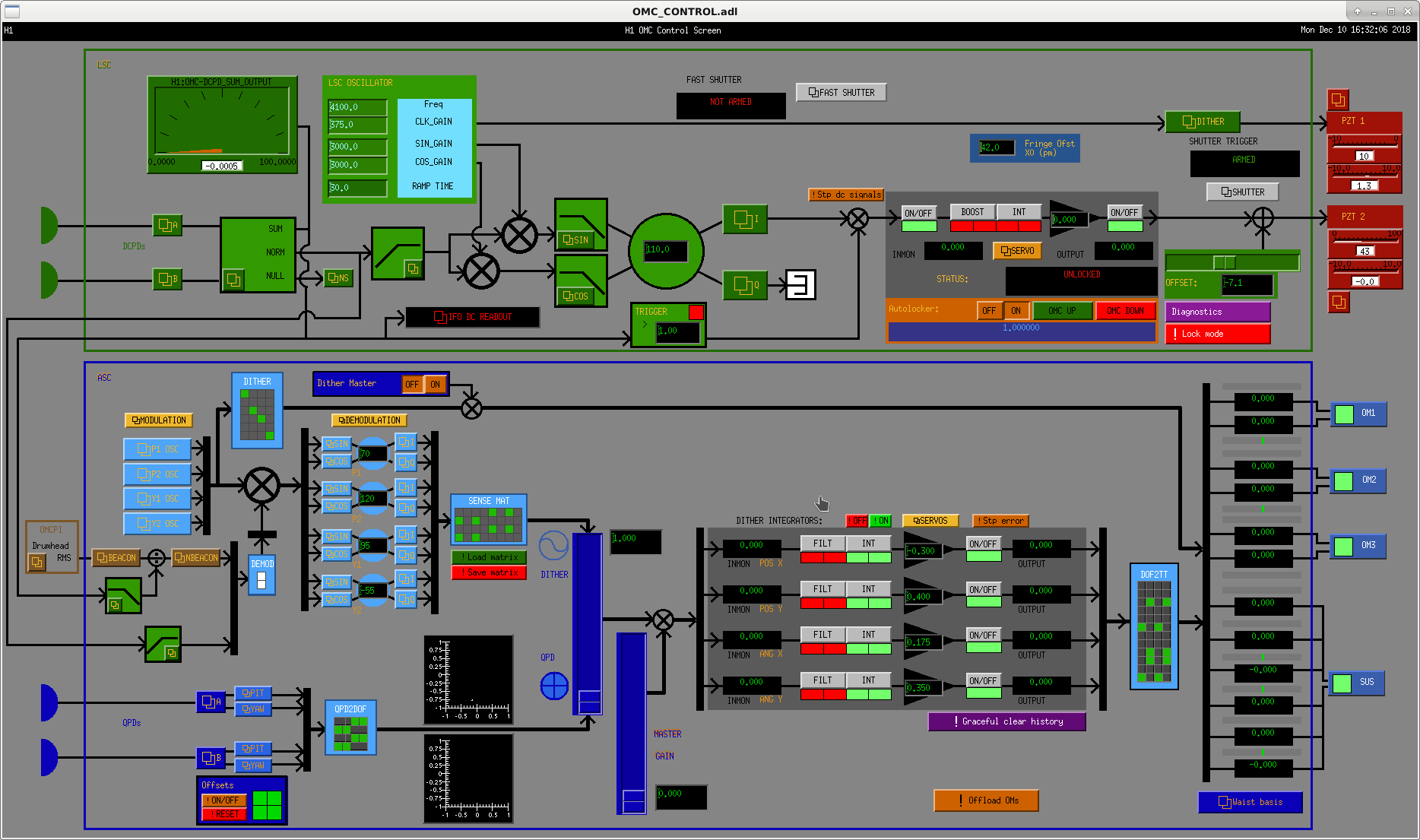
h1omcpi and h1omc were changed and compiled but not installed (that's for Tuesday).

In h1omcpi, a decimation filter was put between the drumhead mode RMS (64kHz) and shared memory as the omc model works at 16kHz.

Alignment dither oscillators are common for deacon and normal dither. An input matrix is used for selecting the source of demod. This makes it cumbersome to switch between low frequency dither for deacon and high frequency dither for normal dither, but once deacon works it won't be an issue.

WP7995

Images attached to this report
Comments related to this report
keita.kawabe@LIGO.ORG - 16:42, Tuesday 11 December 2018 (45852)

Done.

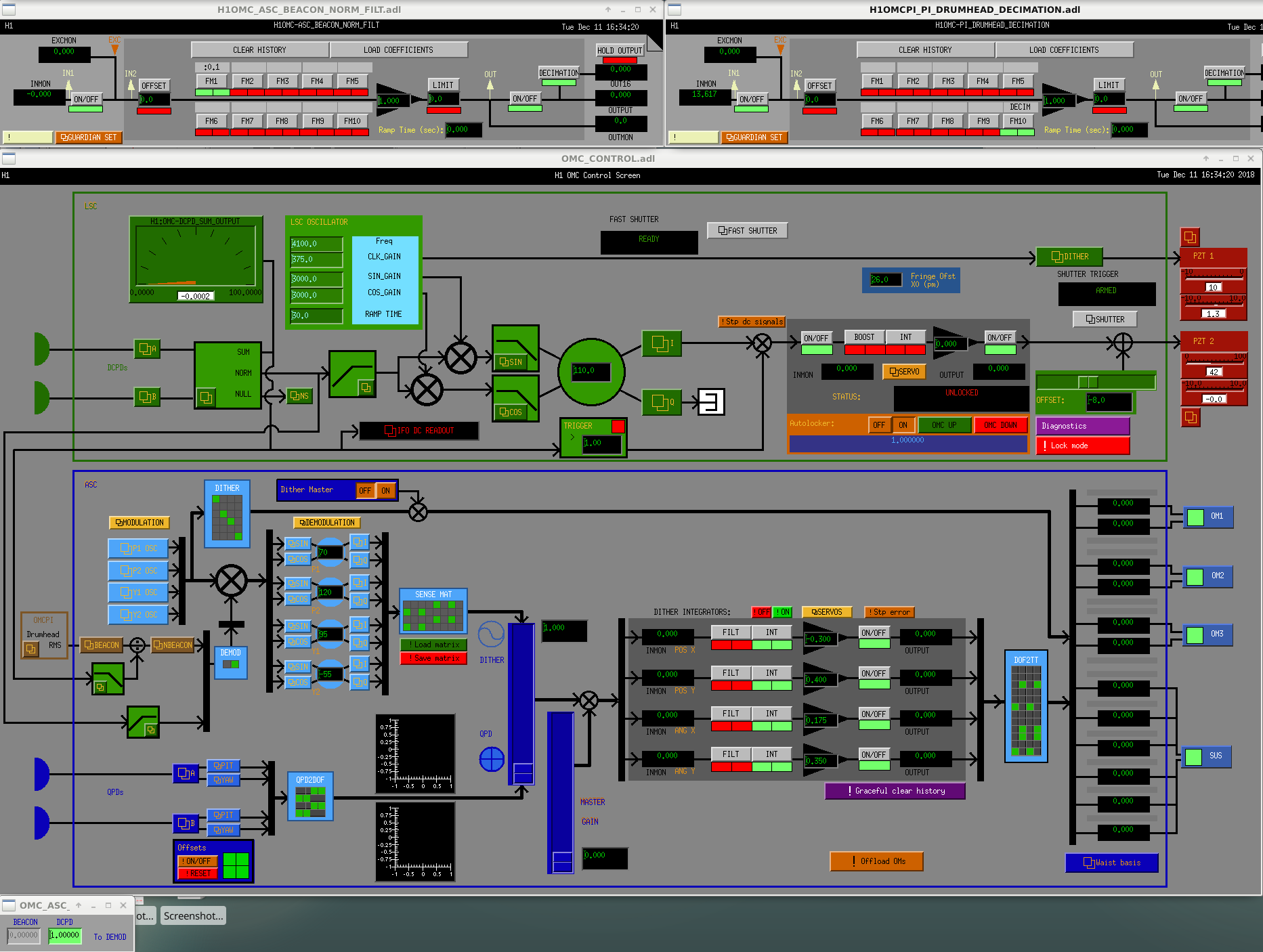
For now demod matrix is set up to use old dither (H1:OMC-ASC_DEMODMAT_1_1=0, H1:OMC-ASC_DEMODMAT_1_2=1).

Assuming that deacon needs dithering on the order of Hz, I put a 3rd order Butterworth LP at 0.1Hz for power normalization.

For passing drumhead RMS from 64kHz to 16kHz frontend, I used an equivalent of x4 decimation filter in  T1600059 (but the data rate is 64kHz), in this case ellip("LowPass",6,0.3,60,7372.8).

Images attached to this comment
terra.hardwick@LIGO.ORG - 06:02, Thursday 13 December 2018 (45901)

I've populated the control filters in OMC_CUST_DRUMHEAD_EXC with bandpasses around each drumhead mode (I've not set up any of the other control filters). I also cleaned up that medm screen a bit so that drives now go to all test masses correctly. In the main PI screen, I've allocated and set up the 8th downconversion and upconversion blocks for these drumheads. If I populate the BEACON_DRIVE_MTRX, I see signal in the PI drive channels, but I haven't tested beyond that yet.

Modes are: ITMX 8156.7 (A), ITMY 8163 (B), ETMX 8158.6 (C), ETMY 8153.5 (D)
H1 CDS (TCS)
david.barker@LIGO.ORG - posted 16:31, Monday 10 December 2018 (45824)
h1tcscs EPICS input mechanism changed, ring heater inverse filtered by model

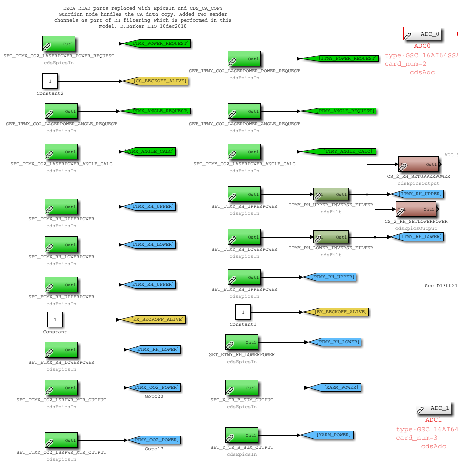
WP7997: inverse ring heater filters added to h1tcscs, output sent to Beckhoff

WP7996: replace model ezca(read,write) parts with EPICS parts, CDS_CA_COPY guardian node handles data transfer

Danni, TJ, Dave:

h1tcscs model was changed to:

replace all existing EzCaRead parts with EpicsIn parts

add two filters for ITMY_RH_[UPPER,LOWER]_INVERSE_FILTER

send the output of the two new filters to EpicsOut parts

See attachment for simulink model details.

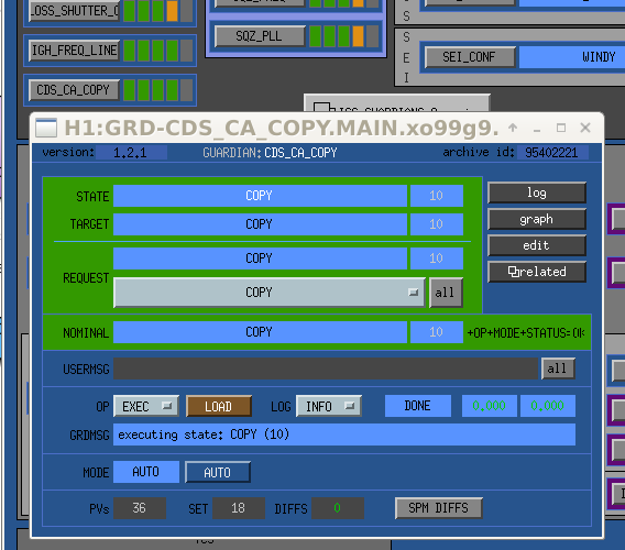
TJ created a new Guardian node called CDS_CA_COPY which will handle all EPICS Channel Access copies between front end models and slow controls IOCs.

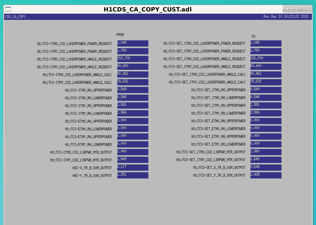
The initial CDS_CA_COPY is just copying the input SET channels to h1tcscs. We will expand it to other copies later, including replacing the current camera_copy script.

The Guardian MEDM and the new H1CDS_CA_COPY_CUST.adl are shown in attachments. The latter is accessed via SITEMAP->CDS

Images attached to this report
LHO General
corey.gray@LIGO.ORG - posted 16:01, Monday 10 December 2018 (45801)
DAY Operator Summary

TITLE: 12/10 Day Shift: 16:00-00:00 UTC (08:00-16:00 PST), all times posted in UTC
STATE of H1: Commissioning
INCOMING OPERATOR: None
SHIFT SUMMARY:

Able to get some time/experience with locking (notes below).  There were some model changes for TCS & Guardian (+ DAQ restart) to aid with overnight AMD measurements.

My Operator Locking Notes Today

LOG:

H1 SUS (SUS)
patrick.thomas@LIGO.ORG - posted 15:05, Monday 10 December 2018 (45818)
Added 2nd harmonic violin mode filters
Patrick, Jenne

I have added filters for the second harmonic violin modes to the mode 11 - 17 filter banks for ITMX, ITMY, and ETMX, and the mode 11 - 15 filter banks for ETMY. I have also updated lscparams.py to set these, with the max gain for all of them set to 0 for now.
H1 IOO (IOO)
cheryl.vorvick@LIGO.ORG - posted 15:03, Monday 10 December 2018 - last comment - 15:18, Monday 10 December 2018(45817)
Locking issues Sunday related to IM2

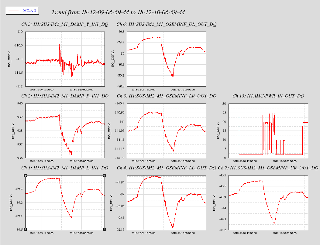
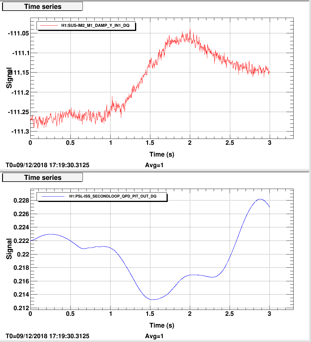
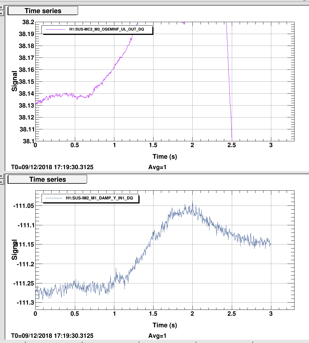
IM2 starts during 9 dec 2018 17:19:26, GPS  1228411184, and it continues to move  away from nominal until around 21:00, and recovers to a reasonable alignment 23:30:

MC1 also has a glitch, which in diaggui looks to start after IM2.

Attached Plots:

Images attached to this report
Comments related to this report
cheryl.vorvick@LIGO.ORG - 15:10, Monday 10 December 2018 (45820)

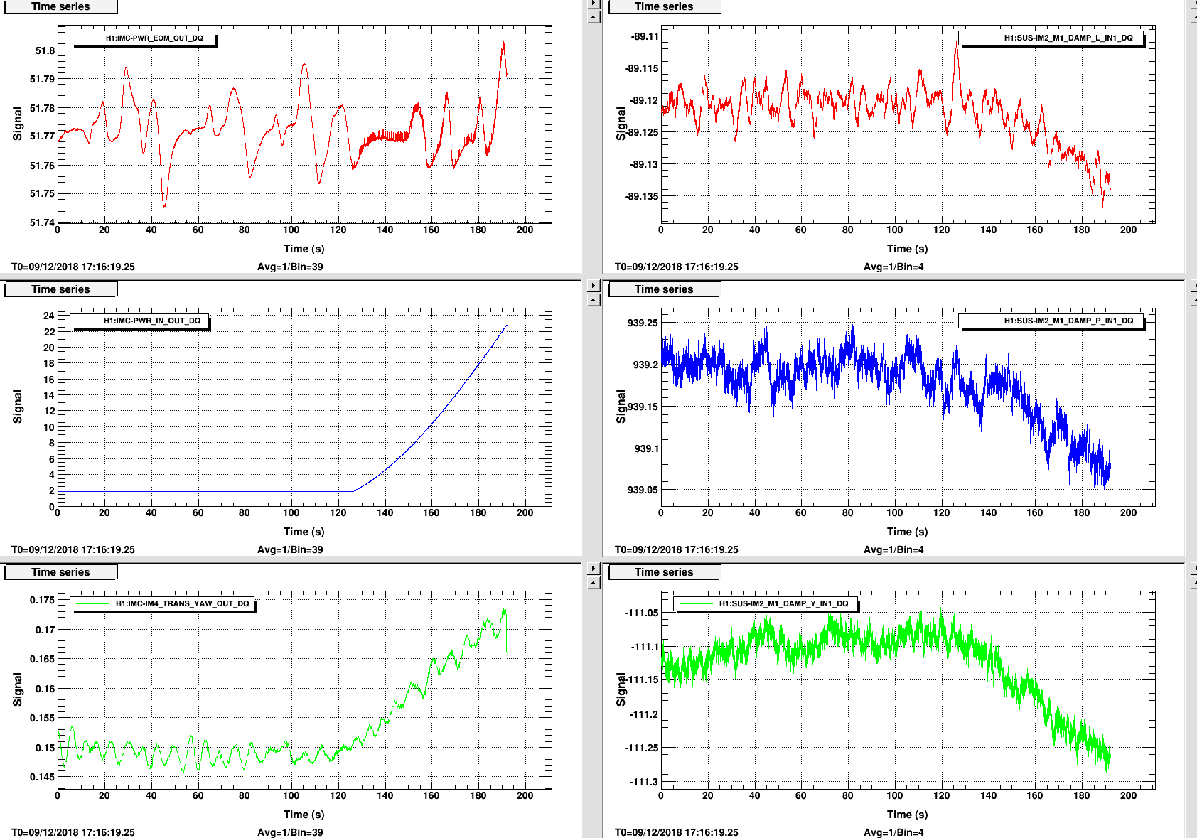
CHANGE IN ALIGNMENT WITH POWER UP: (just before glitch)

Images attached to this comment
cheryl.vorvick@LIGO.ORG - 15:16, Monday 10 December 2018 (45821)

EOM OUT AND PMC TRANS GLITCH AND SHOW LEVEL CHANGES WITH ROTATION STAGE MOTION: (beams seen on PMC Trans face, and beam from the IMC has been located on the PSL, so it seems some light is getting back into the PMC.

Images attached to this comment
cheryl.vorvick@LIGO.ORG - 15:18, Monday 10 December 2018 (45822)IOO

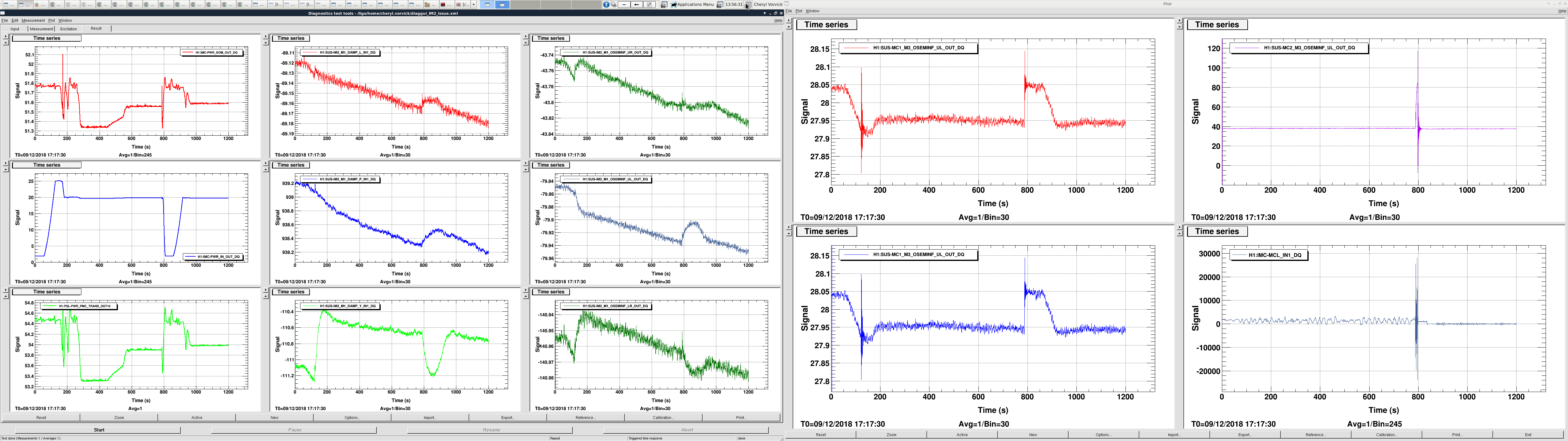
Multiple power up/down cycles, showing IM2 and MC1 alignment.

Images attached to this comment
H1 AOS
jim.warner@LIGO.ORG - posted 12:08, Monday 10 December 2018 (45815)
HAM sensor correction update needs a work-around

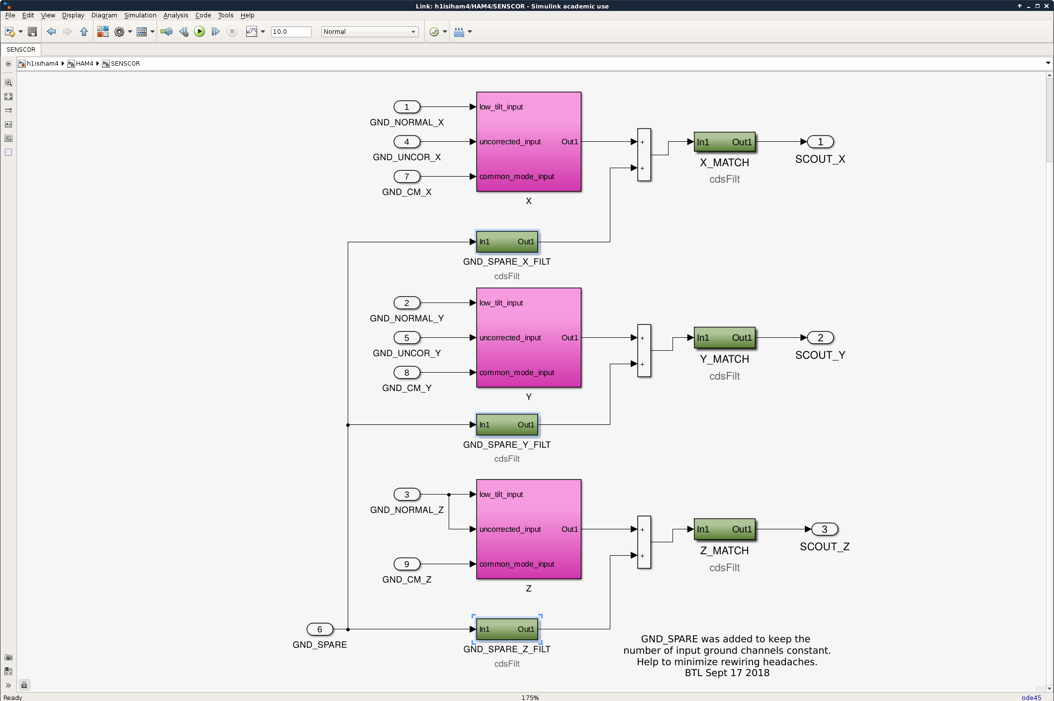
The HAM & HEPI models are supposed to get an update similar to the one the BSCs got last week, but unfortunately the new code didn't include a path for the GND Z to HAM4 Y sensor correction that I put in last week. I have a workaround, but it's not as flexible as the set up we currently have. The current model uses a 9x6 sensing matrix that lets us route any DOF of the 3 corner STS2s to any X/Y/Z of the corner chambers just by changing an epics value, but the new update eliminates that sensing matrix. There is, however, an unused spare input which I luckily have opted to send the GND Z signal into all models, because it was easy. This spare signal used to just get grounded inside the sensor correction block, but now I would like to send this spare channel through a filter bank and sum it with the output of each of the new X/Y/Z sensor correction paths as shown in my attached screenshot. The GND_SPARE_DOF filter banks are the new stuff. This limits me to using whatever signal I send into the spare path at the top level of the model, and if that needs changed, it will require a model change.But so far, I only need the GND Z to HAM4 Y path. 

Images attached to this report
H1 ISC
terra.hardwick@LIGO.ORG - posted 11:17, Monday 10 December 2018 (45812)
mechanical mode Qs with AMDs, 2W

Seb, Terra

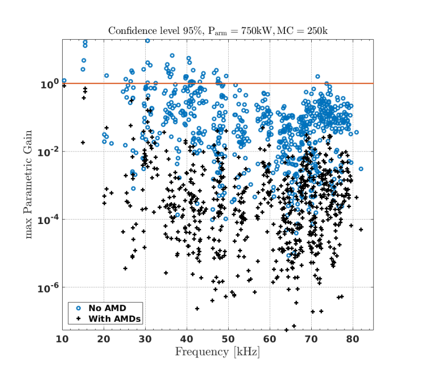
Thanks to Craig and Dan's dedicated locking efforts last night, we've measured a full suite of test mass mechanical mode Qs post all AMDs. Results hereWe see reduction of Q for all modes above 9kHz; 15 kHz modes see reduction factors of at least factor of 10. Measurements done at 2 W input power for least parametric gain contribution and consistency with the few pre-AMD measurements we have.

Reminder that parametric gain Rm ~ QmParm where Qm is quality factor of the mechanical mode, Parm is the power in the arm cavity, Rm > 1 is unstable. In the attached table, we note pre-AMD Qs from what measurements I could find quickly from the last two years. The last column shows predicted Qs from sec 4.11 in Seb's thesis (note these differ from the predicted Q's in 38129 as the latter were before a change in the modeling of the epoxy layer realized after the results of the ETMX AMD test). I also attach the modeled max parametric gains at Parm = 750 kW pre and post AMDs from Seb's thesis to give some context.

To check if modes at 23kHz are aliased, we checked the frequency shift over a 4 hour lock and all but one look to be not aliased (they slightly increased in freq along with drumhead modes). 

We have a few anomalies/poor fits that we'll try to remeasure in the next few nights. 

Images attached to this report
Non-image files attached to this report
H1 SUS (CDS, ISC, SUS)
jeffrey.kissel@LIGO.ORG - posted 10:54, Monday 10 December 2018 (45813)
H1SUSETMX PI Front-End Code Changed to Recognize 20 bit DAC
D. Barker, S. Biscans, T. Hardwick, J. Kissel
WP 7994

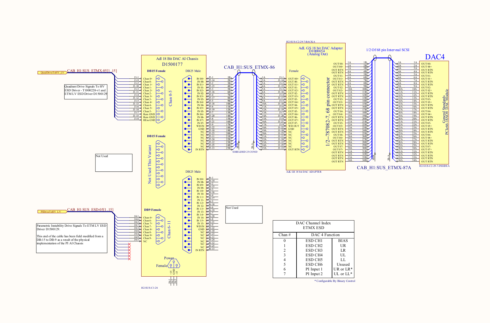
Terra and Sebastien discovered that when we upgraded the SUS ETMX I/O chassis to use a 20-bit DAC (LHO aLOG 44905), and upgraded the h1iopsusex and h1susetmx models accordingly (LHO aLOG 44918), we forgot to upgrade the front-end model for parametric instability (PI) drive, i.e. h1susetmxpi, in order to recognize it.

This was a quick and easy change to the front-end model (see before vs. after screenshots below, plus the electronics wiring snippet from D1400177), which we installed immediately this morning. No DAC restart was needed, nor did it impact the IFO.

After the install, Terra and Seb have equally quickly confirmed that the drive system is now functional.

The updated simulink model has been committed to the userapps repo:
    /opt/rtcds/userapps/release/sus/h1/models/h1susetmxpi.mdl
Images attached to this report
H1 ISC (ISC)
rana.adhikari@LIGO.ORG - posted 23:37, Sunday 09 December 2018 - last comment - 18:45, Monday 10 December 2018(45792)
SRCL Noise coupling again

I was skeptical about the SRCL noise in the noise budget, so I checked it again. I think it is pretty close.

Its a simple method, but should be accurate. SRCL_FF left on in the Guardian set state in NLN.

  1. Turn on broadband noise excitation in SRCL2_EXC with AwgGui.
  2. Adjust calibration of SRCL_OUT in DTT until the SRCL_OUT trace matches DARM.
  3. turn off excitation to see how the ambient SRCL compares to DARM.

From this exercise I get the attached plot. Looks like its very close in the 40-90 Hz band. Options:

  1. better low pass filtering; Downside: this is hard and will make the loop more unstable.
  2. lower the SRCL gain: could be fine, but we don't yet know what the allowed SRCL error signal fluctuations are. i.e., how much can the SRC length fluctuate before it goes nonlinear or ruins the WFS signals?
  3. improve the sensing noise: more power, more modulation depth, less electronics noise. Do we have a SRCL noise budget?
Non-image files attached to this report
Comments related to this report
peter.fritschel@LIGO.ORG - 06:50, Monday 10 December 2018 (45797)

Why does this look so different than the SRCL contribution in the noise budget in entry 45169 , which was made just after the SRCL and MICH feed-forward was improved? In that NB the SRCL noise goes below 1e-21 strain/rtHz just above 70 Hz, while in this one that doesn't happen until 300 Hz. Has something in SRCL changed (loop gain, filters?) or is the Nov 9 NB thought to be in error?


gabriele.vajente@LIGO.ORG - 07:27, Monday 10 December 2018 (45798)

This is consistent with the BruCo projection based on coherence between DARM and SRCL. See https://alog.ligo-wa.caltech.edu/aLOG/index.php?callRep=45782

And also consistent with the level of cancelation you can get by linear noise subtraction ( will post more later on this)

sheila.dwyer@LIGO.ORG - 09:00, Monday 10 December 2018 (45805)

On Saturday night the DARM offset was changed and the SRCL FF wasn't re-tuned, so you would not expect this to match the noise budget.  I don't know if these changes were in place last night.

craig.cahillane@LIGO.ORG - 15:13, Monday 10 December 2018 (45819)
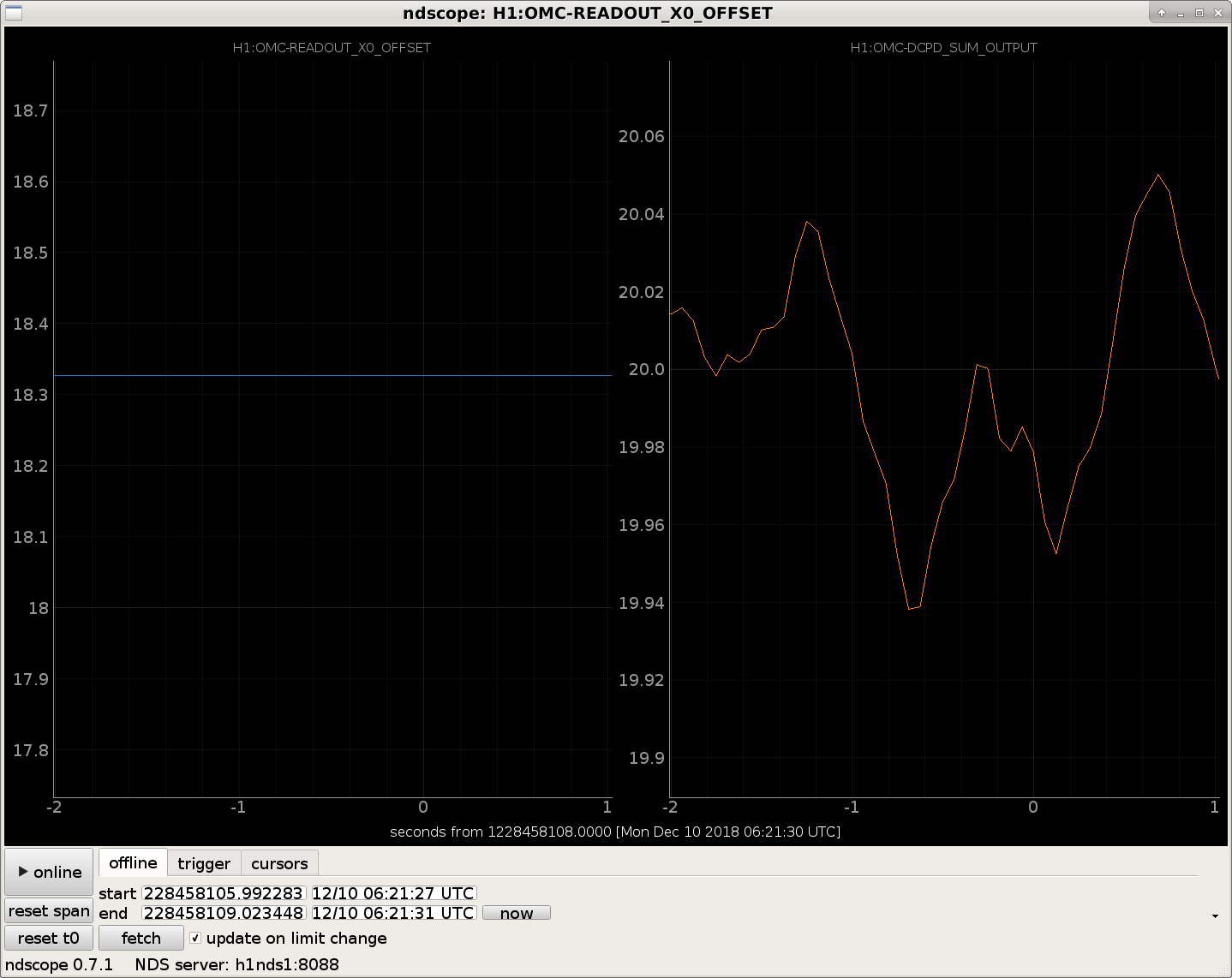
The DARM offset during this measurement was 18.3 cts (~12 pm), giving 20 mA (23.8 mW) of power on the OMC DCPD SUM channel.  
Guardian is the one who controls the DARM offset during the INCREASE_POWER and ADJUST_POWER state, so it always sets it to whatever gives 20 mA on the DCPDs.
It's possible the SRCLFF needs to be retuned after the vent.  However, I doubt it will improve the SRCL to DARM by more than a factor of 2 or so (i.e. our current SRCLFF is decent).
Images attached to this comment
sheila.dwyer@LIGO.ORG - 18:45, Monday 10 December 2018 (45828)

Here is a noise budget where only the SRCL noise is updated, taken today.  (With 20mA DCPD sum at 20 W input power). The SRCL FF hasn't been returned since the TCS changes, that seems to explain the larger coupling. 

Images attached to this comment
H1 ISC
stefan.ballmer@LIGO.ORG - posted 21:42, Saturday 08 December 2018 - last comment - 13:31, Monday 10 December 2018(45782)
H1 joins the Holiday Party

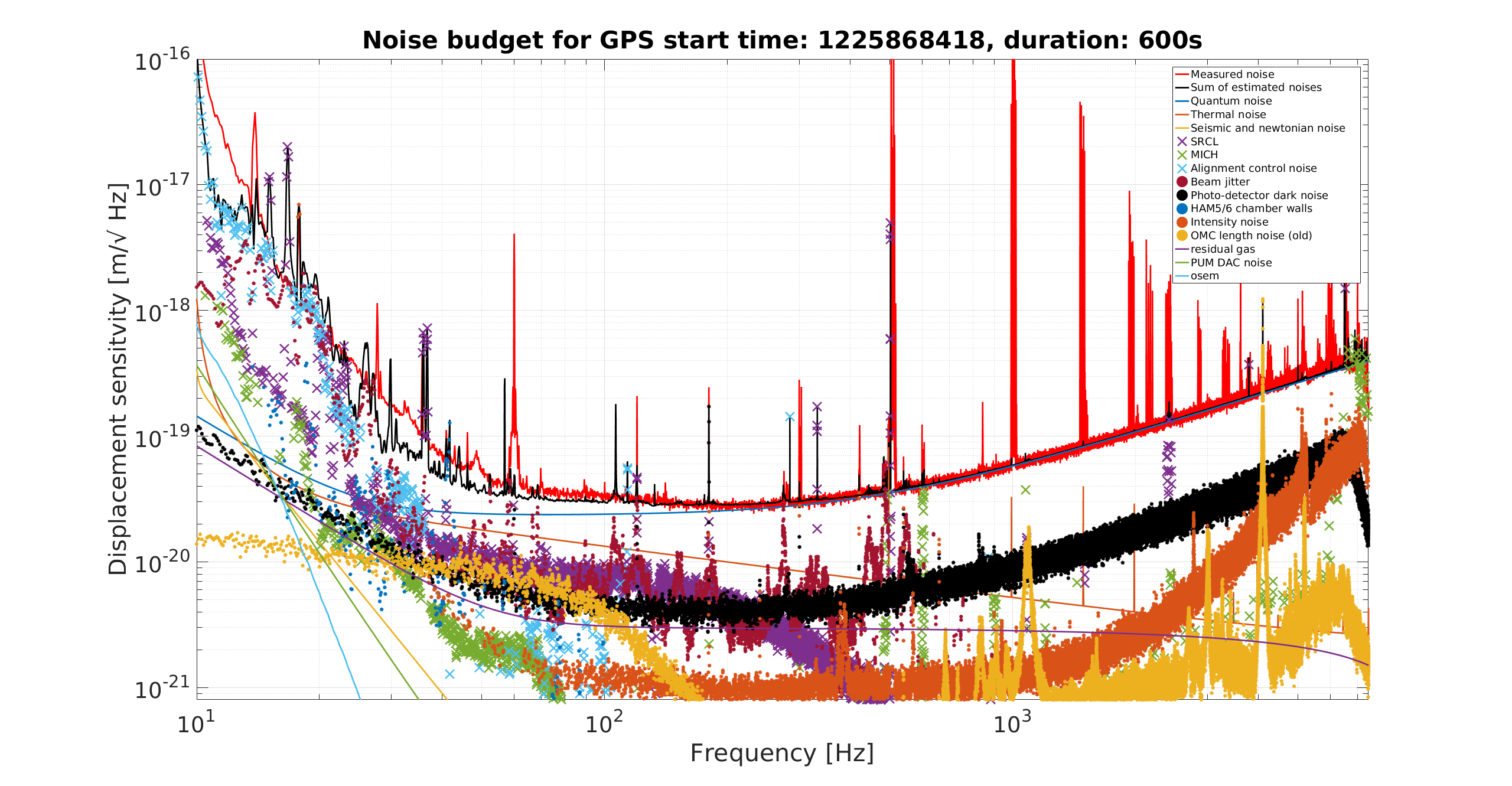
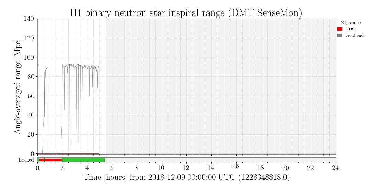
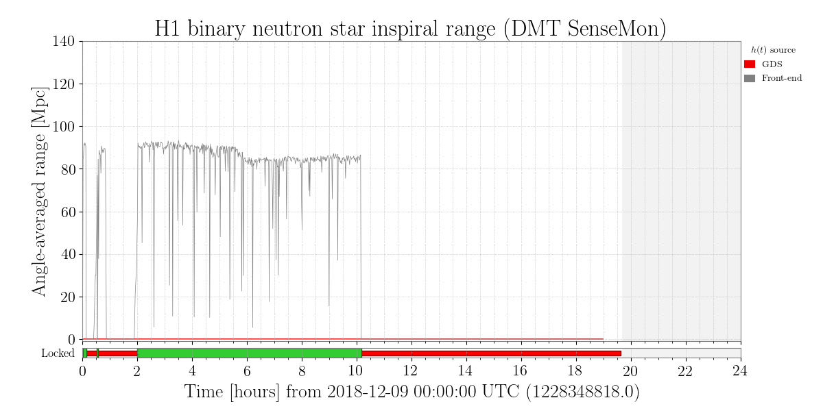
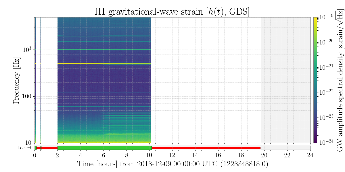
Since everybody went to the holiday party tonight, I left the interferometer in low noise. After guardian was done, I punched up the input power to 25W (without reducing the DARM offset, i.e. letting the OMC current grow to 25mA), and then increased the DARM offset by another 9% (~30mA). Finally, I blindly increased the SRCLFF by 9% (punching in 1.09 in the gain), and left it there.

Looks like the machine sat there stably at 90Mpc for the whole holiday party... Merry Christmas!

Images attached to this report
Comments related to this report
andrew.lundgren@LIGO.ORG - 13:31, Monday 10 December 2018 (45816)DetChar, ISC, SUS
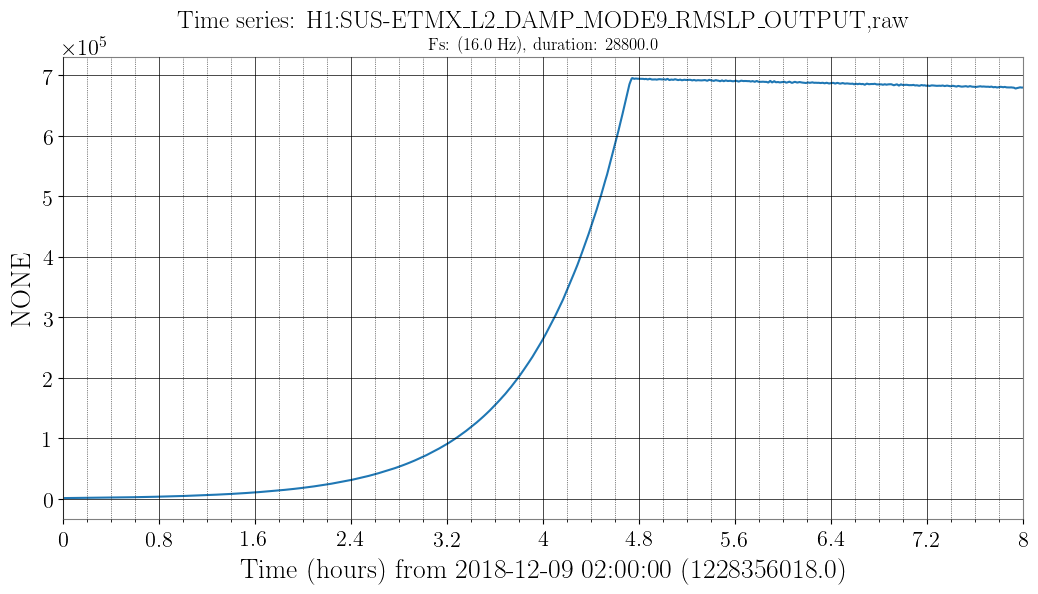
The period of bad data looks to be due to a ringup of a violin mode fundamental at 516.78 Hz (ETMX mode 9). It goes up in amplitude by a factor of ~60 and becomes the largest signal on the DCPD.

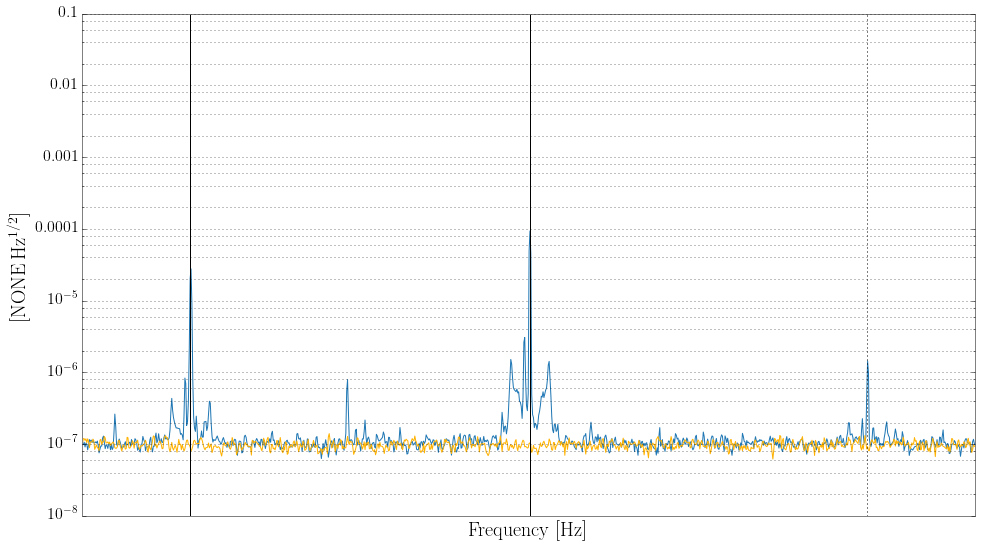
Once the mode becomes large enough, some nonlinearity makes a forest of lines at low frequencies, and multiples of the violin mode show up throughout the spectrum (plus an associated forest of lines). There are also lines 6.07 Hz above and below each multiple, which I think are caused by beating against 510.71 Hz. This is ETMY mode 1 according to MEDM, and it's also high but not growing during the lock.

The nonlinearity becomes a problem around 5:50 UTC, when the violin mode monitor goes above 2e5 counts, see first plot. A spectrum around the line at 3*516.78 Hz is the second plot, with the lines at 6.07 Hz above and below also marked.

These violin modes and their ID are given in alog 43661, though the 510 Hz line since seems to have been identified as ETMY rather than ETMX.
Images attached to this comment
gabriele.vajente@LIGO.ORG - 12:05, Sunday 09 December 2018 (45785)

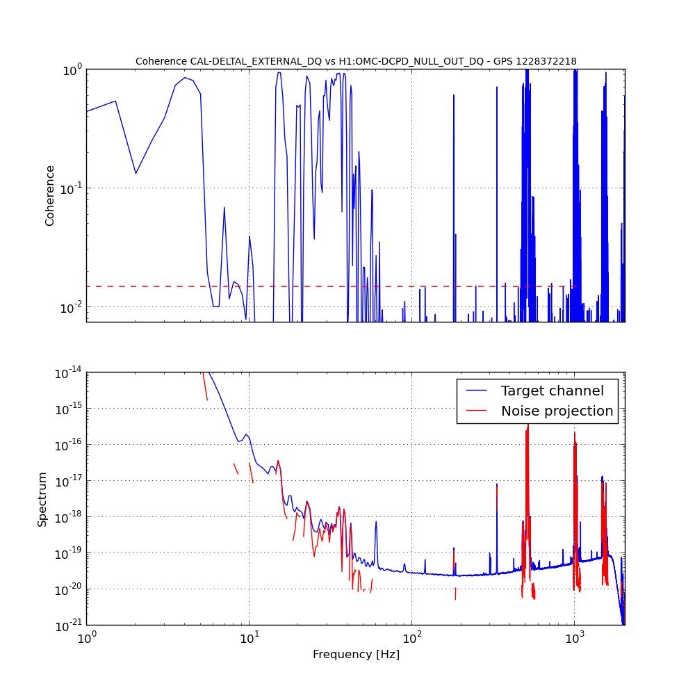
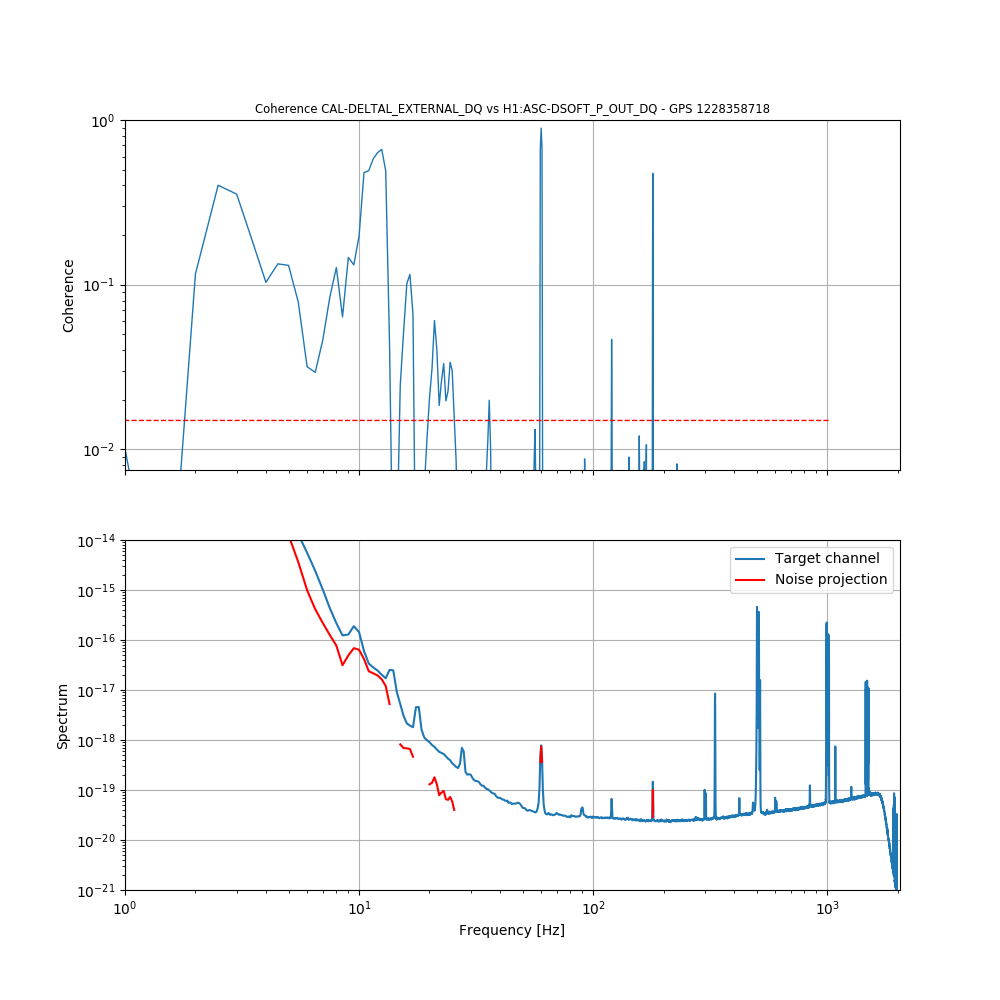
At around 6:00 UTC the range started to decline, it seems due to some noise in the form of a family of peaks below 40 Hz.

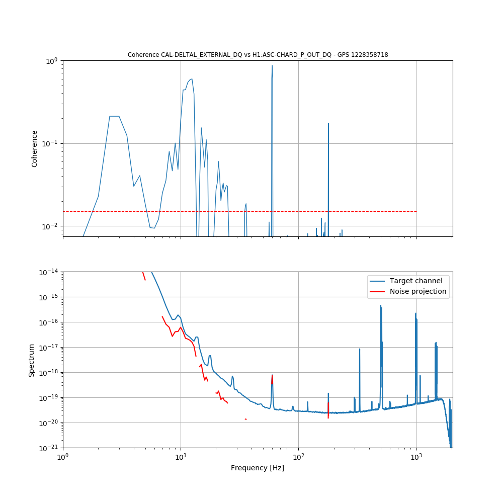
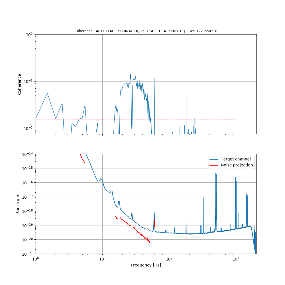
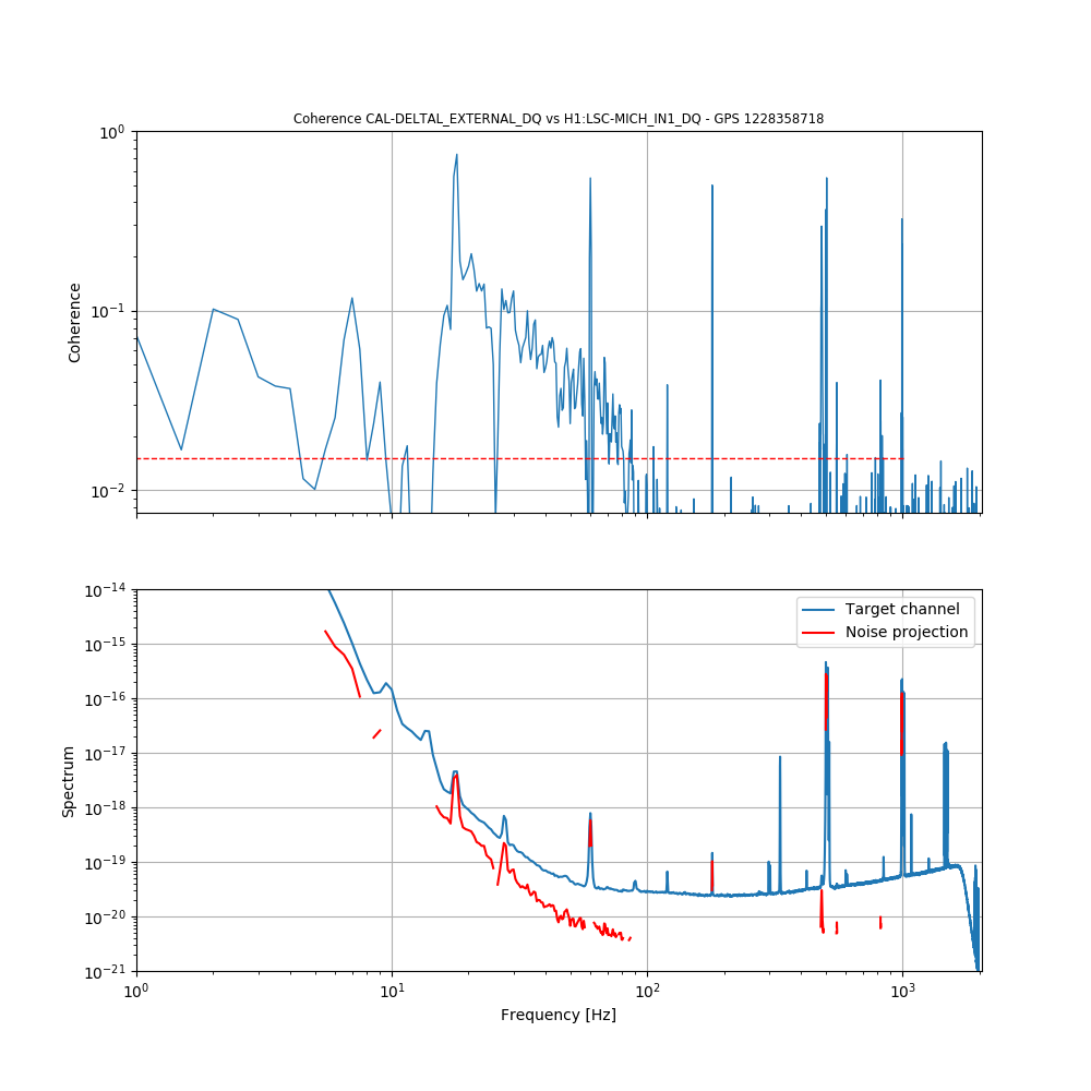
I ran two BruCo scans for a time before and after the change in noise.

Before: https://ldas-jobs.ligo.caltech.edu/~gabriele.vajente/bruco_lho_1228358718/

After: https://ldas-jobs.ligo.caltech.edu/~gabriele.vajente/bruco_lho_1228372218/

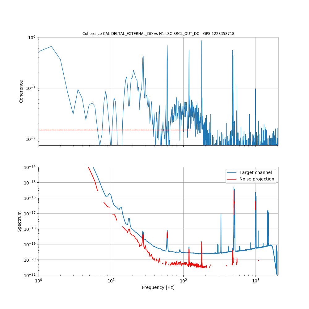
The most interesting thing I can see right now is that the peaks are coherent with the NULL stream.

Looking at coherences before the range worsening:

  • Low frequency (below 20 Hz) ASC (DSOFT_P and CHARD_P)
  • Between 15 and 40 Hz there is coherence with the centering loop DC4_P 
  • Coherence with MICH and SRCL is significant up to 200 Hz


Images attached to this comment
H1 SQZ
sheila.dwyer@LIGO.ORG - posted 23:30, Friday 07 December 2018 - last comment - 16:45, Monday 10 December 2018(45767)
squeezer injected into interferometer

Summary:

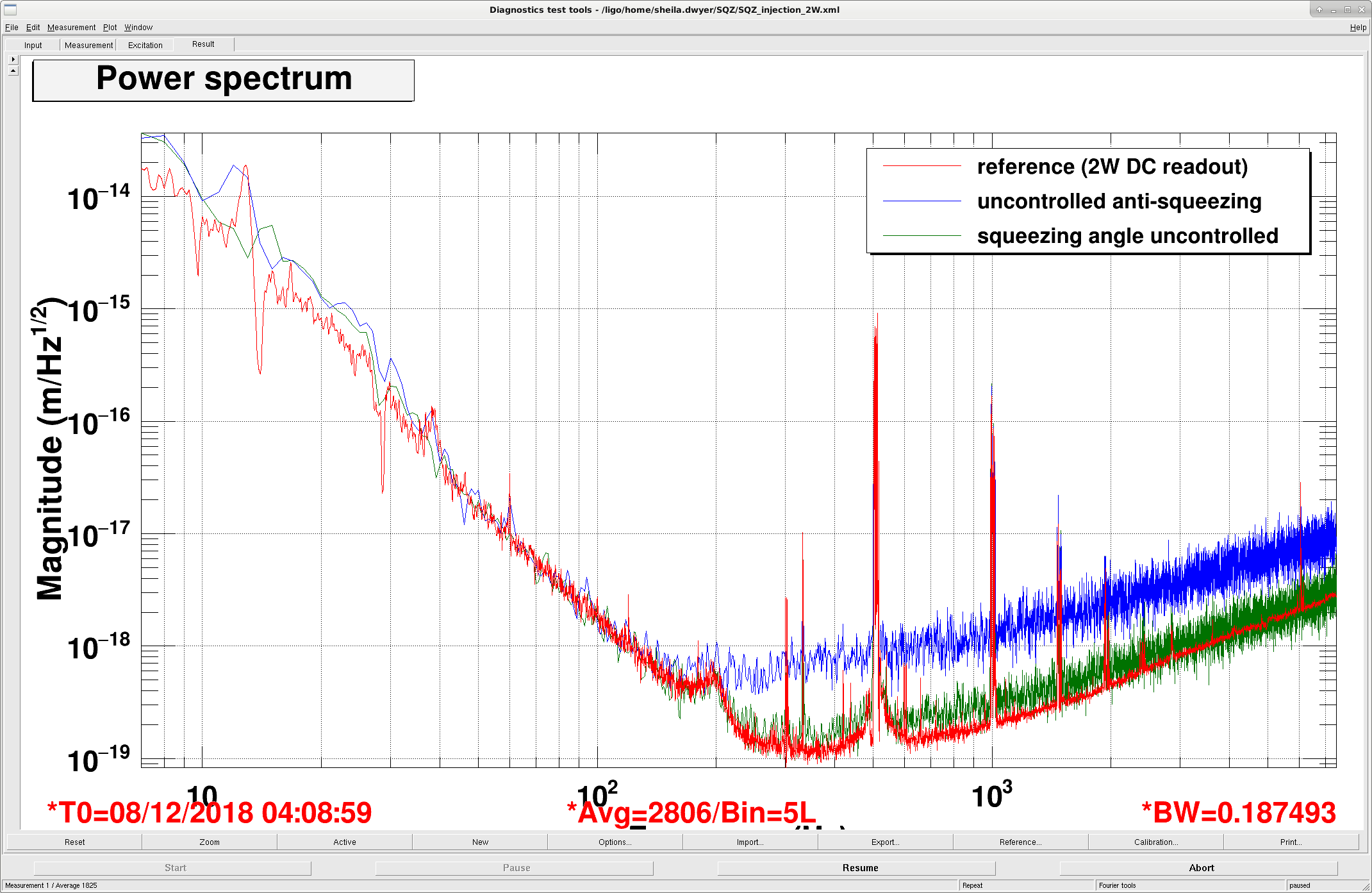
We were able to lock the squeezing angle using the 3MHz signal from the OMC DCPD's, and we have caused a few lockloses.  We have found that our locking scheme is introducing a lot of noise, so our next step is to lock the OPO length to the laser frequency.  

Locklosses:

In our first attempt we used the interferometer locked at 2W DC readout to look for the LO error signal.  We caused a lockloss then, and so we then changed to working with the interferometer locked on RF and the OMC locked.  We caused a couple of other locklosses this afternoon, one when the interferometer was locked on RF and the OPO became unlocked with the beam diverter open.  After this we added closing the beam diverter to the OPO guardian DOWN state, and the state CHECK_EOM (which we enter when the TTFSS EOM is railed).  

After successfully locking the squeezer angle, we transitioned to DC readout.  When we attempted to close the beam diverter we lost lock, which we also don't understand.  

We have been injecting ~10uW of CLF (measured on SQZT6), which gives us about 10 dBm of RF on the 3MHz demod.  We are wondering if this is too much and might be part of our lockloss problems.  We tried reducing it by a factor of 2.  

Locking:

Nutsinee will post details of the squeezing angle lock configuration that we used tonight, even though we don't plan to keep using this scheme. 

The basic steps:

Uncontrolled squeezing:

Images attached to this report
Non-image files attached to this report
Comments related to this report
daniel.sigg@LIGO.ORG - 11:39, Saturday 08 December 2018 (45772)

I am not sure what the free-running plot represents. In this case, the 2 lasers differ in frequency by as much as tens of kHz. This would completely invalidate the correlations that are responsible for squeezing. Every now and then the frequencies will cross and one might catch a short glimpse of (anti) squeezing.

The first plot is somewhat of a mystery too. If we really suffer from excess phase noise (as we have measured), why doesn't it effect squeezing at all frequencies? Could it be seeding through the CLF instead?

lisa.barsotti@LIGO.ORG - 14:26, Saturday 08 December 2018 (45776)

For reference, at LLO the nominal CLF power (measured on SQZT6) was 50 uW, tests up to 200 uW didn't show a large amount of seeding ( LLO log 41270). So, in principle 10 uW should be well below the seeding threshold.

On the other hand, some "seed hunting" on the double AOM path on ISCT6 was done before injection in the intererferometer, see for example: LLO log 37945 . I don't recall if you have done a similar characterization at LHO.

sheila.dwyer@LIGO.ORG - 11:20, Sunday 09 December 2018 (45784)

Lisa- no we haven't done any seed hunting here.  

Daniel- I agree that it isn't clear what is happening without the CLF injected, especially since the level of anti squeezing is way too high. 

daniel.sigg@LIGO.ORG - 20:40, Sunday 09 December 2018 (45790)

The 10µW is measured transmitted by the OPO, I believe the 50-200µW at L1 are incident to the OPO. The CLF LO signal is fairly high with ~6 dBm (in the quad phase) when we are locked.

lisa.barsotti@LIGO.ORG - 16:45, Monday 10 December 2018 (45826)

So, about the CLF power: all of the numbers reported in the LLO log so far quote the CLF power as measured on the CLF REFL diode, so BEFORE entering the OPO. The OPO has a 4% transmission for the 3 MHz - so indeed the 10 uW quoted for this LHO attempt, measured AFTER the OPO, are 5 times higher than the 50 uW used at LLO, since 50 uW * 0.04 = 2 uW of CLF AFTER the OPO. So, as we all discussed today, the first test would be to lower this power and see if the extra noise is caused by that.

LHO General
ryan.blair@LIGO.ORG - posted 11:34, Monday 19 November 2018 - last comment - 11:37, Monday 10 December 2018(45394)
Border router process crash resulted in brief Internet connectivity outage

Ryan, Carlos, Jonathan

At 18:56 UTC today, while following up on a note from LLO aLOG #41844 , one of the processes on the core router responsible for maintaining connectivity with our Internet providers encountered a segmentation fault. Carlos and Jonathan were called and they connected to the console to debug with me. The routing process was restarted and reconnected to our providers at 19:10 UTC. I believe this is directly related to the connectivity issues that Keith logged Friday night / Saturday morning and am checking for updates that may be related to the routing process crash issue.

Comments related to this report
ryan.blair@LIGO.ORG - 14:27, Monday 19 November 2018 (45407)

FRS #11860 filed.

ryan.blair@LIGO.ORG - 11:37, Monday 10 December 2018 (45814)

Likely related recurrence today around 19:25:40-08:00. System rebooted itself without intervention. This may be failing hardware; we have a cold standby available to swap in.

Displaying reports 44101-44120 of 88591.Go to page Start 2202 2203 2204 2205 2206 2207 2208 2209 2210 End