jeffrey.kissel@LIGO.ORG - posted 17:33, Wednesday 05 December 2018 (45726)
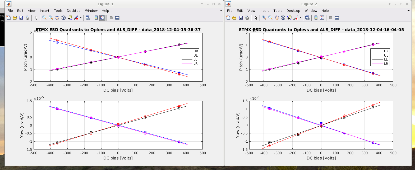
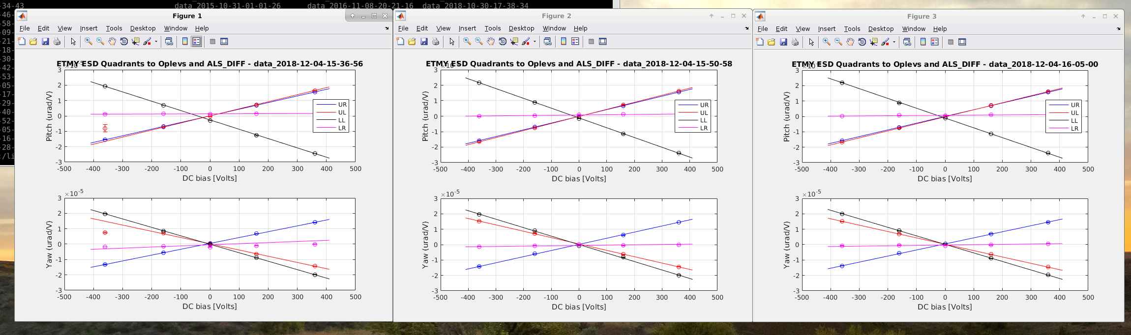
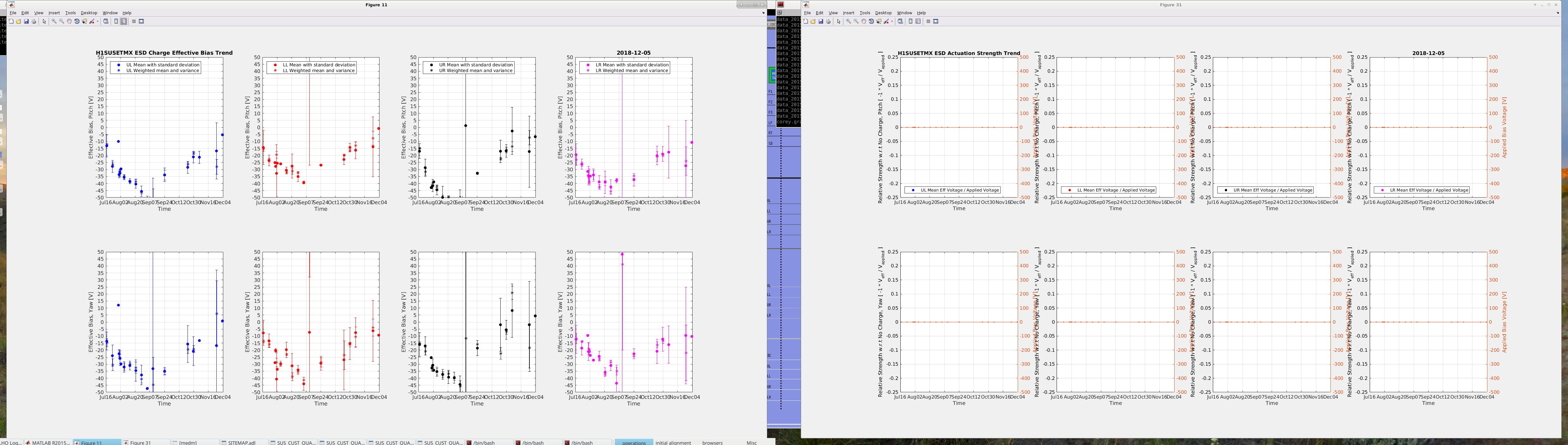
DARM OLG Model vs. Measurement -- A Reminder -- H1SUSETMX L3 / TST / ESD Actuation Strength droped by 2 Because We're Using 0.5 the ESD Bias Voltage
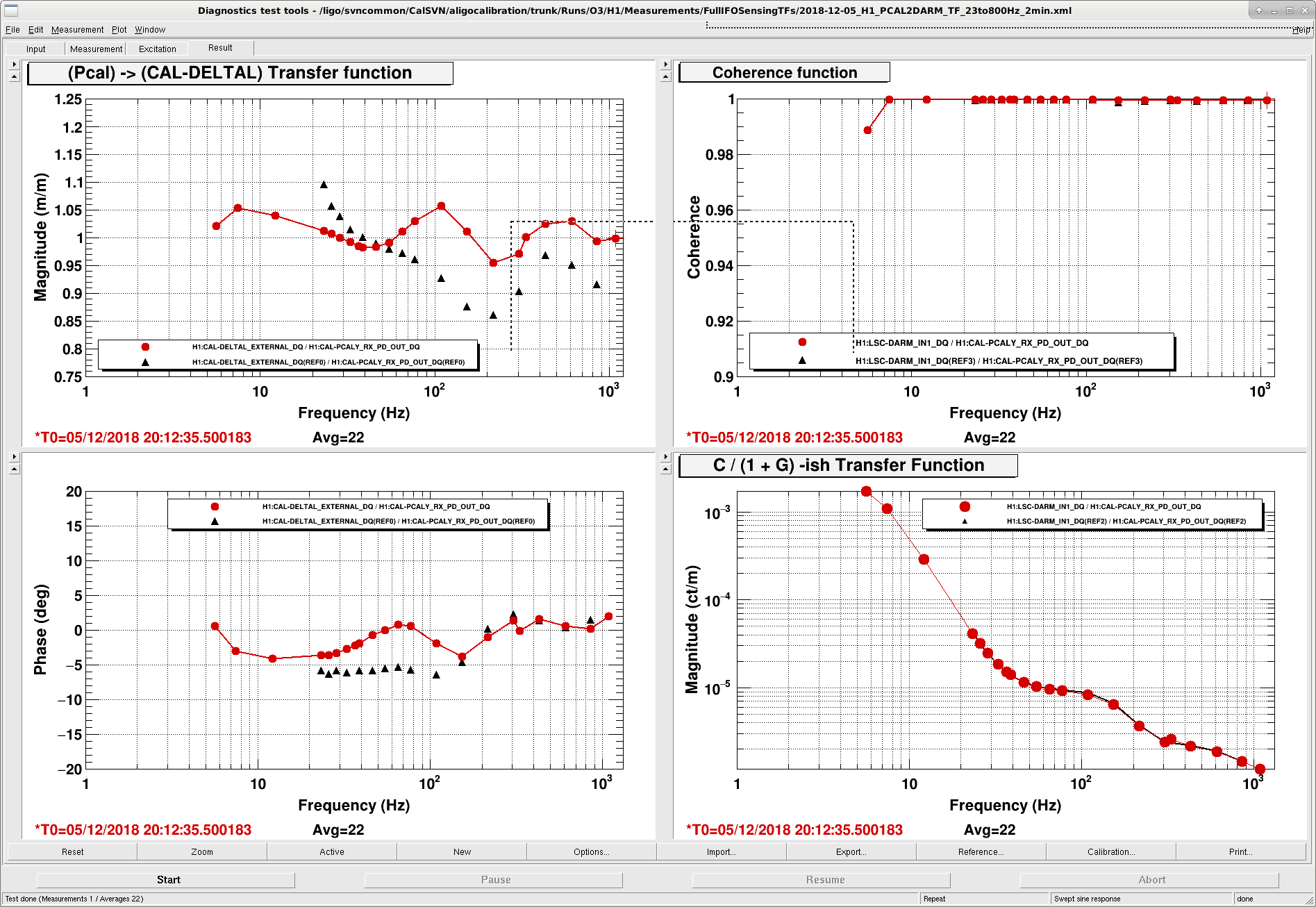
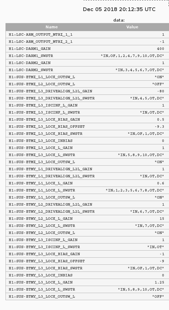
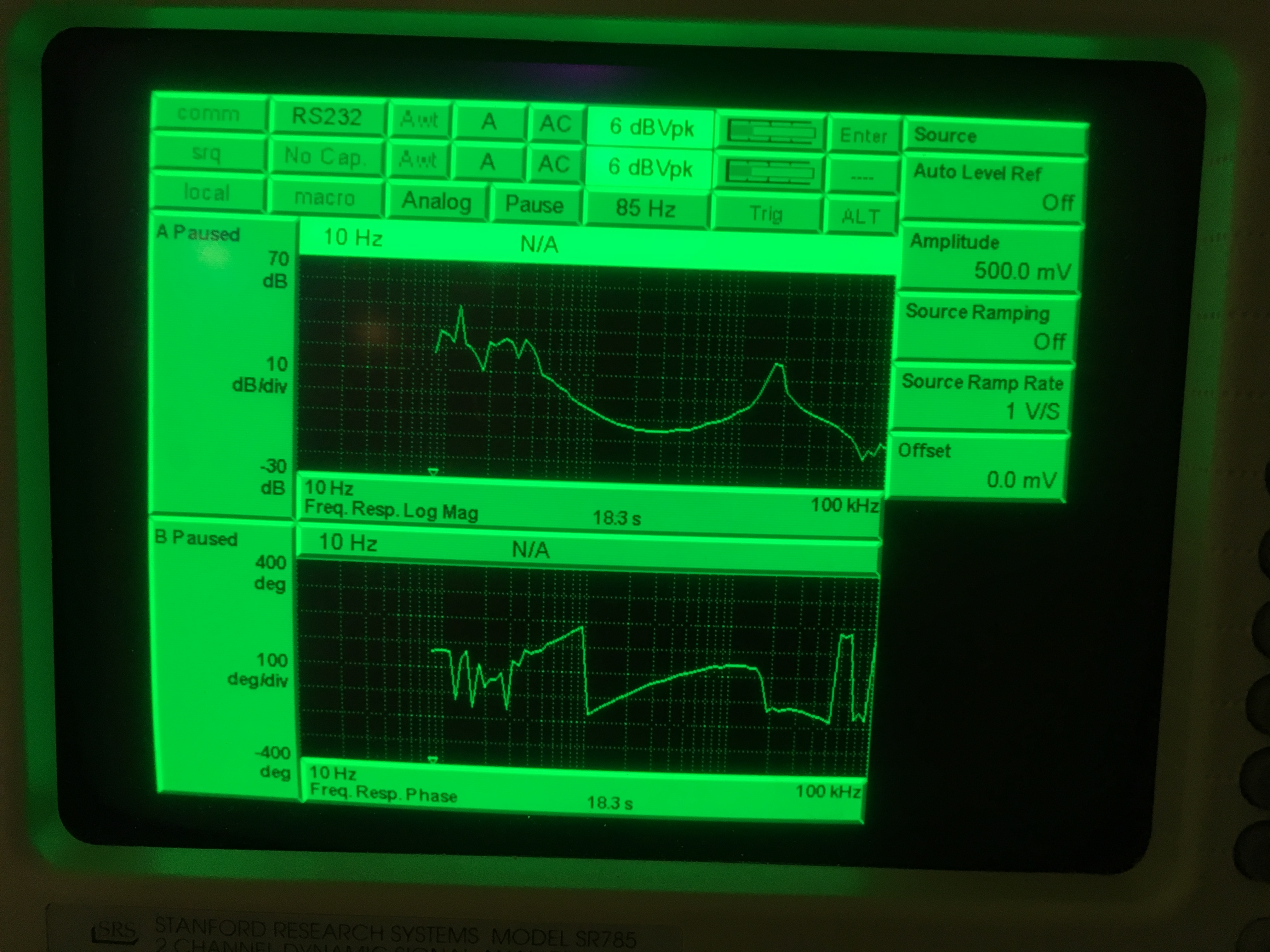
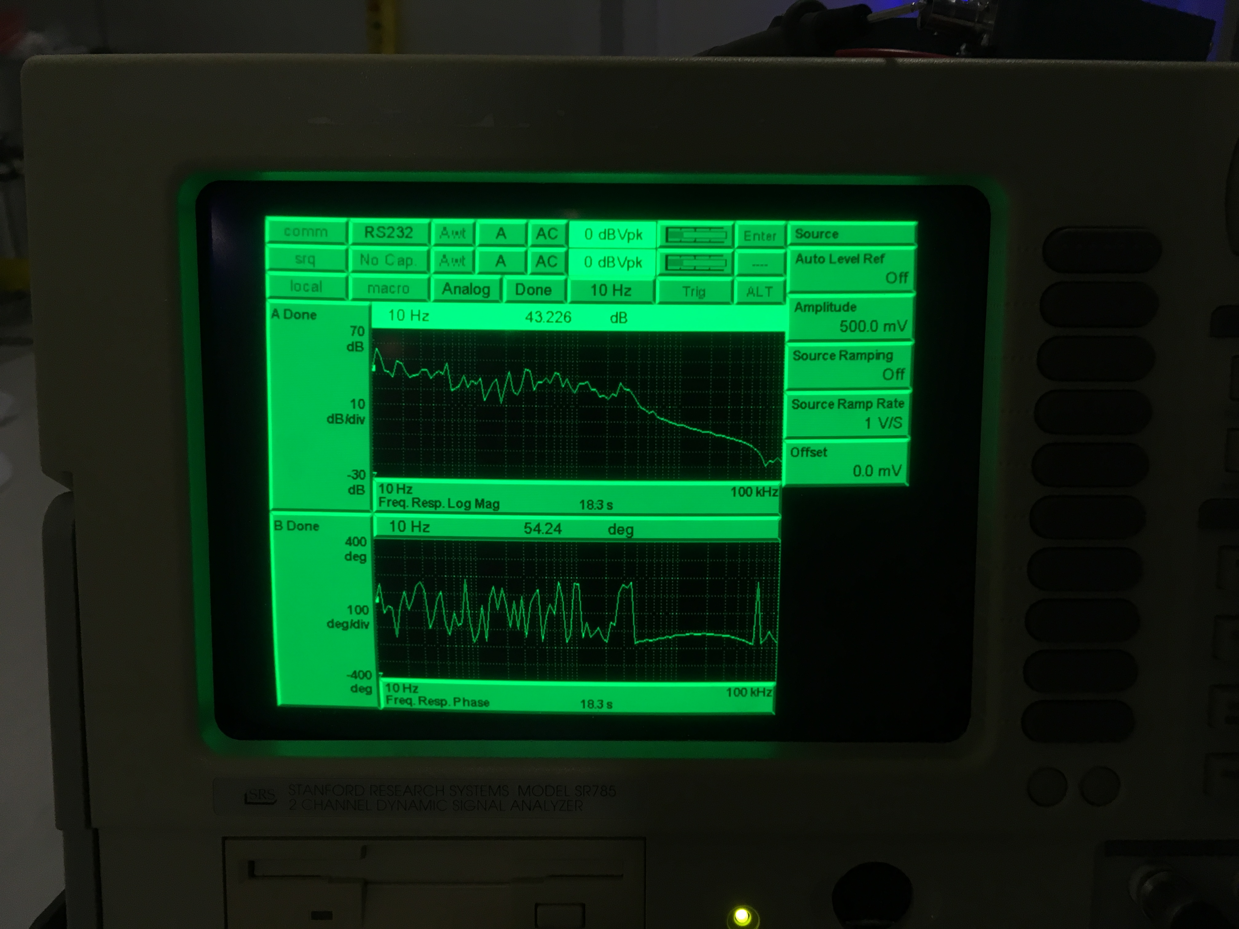
J. Kissel

While updating the DARM loop model, in order to compare with the measured loop (from LHO aLOG 45714), I found two things:
    (1) That the ETMX_L3_DRIVEALIGN_L2L gain had changed from -40 to -80, and
    (2) That the loop model was over estimating the measured DARM OLG TF  by a factor of two.

This lead me down a small rabbit hole, in which I found Peter Fritschel's brief entry from early in November (LHO aLOG 45193), which states that "we've reduced the ETMX bias voltage from -430 V_ESD (/40 = 10.75 V_DAC) to -218 V_ESD (/40 = 5.45 V_DAC)".
However, this was permanent change implemented in guardian / the ETMX bias path in a sneaky way:
    (a) the H1:SUS-ETMX_L3_LOCK_INBIAS is now zero (the bias record was moved from INBIAS to the BIAS_OFFSET so we can use the ramping of the OFFSET)
    (b) the H1:SUS-ETMX_L3_LOCK_BIAS_OFFSET is -9.3 (V_DAC * 40 V/V = 372 V_ESD), and
    (c) the H1:SUS-ETMX_L3_LOCK_BIAS_GAIN is 0.5
    (d) the ETMX_L3_DRIVEALIGN_L2L gain is -80 (where it used to be 40)
such that the output is (including the cnts2V filter gain of 2^18 / 20 = 13107.2) = -60948.5 18-bit DAC counts = -4.65 V_DAC = 186 V_ESD.
Remember also --
    (e) we compensate the fact that we have a 20 bit DAC by dividing the requested DAC counts by 4 in the ESDOUTF banks.

#TangledWebsWoven.

Before I figured out the mystery, however, I was allowed some time to measure the actuation strength of the L3 stage with the PCAL system (we need this for ER13 anyways) to help me. See the 1st and 2nd attached results. They report that the actuation strength is now 2.149e-11 N/V^2, or 2.294e-12 N/ct_18bitDAC, which is half the value measured in October (LHO aLOG 44690), before we switched to a 20 bit DAC (which doesn't affect the estimate because of (e)), and before the above sneaky bias voltage reduction (a-d).

The problem for the calibration group to fix: yet again we've been out-smarted by the ISC team in its infinite ways of setting a  single number.
The DARM loop model does not yet include (c), and because of (e) we haven't yet updated the model DAC gain from an 18 to 20 bit DAC gain thinking we could get away with ignoring it after the ESDOUTF compensation.
So -- I can make the DARM loop model work by
     (i) accurately changing the ETMX_L3_DRIVEALIGN_L2L gain at -80
     (ii) leaving the model DAC gain at 2^18/20 V
     (iii) incorrectly leaving the bias voltage at -9.3 V_DAC (= 372 V_ESD)
     (iv) reducing the physical actuation strength of the ESD by a factor of 2 from 4.1303e-11 to 2.149e-11 N/V^2

3rd attached result is this DARM Open Loop Gain model vs. measurement.

L3 / TST Actuation Function Measurements:
/ligo/svncommon/CalSVN/aligocalibration/trunk/Runs/O3/H1/MeasurementsFullIFOActuationTFs/
    2018-12-05_H1SUSETMX_L3_PCAL2DARM_5min.xml
    2018-12-05_H1SUSETMX_L3_iEXC2DARM_5min.xml

Data Processing scripts that makes the attached plots:
/ligo/svncommon/CalSVN/aligocalibration/trunk/Runs/O3/H1/Scripts$
    DARMOLGTFs/process_darmolg_20181205.py
    FullIFOActuationTFs/process_actuationmeas_20181205.py
    FullIFOSensingTFs/process_sensingmeas_20181205.py

New DARM loop Model that informs the attached final 3rd plot:
/ligo/svncommon/CalSVN/aligocalibration/trunk/Runs/O3/H1/params
    modelparams_H1_20181205.py
Non-image files attached to this report