Ops Shift Log: 11/28/2018, Day Shift 16:00 – 00:00 (08:00 - 16:00) Time - UTC (PT)
State of H1: Unlocked for post vent commissioning
Intent Bit: Commissioning
Support: N/A
Incoming Operator: N/A
Shift Summary: Vent recovery and commissioning
Activity Log: Time - UTC (PT)
15:10 (06:10) Peter – Into the PSL enclosure
16:00 (08:00) Start of Shift
16:07 (08:07) Karen – Going into the LVEA for morning cleaning
16:21 (08:21) Peter – Out of the PSL enclosure
16:56 (08:56) Chris – Moving scaffolding from LVEA into the High Bay via roll-up door
16:57 (08:57) Nutsinee – Going to HAM6 area
16:59 (08:59) Vanessa – Going into LVEA for cleaning
17:19 (09:19) Karen – Going to End-Y for cleaning (Set SEI_CONF to WINDY_NO_BRSY)
17:44 (09:44) Vanessa – Going to End-X for cleaning (Set SEI_CONF to VERY_WINDY_NOBRSXY)
17:50 (09:50) Karen – Finished at End-Y – Going to Mid-Y
18:01 (10:01) Richard – Going into the CER
18:08 (10:08) Karen – Finished at Mid-Y
18:17 (10:17) Vanessa – Finished at End-X (Set SEI_CONF back to WINDY)
18:33 (10:33) Kyle – Going into the LVEA to check the various pump-down vacuum pumps
18:40 (10:40) Kyle – Out of the LVEA
18:49 (10:49) Gerardo – Going into the LVEA to check the new NAG pumps
18:58 (10:58) Gerardo – Out of the LVEA
19:00 (11:00) Chris – Out of the LVEA
19:27 (11:27) Patrick & Gerardo – De-Gassing NEG-1
19:34 (11:34) Gerardo & Patrick – Finished trying to de-gas NEG-1
19:46 (11:46) Jenne & Nutsinee – Going to ICS racks near the PSL
20:08 (12:08) Jenne & Nutsinee – Out of the LVEA
20:11 (12:11) Richard & Jenne – Going to ICS racks to do some cabling work
20:22 (12:22) Jenne & Richard – Out of the LVEA
21:15 (13:15) Kyle & Gerardo – Going to Mid-Y
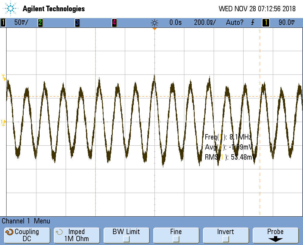
21:30 (13:30) Peter – Going into the LVEA to make a measurement
21:40 (13:40) Peter – Out of the LVEA
23:21 (15:21) Nutsinee – Into LVEA to Squeezer table
00:00 (16:00) End of Shift