Daniel Brown, Cheryl Vorvick, Haocun Yu, Terry McRae, Georgia Mansell
Summary: Today we started recovering the corner IFO after the vent. We worked on IMC/IO revival, alignment, and squeezer alignment. The IMC recovered well and we have reasonable transmission and reflection levels.
We are currently having a guardian/front end problem when locking PRMI - The ISC_DRMI guardian tries to turn on H1:LSC-MICH1_FM2 when it reaches the PRMI_LOCKED state. This filter module has a yellow "LC" flag above it on the MEDM screen (does this mean it is under local control?), and toggling the button or trying to set it in a guardian shell does not work. We're not sure how to get around this. First attachment is the guardian log when trying to toggle FM2.
While PRMI acquires easily we're having trouble locking DRMI (a familiar situation with short locks but nothing that holds well).
General vent recovery
- I transitioned the LVEA to laser hazard
- Turned on the HAM6 PZT HV and fast shutter HV
- Turned on the fast shutter chassis (in the rack next to isct6), and enabled its high voltage
- note HAM6 HEPI is locked, so we left its guardian paused, in the READY state, and the SEI_HAM6 guardian in ISI_DAMPED_HEPI_OFFLINE
- We've set the gate_valve_flag parameter in lscparams to True, so we can do DRMI without arms
IMC revival
- We locked the IMC at 2 W, it was clearly misaligned in yaw to start off with. We adjusted MC2 so we could lock on the 00 mode nad used the WFS to fix the alignment
- Note to self, to get the WFS going from a pretty rubbish first alignment we had to lower the trigger threshold (from 40 to 21), then increase the IMC WFS gain by hand from 0.04 to 0.4. We waited for the WFS to converge then offloaded them with the IMC_LOCK guardian.
- The reflected power of the IMC is at 8.3 mW [edit: this was a typo, it's at 0.083 mW with ~1.9W input power], reduced again after two-tuesdays-ago's mystery excursion.
- Cheryl ran the IMC-spot-position measuring script. She tried to restore the IMC mirrors to their positions back in August, using the witness sensors, but found this was not a good alignment. She later found a good alignment.
Corner station alignment
- We mostly got through initial alignment with the ALIGN_IFO guardian without too many problems, we couldn't do input align without the arms locked though
- We first did MICH_DARK and MICH_BRIGHT to check the contrast defect with the new TCS settings. Initially we measured ~1% contrast defect, however after we tweaked up the input alignment this was reduced to ~0.65%.
- To adjust the input alignment we went to the PRC_ALIGN state of ALIGN_IFO and adjusted IM4 and PR2 by hand to increase LSC_POP_A_LF. The input alignment might not be optimal yet.
Squeezer work
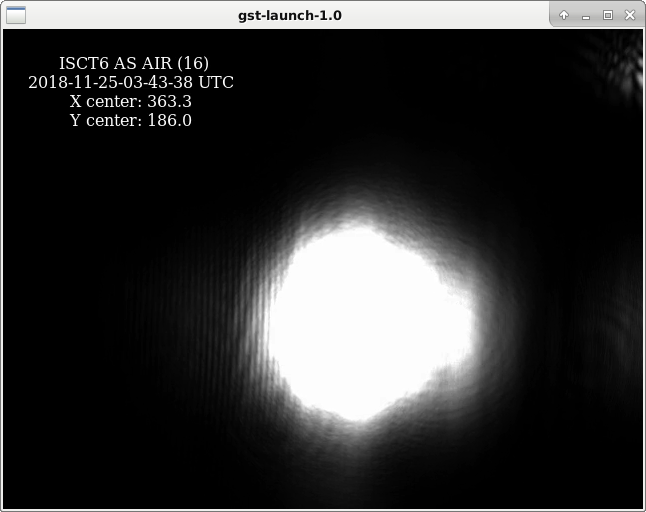
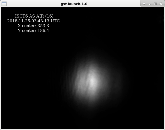
We repeated the squeezer single-bounce tests reported in alog 45375, with more seed power. We have ~20 counts on AS_A and AS_B when bouncing the seed beam off the SRM, compared with 8 counts 1 week ago. We still didn't have enough power to see the squeezer beam reflected off ITMX when SRM is misaligned. The second attachment shows the squeezer seed beam, as reflected off SRM, visible on the AS_AIR camera on ISCT6. Qualitatively, it does not look obviously astigmatic.