Daniel Brown, Cheryl Vorvick, Haocun Yu, Terry McRae, Georgia Mansell
Summary: Today we started recovering the corner IFO after the vent. We worked on IMC/IO revival, alignment, and squeezer alignment. The IMC recovered well and we have reasonable transmission and reflection levels.
We are currently having a guardian/front end problem when locking PRMI - The ISC_DRMI guardian tries to turn on H1:LSC-MICH1_FM2 when it reaches the PRMI_LOCKED state. This filter module has a yellow "LC" flag above it on the MEDM screen (does this mean it is under local control?), and toggling the button or trying to set it in a guardian shell does not work. We're not sure how to get around this. First attachment is the guardian log when trying to toggle FM2.
While PRMI acquires easily we're having trouble locking DRMI (a familiar situation with short locks but nothing that holds well).
General vent recovery
- I transitioned the LVEA to laser hazard
- Turned on the HAM6 PZT HV and fast shutter HV
- Turned on the fast shutter chassis (in the rack next to isct6), and enabled its high voltage
- note HAM6 HEPI is locked, so we left its guardian paused, in the READY state, and the SEI_HAM6 guardian in ISI_DAMPED_HEPI_OFFLINE
- We've set the gate_valve_flag parameter in lscparams to True, so we can do DRMI without arms
IMC revival
- We locked the IMC at 2 W, it was clearly misaligned in yaw to start off with. We adjusted MC2 so we could lock on the 00 mode nad used the WFS to fix the alignment
- Note to self, to get the WFS going from a pretty rubbish first alignment we had to lower the trigger threshold (from 40 to 21), then increase the IMC WFS gain by hand from 0.04 to 0.4. We waited for the WFS to converge then offloaded them with the IMC_LOCK guardian.
- The reflected power of the IMC is at 8.3 mW [edit: this was a typo, it's at 0.083 mW with ~1.9W input power], reduced again after two-tuesdays-ago's mystery excursion.
- Cheryl ran the IMC-spot-position measuring script. She tried to restore the IMC mirrors to their positions back in August, using the witness sensors, but found this was not a good alignment. She later found a good alignment.
Corner station alignment
- We mostly got through initial alignment with the ALIGN_IFO guardian without too many problems, we couldn't do input align without the arms locked though
- We first did MICH_DARK and MICH_BRIGHT to check the contrast defect with the new TCS settings. Initially we measured ~1% contrast defect, however after we tweaked up the input alignment this was reduced to ~0.65%.
- To adjust the input alignment we went to the PRC_ALIGN state of ALIGN_IFO and adjusted IM4 and PR2 by hand to increase LSC_POP_A_LF. The input alignment might not be optimal yet.
Squeezer work
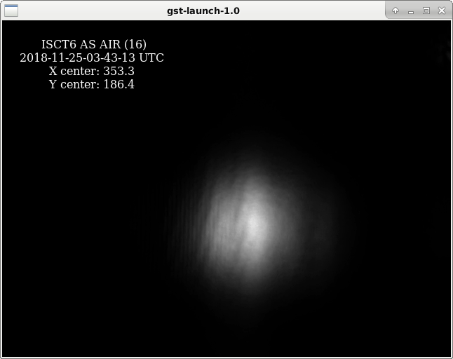
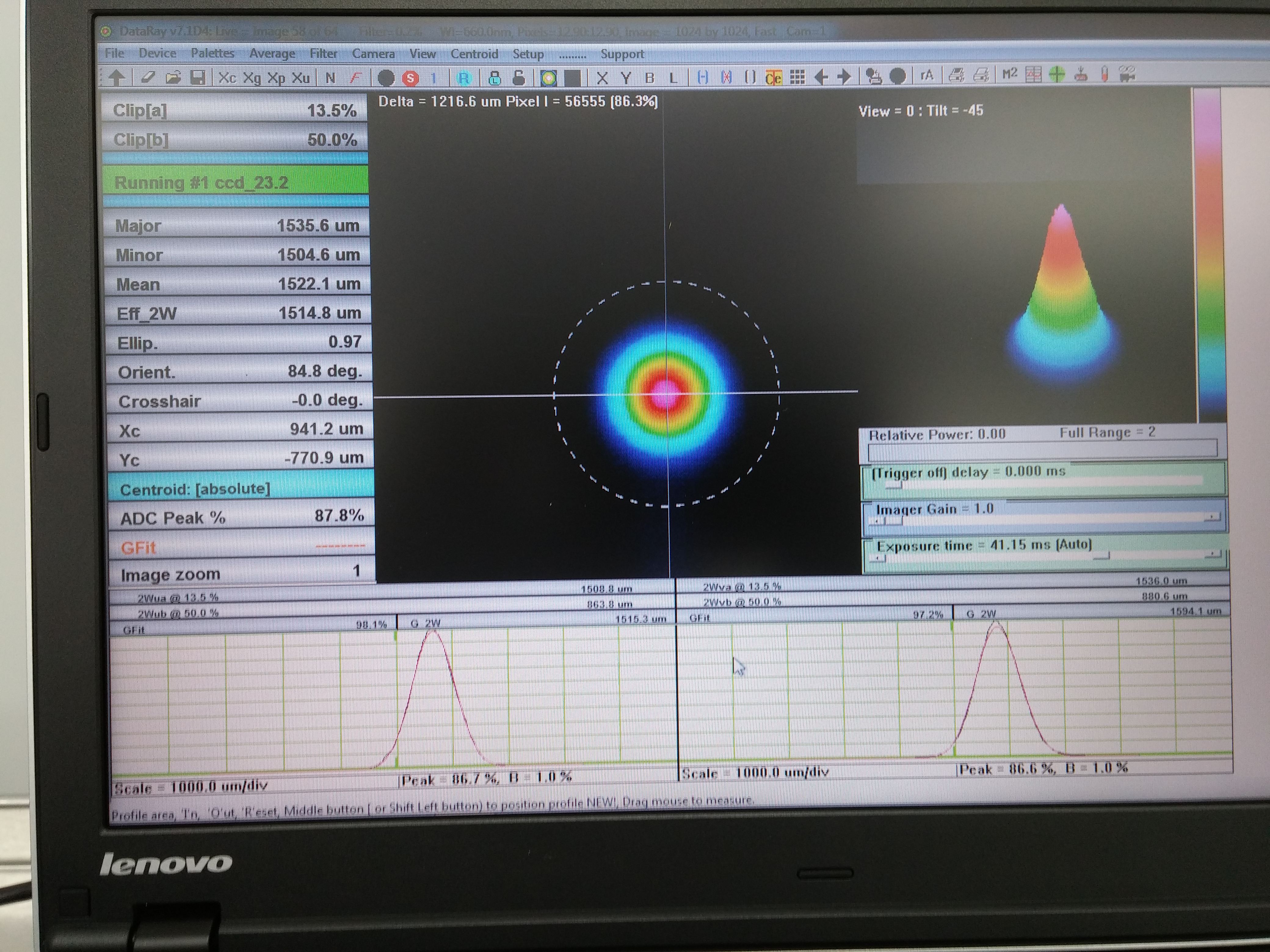
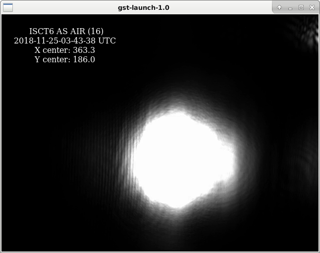
We repeated the squeezer single-bounce tests reported in alog 45375, with more seed power. We have ~20 counts on AS_A and AS_B when bouncing the seed beam off the SRM, compared with 8 counts 1 week ago. We still didn't have enough power to see the squeezer beam reflected off ITMX when SRM is misaligned. The second attachment shows the squeezer seed beam, as reflected off SRM, visible on the AS_AIR camera on ISCT6. Qualitatively, it does not look obviously astigmatic.
Daniel Brown, Thomas Vo, Georgia Mansell
*actual channels I'm quoting are POPAIR_B_RF[18/90]_I_NORM_MON
Images of AS AIR on DRMI lock today with the current 50W pretunings.
We also began tuning CO2 differentially to see how the sideband build up on the OSA changes. The OSA scan attached is after the first step of 100mW change. Another 100mW change was applied but we lost DRMI and then the PSL went down.
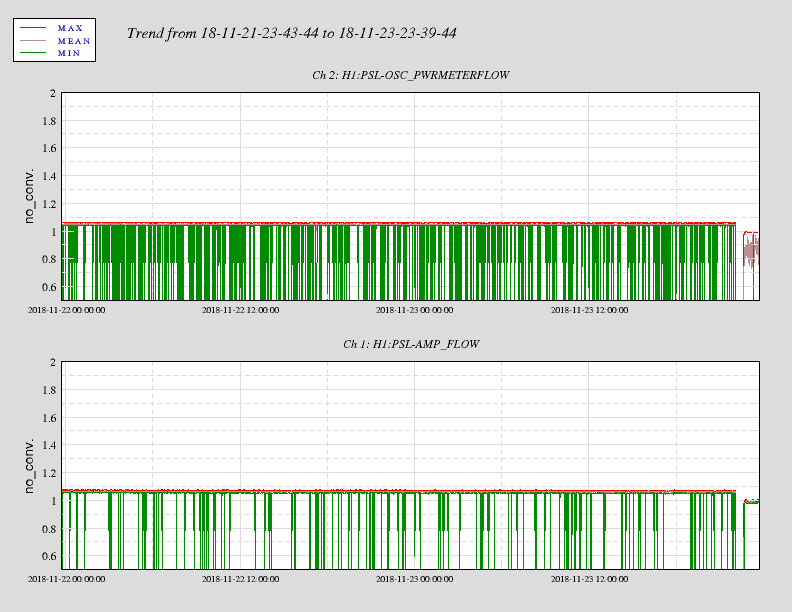
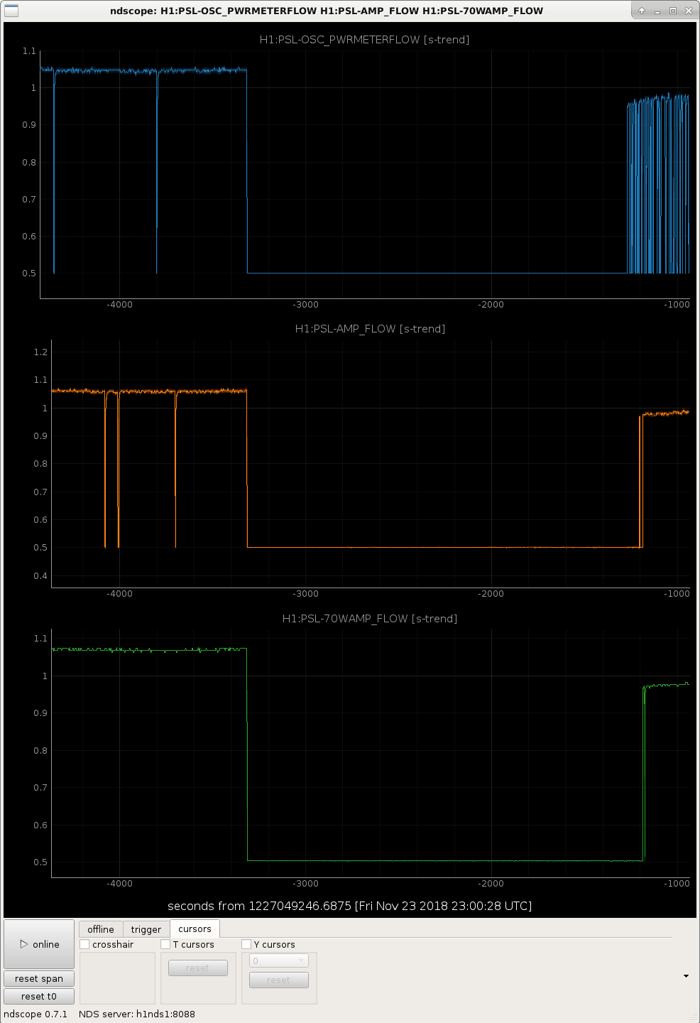
Attached is the trend data plot for the flow rates in the power meter circuit, the front end laser, and the 70 W amplifier.
Lots of glitches, not sure of the reason why. Especially when compared to the 70 W amplifier cooling circuit.
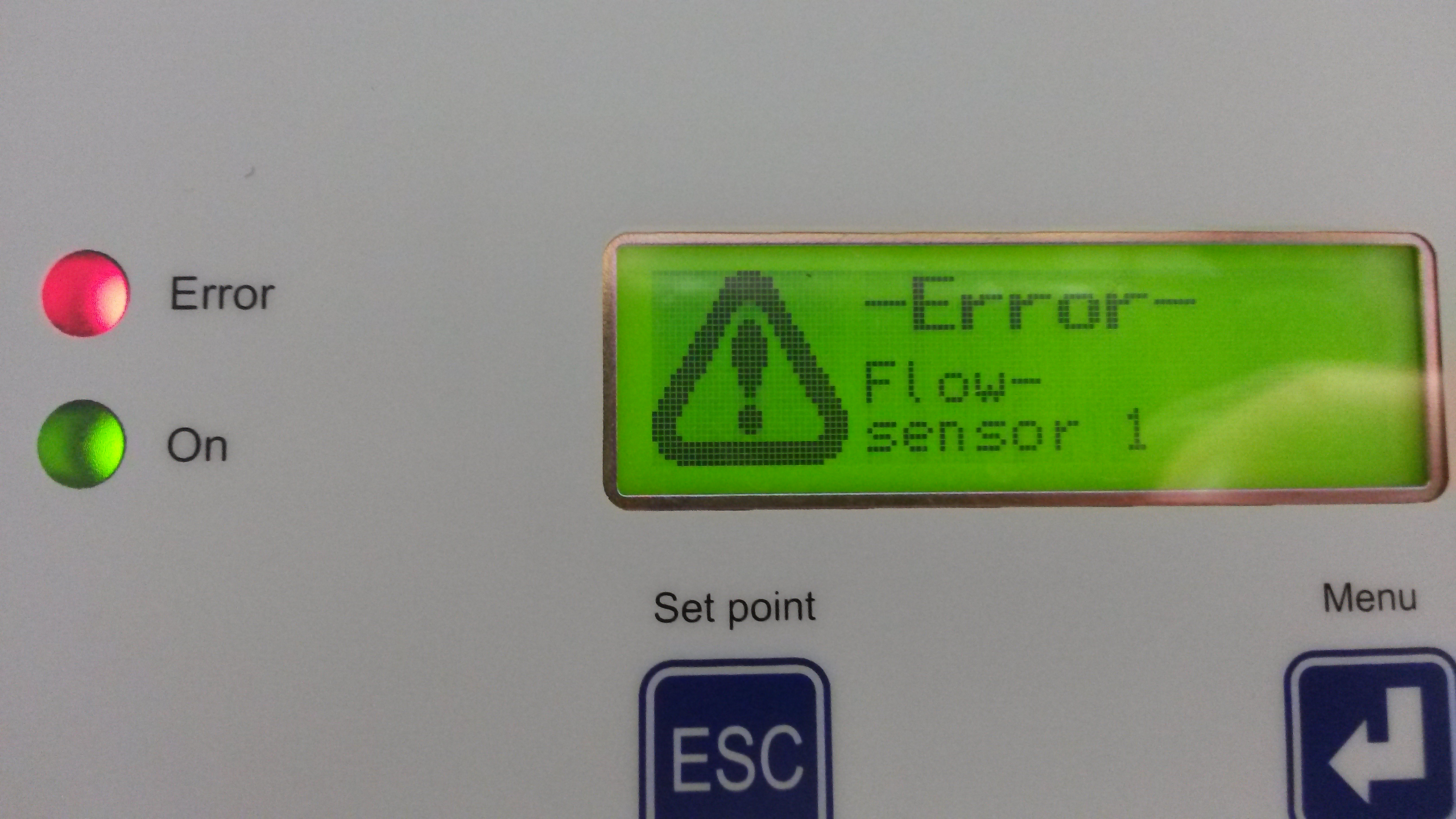
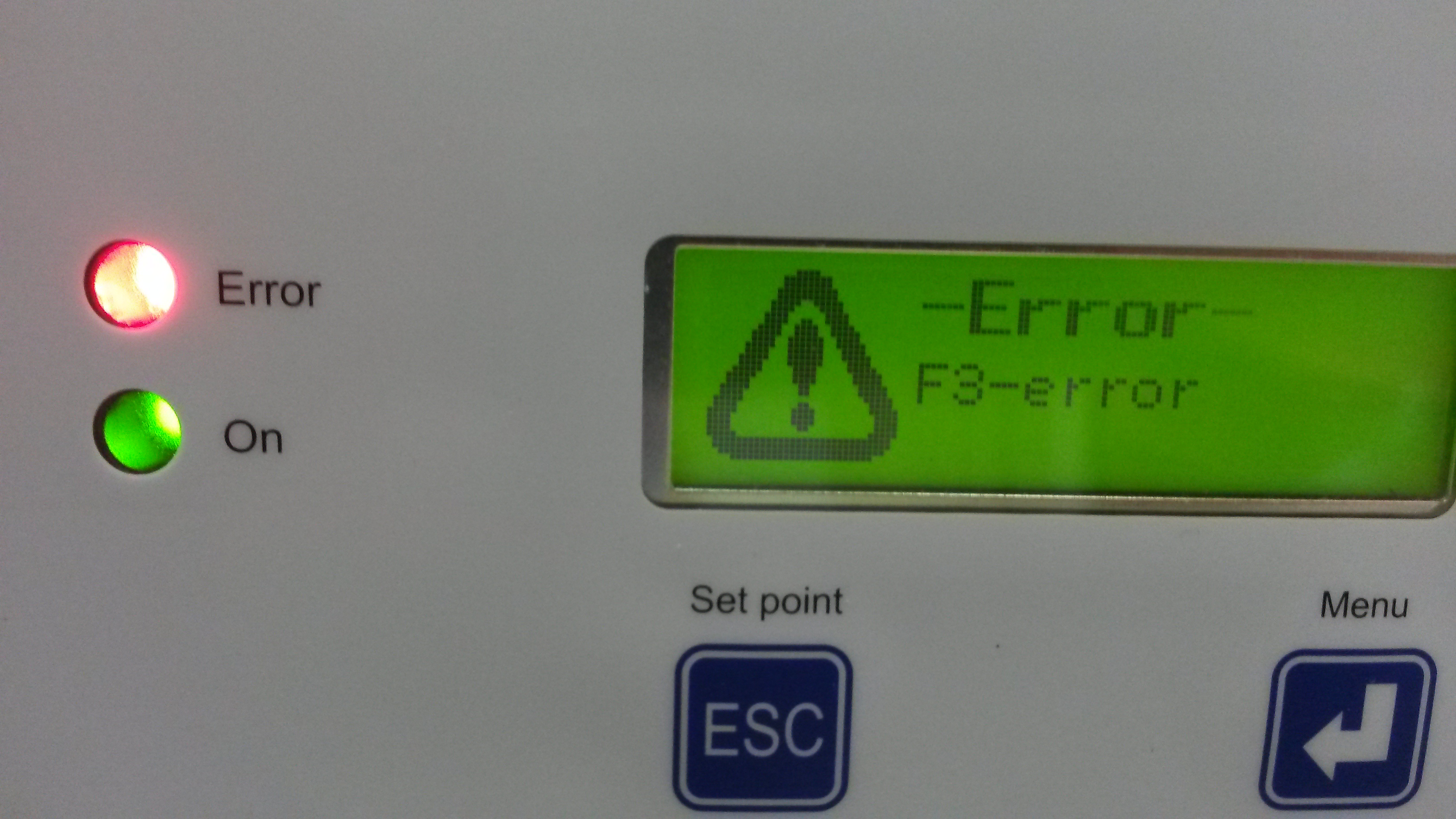
The diode chiller is indicating an error message of "F3-error", which is something related to the hot gas valve. That
might be an indication that the diode chiller needs servicing, I don't know. The diode chiller temperature over the same
period of time looks pretty constant at 20 +/- 0.2 degC. The diode chiller flow looks pretty constant over the same time
interval as well.
The flow rate from the crystal chiller is noticeably lower upon restart. 14 lpm cf. 15.7 lpm.
After restarting the laser, the power meter flow somewhat regularly flashes red indicating that the flow rate has
dropped to 0.5 lpm or lower.
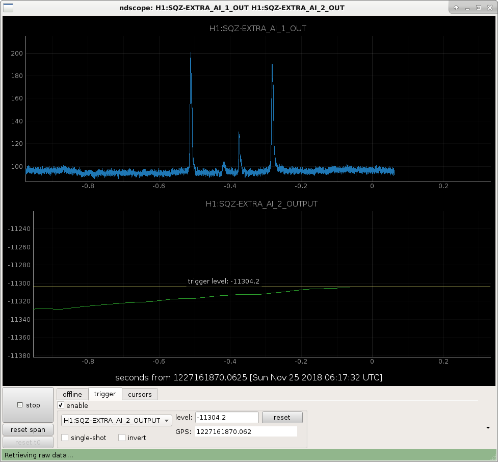
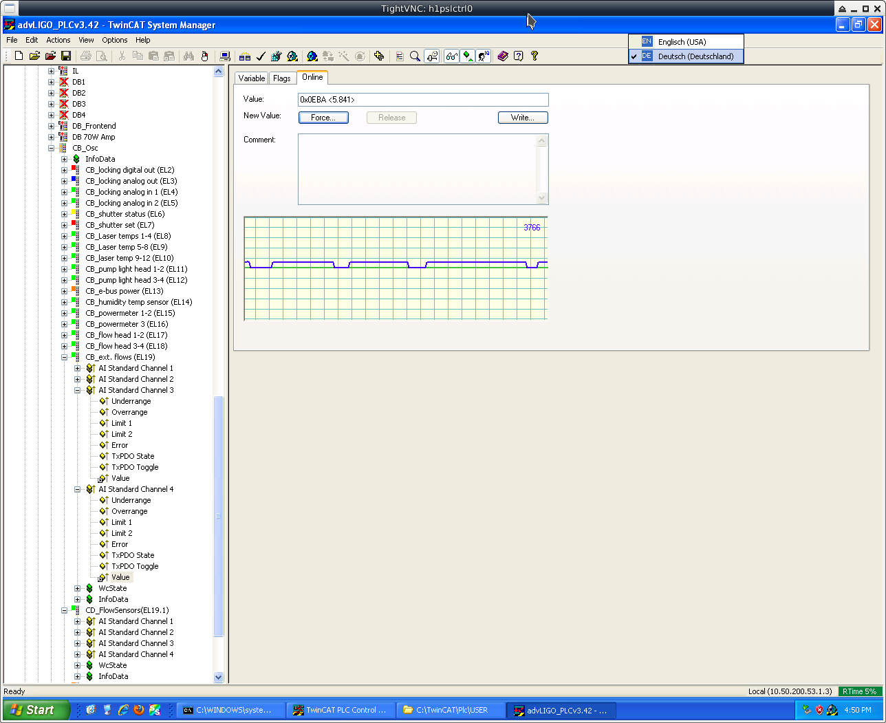
Attached is the data dump from TwinCAT. In some stretches one can see some ripples before the flow rate
drops to zero. These small fluctuations might be air bubbles making their way through the system. The
drop outs occur with enough regularity that we ought to be able to test whether it's the EL3054 analogue
input terminal being intermittent or if it really is a flow rate problem.
The alternate is that perhaps the connections in the junction box might be loose, although unlikely
I would think.
Squeezer recovery work after pumping down:
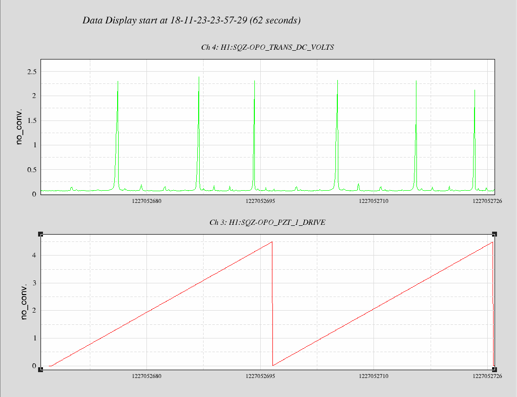
A quick cavity scan with green beam, as attached below.
Calculation:
This is pretty much better than before, and consistent with the scan in-air.
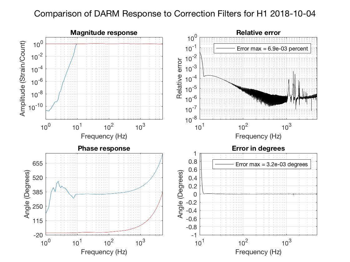
I've produced new filters for use in the GDS calibration pipeline with improvements to the high-pass filters. These filters are otherwise the same as those mentioned in LHO aLOG 45428. The new filters can be found in the calibration SVN at:
aligocalibration/trunk/Runs/PreER13/GDSFilters/H1GDS_1227048227.npz
They were produced from SVN revision 6059 with these parameters files:
The changes made in the high-pass filters were:
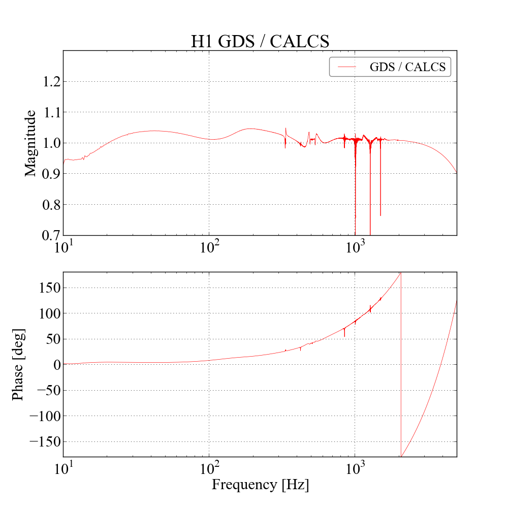
The first three of the attached plots show comparisons of the time-domain filters to the frequency-domain models. The 4th plot shows ASDs produced by GDS using this filter and by CALCS. The last plot is a transfer function beteen CALCS and GDS.
The primary and redundant GDS calibration pipelines were restated around GPS 1227050381 to pick up these new filters.
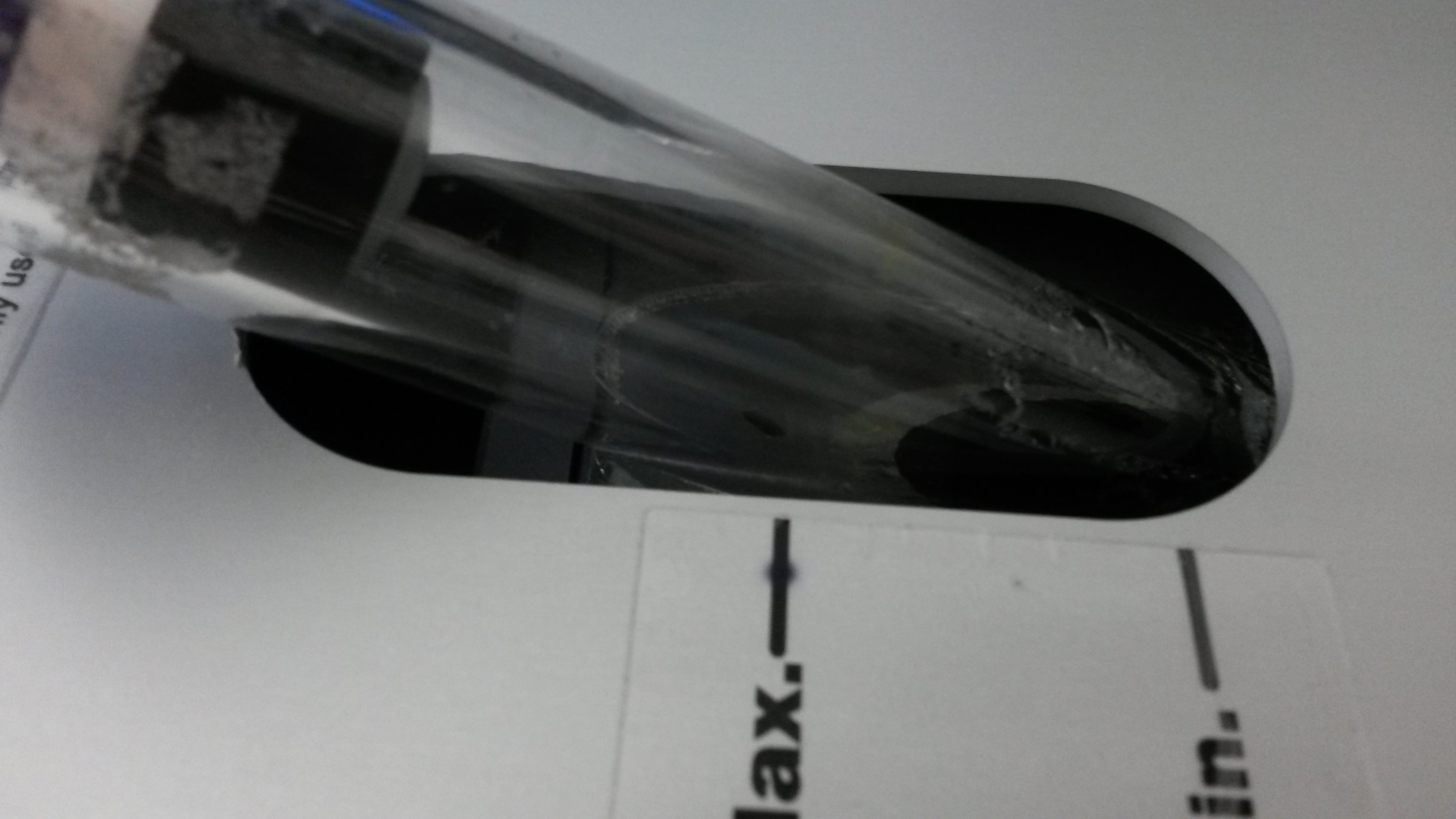
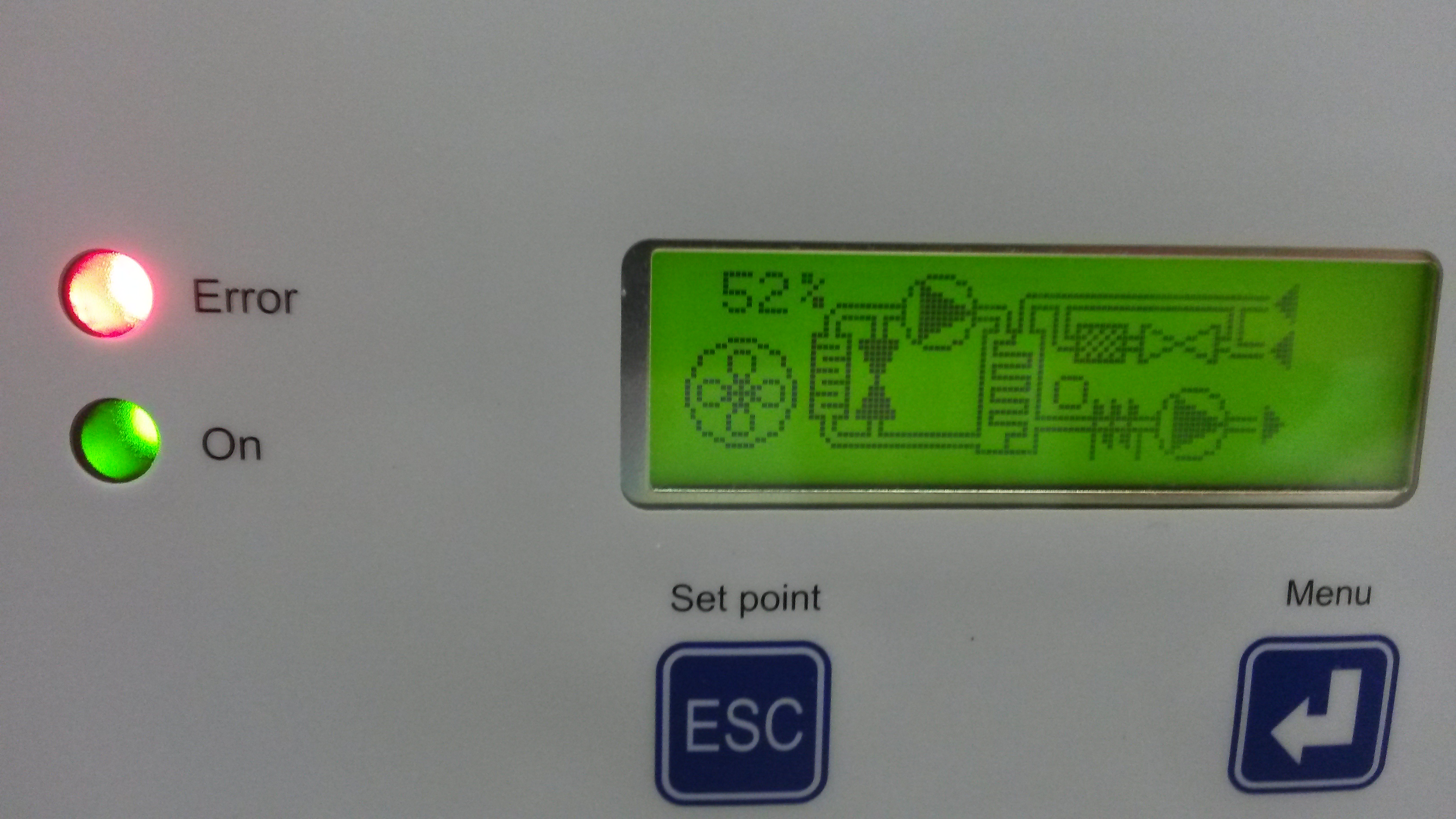
Pictures from the PSL chillers: first two are the top chiller "Wallace," last two are from the lower chiller. Jason was called, Danny and Georgia are here waiting for PeterK, who is on his way in.
Jason (remote), Peter (remote), Cheryl, Georgia, Daniel
The PSL switched itself off today around 22:00 UTC. The crystal chiller had run out of water. We topped this back up and got the chiller restarted. However the various flow meters are all reading slightly low now. The power meter flow sensor seems to be glitching a lot. Peter is on his way in to check things out.
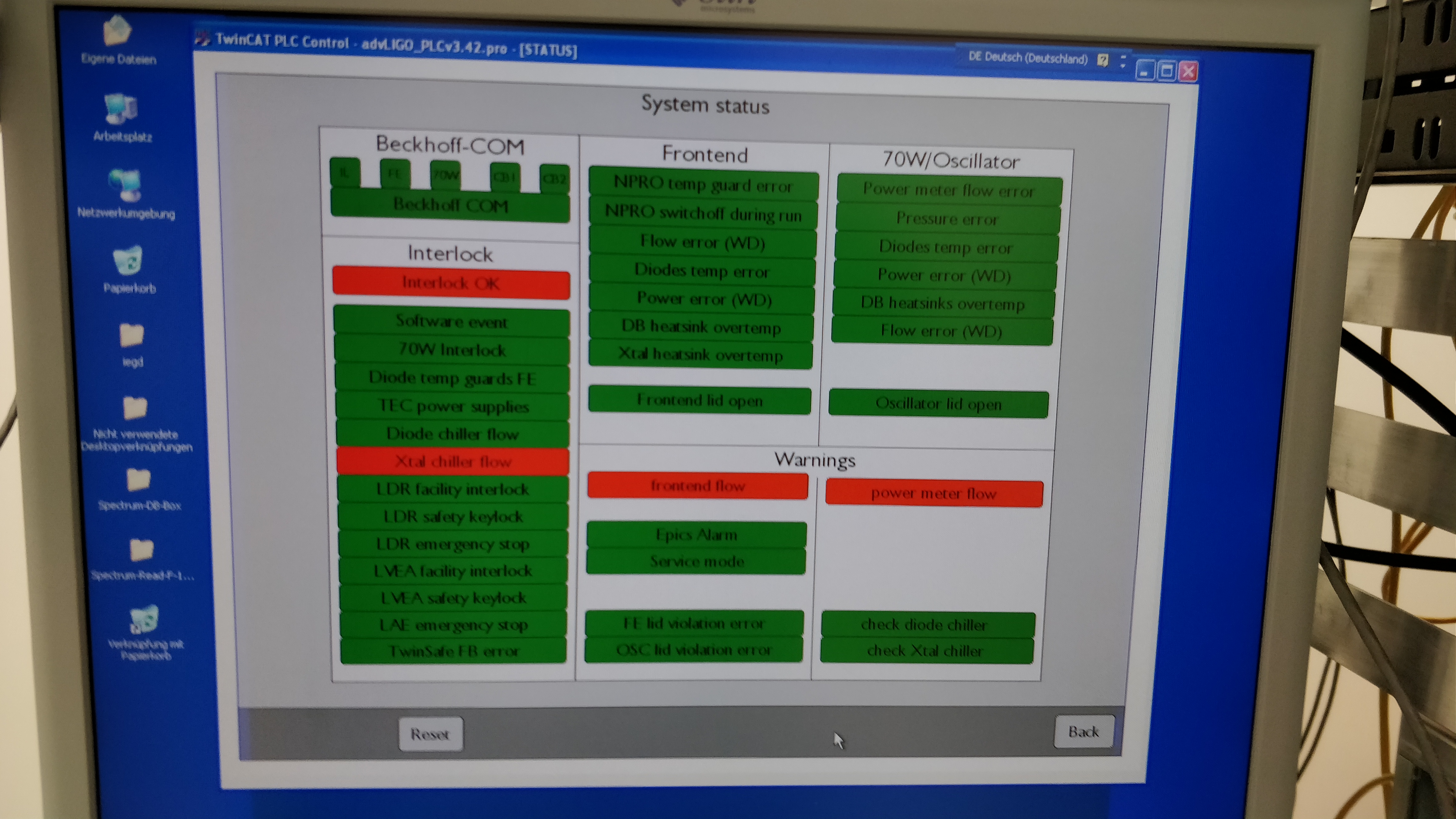
Image attached of the status screen when we got in to the diode room.
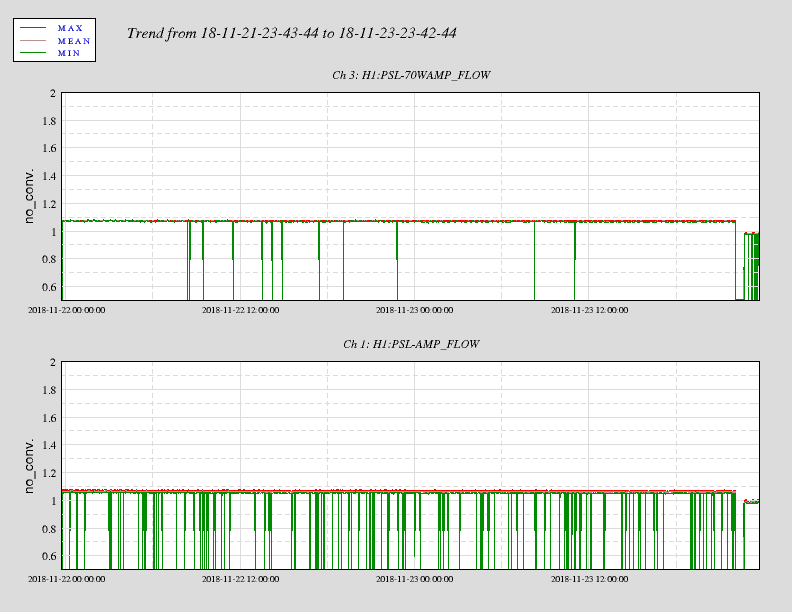
Attaching a screenshot of the flow meters for the power meter, amplifier, and 70 W amplifier. They're showing similar behaviour to what Jason reported in alog 45334.
There were occasional glitches in the flow meters, a drop when the chillers tripped, when we topped up the chiller and brought it back online around t-1250, the flow levels are lower than they were, and the power meter flow rate is very glitchy.
Y-end VEA and CS LVEA
I expect to be here for < 1 hr. and will make a comment to this entry when I leave.
At some point (later today? tomorrow?) PT110 will change voltage ranges and will then be showing comparatively lower pressure values. After this occurs it will be helpful to revisit the state of the alarm texting system such that the Vacuum group receive alarm texts should PT100 or PT110 indicated pressures exceed X torr -> where "X" is the preset, traditional threshold pressure value (5 x 10⁻⁶ torr?).
0725 hrs. local -> Leaving site now
The nominal high alarm levels for PT100 (HAM1) and PT110 (HAM6) are 5.0e-05 Torr. Both of these gauges are currently in the 2.0e-06 Torr range. We can either wait until they drop below 5.0e-05 Torr or raise the alarm level to re-engage the cell phone alarms.
Pressures are below 1x10⁻⁵ Torr in both HAM 1 & 6 and safe to turn on high voltage supplies.
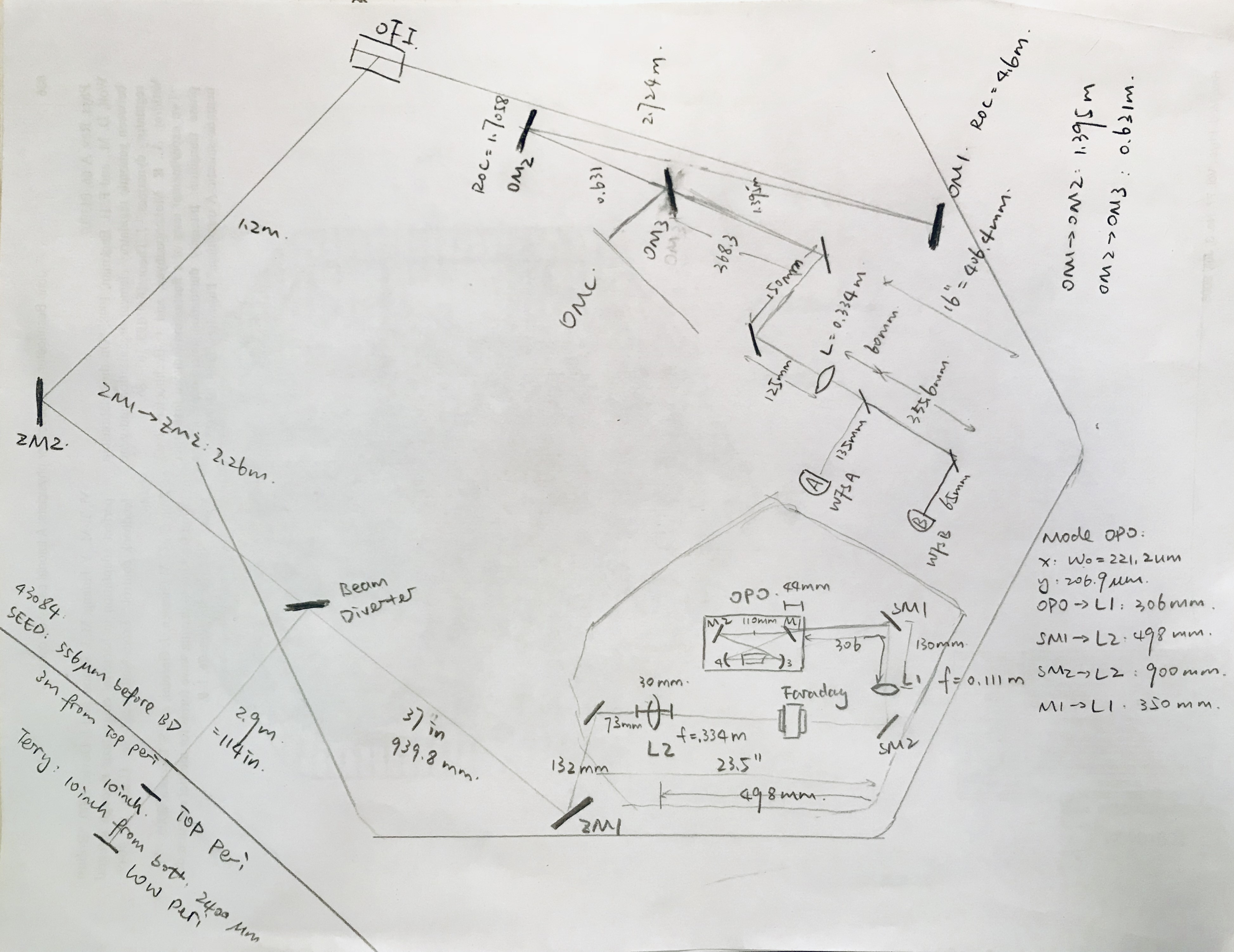
Made a drawing summary on SQZ distances measured. Will try to make a e-version later.
Can also be found at https://git.ligo.org/haocun.yu/lho_squeezing/wikis/VOPO
[Kyle, Gerardo, Chandra]
The day started with pumping HAM6, followed by HAM1 (after some cart controls troubleshooting by Kyle), along with pumping HAM 1,2,5,6 annulus volumes, and the team also managed to remove and replace ion pump #2, and install its chevron baffle.
We pumped on IP2, but its helium background is high, so we left leak detector valved in and plan to leak check on Monday. We also still need to leak check HAMs 1&6 new feedthroughs.
One of us will make a log entry when it is safe to turn high volts ON in HAM6 (and HAM1) for crews coming in over the weekend. PT-110 (on HAM6) and PT-100B (on HAM1) must read below 1x10⁻⁵ Torr.
All cleanrooms are OFF and VE decoupled from BSC10 annulus at EY.
Excellent work, vacuum team! ![]()
Did anyone track nipple and baffle serial number information?
Yes, ASSY-D1600431-005.
I finally got around to processing the data from the TFs that Jeff and I took on Monday (alog45418). OPOS, OMC, OMs, and ZM1 all still look good.
Chandra has requested that HAM1 and HAM6 cell phone alarms be bypassed until Monday (email alarms are unaffected).
Bypass will expire:
Mon Nov 26 15:13:11 PST 2018
For channel(s):
H0:VAC-LX_Y0_PT110_MOD1_PRESS_TORR
H0:VAC-LY_X0_PT100B_PRESS_TORR
Cheryl, Jason
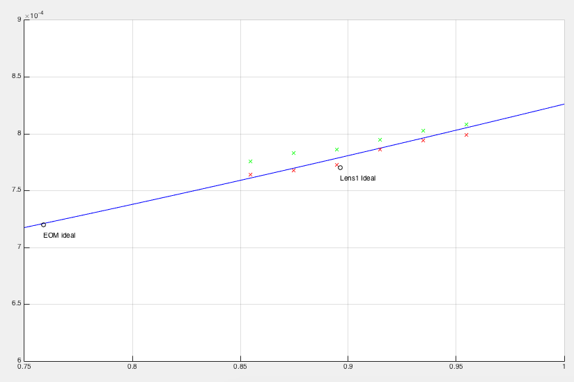
plots of data for PMC, ideal, and measured, and beam scan data collected yesterday, as well as distances used for the plots in a matlab .m file, and a huge image (7.5MB).
beam scan data from the bottom periscope is attached, distances are from the PZT, and the lens after the bottom periscope mirror is ~238.5mm from the PZT.
DUE TO SPACE AND COOLING LINE ISSUES, the original power readings were done with a power meter head that is supposed to be water cooled, but currently isn't. The readings from yesterday matched very closely the power out of the PMC that was measured with the water cooled beam dump, and were consistent when running the power to max and min at the bottom periscope. The plan for today was to use the air-cooled power meter head that can go to 50W, that we borrowed from TCS (TVo), to verify power at the bottom periscope mirror and the PMC.
J. Kissel, T. Shaffer
All of the suspensions in HAM6 have been given the okay based on the ran transfer functions listed below. OM2 needed a cable to be repositioned by Hugh on the vacuum side of the feedthrough. These measurements still need to be processed in MatLab, but file names for the good measurements are listed below. These are located in the appropriate areas in the sus svn. They are the xml files for now (I incorrectly exported many of them so I will check on that tomorrow):
2018-11-19_2130_H1SUSOMC_M1_WhiteNoise_V_0p01to50Hz.xml
2018-11-19_2130_H1SUSOMC_M1_WhiteNoise_T_0p01to50Hz.xml
2018-11-19_2130_H1SUSOMC_M1_WhiteNoise_L_0p01to50Hz.xml
2018-11-19_2130_H1SUSOMC_M1_WhiteNoise_R_0p01to50Hz.xml
2018-11-19_2130_H1SUSOMC_M1_WhiteNoise_Y_0p01to50Hz.xml
2018-11-19_2130_H1SUSOMC_M1_WhiteNoise_P_0p01to50Hz.xml
2018-11-19_2130_H1SUSOPO_M1_WhiteNoise_Y_0p02to50Hz.xml
2018-11-19_2130_H1SUSOPO_M1_WhiteNoise_V_0p02to50Hz.xml
2018-11-19_2130_H1SUSOPO_M1_WhiteNoise_T_0p02to50Hz.xml
2018-11-19_2130_H1SUSOPO_M1_WhiteNoise_L_0p02to50Hz.xml
2018-11-19_2130_H1SUSOPO_M1_WhiteNoise_P_0p02to50Hz.xml
2018-11-19_2130_H1SUSOPO_M1_WhiteNoise_R_0p02to50Hz.xml
2018-11-19_2117_H1SUSOM1_M1_WhiteNoise_L_0p02to50Hz.xml
2018-11-19_2117_H1SUSOM1_M1_WhiteNoise_P_0p02to50Hz.xml
2018-11-19_2117_H1SUSOM1_M1_WhiteNoise_Y_0p02to50Hz.xml
2018-11-20_0025_H1SUSOM2_M1_WhiteNoise_L_0p02to50Hz.xml
2018-11-20_0025_H1SUSOM2_M1_WhiteNoise_P_0p02to50Hz.xml
2018-11-20_0025_H1SUSOM2_M1_WhiteNoise_Y_0p02to50Hz.xml
2018-11-19_2149_H1SUSOM3_M1_WhiteNoise_L_0p02to50Hz.xml
2018-11-19_2149_H1SUSOM3_M1_WhiteNoise_Y_0p02to50Hz.xml
2018-11-19_2149_H1SUSOM3_M1_WhiteNoise_P_0p02to50Hz.xml
2018-11-12_1849_H1SUSZM1_M1_WhiteNoise_L_0p02to50Hz.xml
2018-11-12_1849_H1SUSZM1_M1_WhiteNoise_Y_0p02to50Hz.xml
See alog45456 for the processed results.