The goal of this entry is to describe a method to characterize the non stationary of SRCL noise coupling to DARM, by identifying the coupling modulation. In the near future this should also provide a technique to do non-stationary noise subtraction.
When SRCL noise is injected and the SRCL feed-forward path is active, we see
In the plot below, the coherence is computed while SRCL noise was being injected.
The observations above seems to hint to some non-linear or non-stationary coupling of SRCL to DARM, especially at frequencies above 20-30 Hz
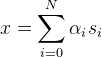
Past observations showed the SRCL coupling to be modulated by residual angular motion. To characterize this more precisely, I used the following algorithm:

Although the alpha_i are frequency dependent, they are not enough to describe any frequency dependency in the way the angular signals are affecting DARM. For example, if one of the angular signals modulates the coupling with a delay, or after the signal is passed through any time-domain filter, this algorithm will not model that. In other words, this algorithm is capable of finding and modeling things like DARM = TF[ SRCL * ASC_i] but not like DARM = SRCL * TF[ASC_i].
This algorithm is essentially equivalent to implementing an a-causal Wiener filter that uses as input the modulated signals s_i
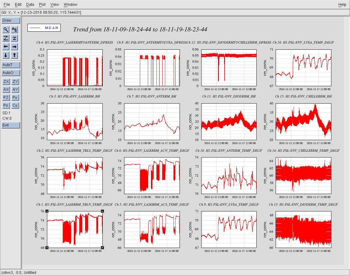
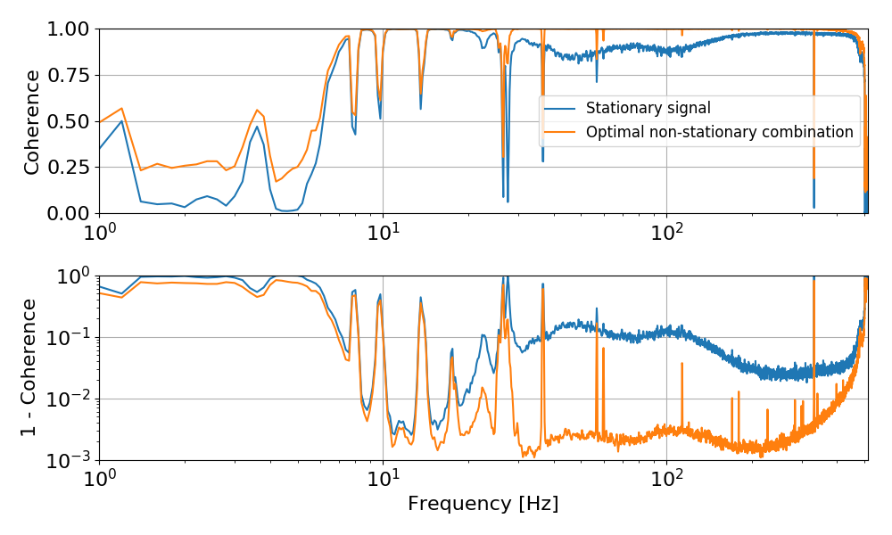
The two plots below shows the effectiveness of this algorithm. While the coherence of DARM with SRCL is relatively low during the noise injection, the coherence of the (optimally) modulated signal is high everywhere, as one would expect given the SNR of the noise injection. The second plot shows that if we subtract SRCL from DARM using a constant transfer function (i.e. DARM - TF * SRCL) we cannot get more than a factor ~10 subtraction. However, if we use the signal x that takes into account the modulation, we can get a much improved subtraction at all frequencies. For comparison the plot shows a typical level of DARM noise.
The algorithm work in frequency domain, so for each of the modulation channels (SRCL times a_i or a_i^2), we get a transfer function that determines how that couples into DARM. I don't have a way yet to rank the most important modulations, but simply looking at the amplitude of the transfer function gives an idea of which angular signals are the most important. The plot below shows the amplitude and phase of each transfer function. So the title of each panel gives you the source of the modulation (1 means no modulation) and the plot is actually the transfer function from SRCL times that modulation to DARM.
The most important modulations are: DHARD_P, DHARD_Y followed by SRC1_P, MICH_P and PRC2_P
This algorithm does not provide yet a way to build a time domain subtracted channel. To do that we have to convert the transfer functions to time domain filters.
I will try out (1) in the near future. (2) can be left as a fallback solution, since it's known to be working.
I have some plans to try (3), which is the most interesting of the three approaches. If working, it might also provide a way to directly gte IIR filters from the Wiener algorithm.
Finally, sooner or later, I will prepare a write-up of the algorithm for the DCC.
J. Kissel, after conferring with F. Clara, S. Dwyer, M. Pirello, D. Sigg, and J. WarnerMarc informs me that he and Fil have completed the standard checks for pins shorting between ground and chamber, and ground and any signal pins, aka "ground loop" checks on all SUS inside HAM6, and those tests have passed.EDIT: Some confusion betwen verbal communications. There are SUS that were not yet checked at the time of (previously) writing the aLOG. There are some shorts that we're currently investigating delaying the closure of HAM6. We've punted on checking any ISC sensors, namely - LSC OMC DCPDs - ASC OMC Input QPDs - ASC AS A & B WFS - ASC AS C QPD - SQZ Green & CLF rejected polarization PDs because (a) Sheila & Co. did not touch (i.e. disconnect or reconnect, or move any cable routing) any photodiode cables. (b) If there were problems with these cables, we wouldn't be able to reach the feedthroughs and cable routing in order to fix them. Sheila and Daniel sign off on this decision. The last time this chamber has been checked thoroughly was at the close-out of the Sep 2017-Jun 2018 vent; see LHO aLOG 41709, in which Keita found many ISC sensors shorted to the chamber, and fixed all of them. We also punted (and always punt) on checking seismic sensors, because they "by design" intentionally grounded everything to the chamber inside, instead of at at the rack like ISC and SUS.This makes "ground loop" checking in HAM6 complete.Investigation on going.
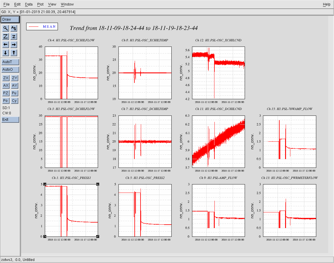
Both chillers are still currently overfilled. No water was added. The logs were updated.
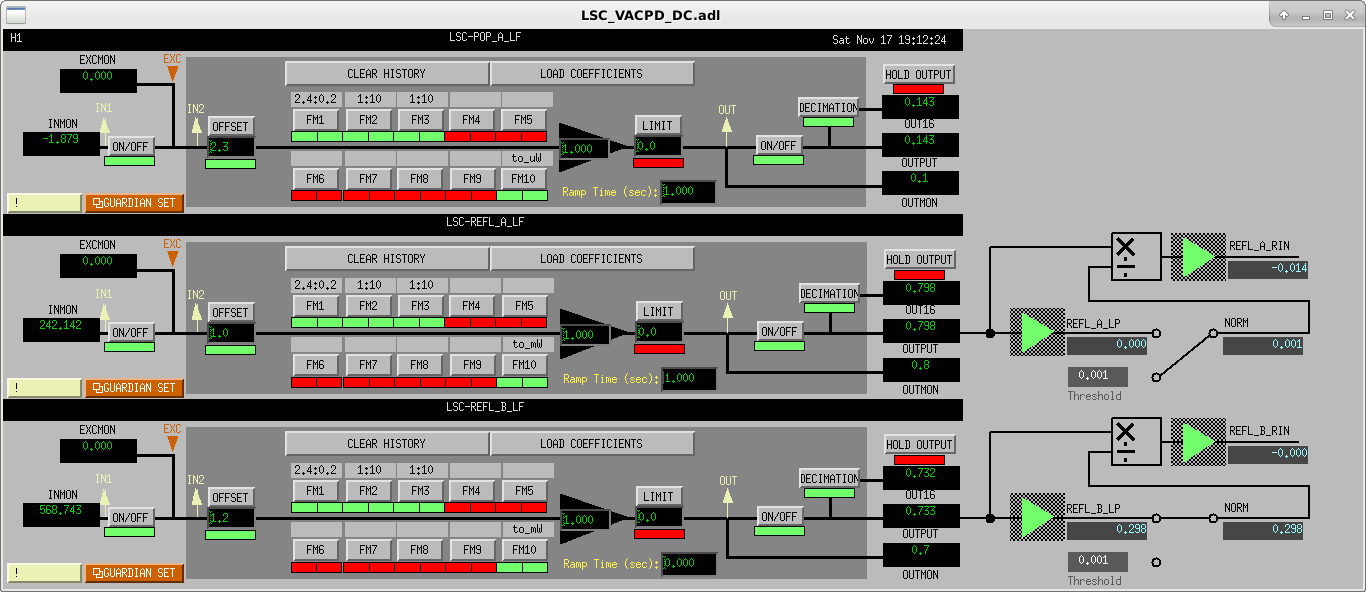
Dither alignment for soft loop: ====================== Instead of doing A2L decoupling repeatedly LLO does control the soft loops DC continuously using 8 dither lines between 7 and 9 Hz. That system seems to work well for them. LHO currently uses the end station QPDs, as well as effectively the POP QPD to fix the DC positions. While I have no indication that LHO's system is unreliable, I have noticed that S2L seems to change when we change arm power. So I would suggest just copying LLOs dither system - at least as independent diagnostics. WE can still decide whether or not we want to run with it continuously. LSC DC DQ channel: =============== H1:LSC-POP_A_LF_OUT_DQ H1:LSC-REFL_A_LF_OUT_DQ and H1:LSC-REFL_B_LF_OUT_DQ are currently only recorded at 2048Hz in Hanford. Those channels have interesting information about intensity noise and RF sideband intensity noise at higher frequencies, and should be recorded at 16384Hz (that's what they are at LLO).
WP7954 Dolphin Upgrade.
In preparation for an upgrade, I am rebuilding the H1.ipc IPC Table File from scratch.
Please do not recompile or restart any models over the next 24 hours.
Now I'm checking all the models compile before we change anything.
Bypass will expire:
Tue Nov 20 11:44:41 PST 2018
For channel(s):
H0:VAC-LX_Y0_PT110_MOD1_PRESS_TORR
H0:VAC-LY_X0_PT100B_PRESS_TORR
After discussion with Chandra, we have extended this to Wednesday when we will review the alarms for the holiday period.
Bypass will expire:
Wed Nov 21 12:27:49 PST 2018
For channel(s):
H0:VAC-LX_Y0_PT110_MOD1_PRESS_TORR
H0:VAC-LY_X0_PT100B_PRESS_TORR
Ryan, Carlos, Jonathan
At 18:56 UTC today, while following up on a note from LLO aLOG #41844 , one of the processes on the core router responsible for maintaining connectivity with our Internet providers encountered a segmentation fault. Carlos and Jonathan were called and they connected to the console to debug with me. The routing process was restarted and reconnected to our providers at 19:10 UTC. I believe this is directly related to the connectivity issues that Keith logged Friday night / Saturday morning and am checking for updates that may be related to the routing process crash issue.
FRS #11860 filed.
Likely related recurrence today around 19:25:40-08:00. System rebooted itself without intervention. This may be failing hardware; we have a cold standby available to swap in.
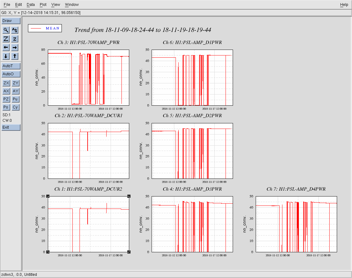
Laser Status:
Front End Power is 33.75W (should be around 30 W)
70W Output Power is 71.1W
Front End Watch is RED
70W Watch is GREEN
PMC:
It has been locked 0 days, 0 hr 9 minutes (should be days/weeks)
Reflected power = 10.57Watts
Transmitted power = 58.87Watts
PowerSum = 69.43Watts.
FSS:
It has been locked for 0 days 0 hr and 0 min (should be days/weeks)
TPD[V] = 0.05622V (min 0.9V)
ISS:
The diffracted power is around 0.15%
Last saturation event was 0 days 0 hours and 14 minutes ago (should be days/weeks)
Possible Issues:
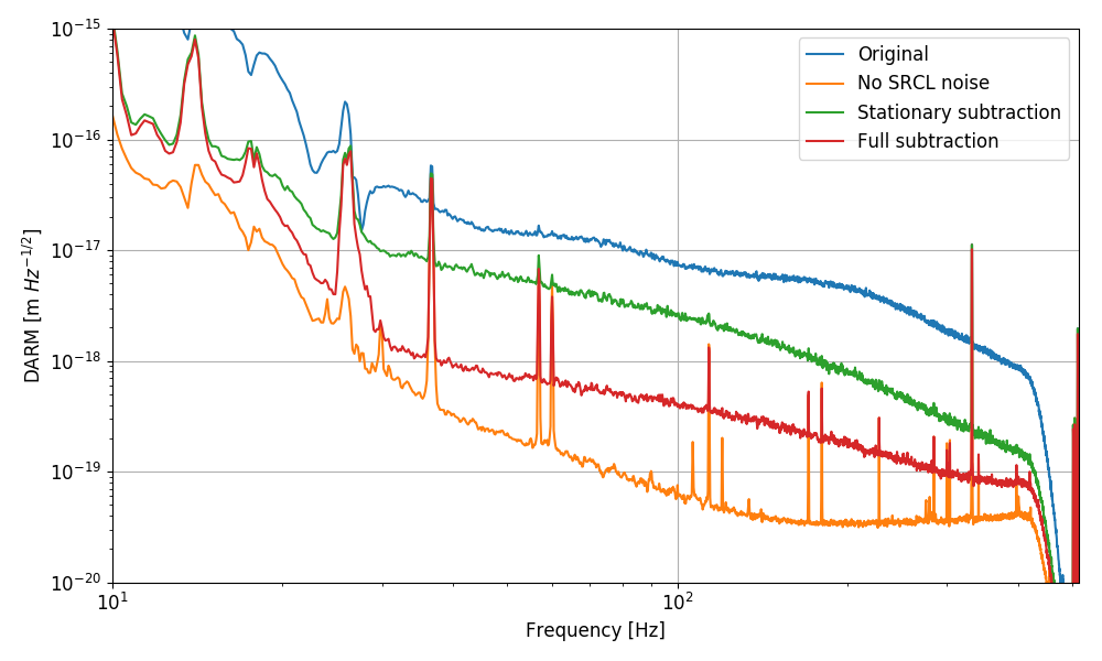
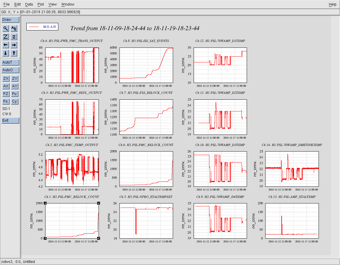
Vent activities/PSL table work are the dominating feature in all plots this week, folks.
LVEA is LASER HAZARD - light pipe is currently CLOSED
HAM1 closeout tasks: Ground loop checks; measurements; labeling of L4C cables
HAM6 - TF's currently running
TFs on HAM6 will de delayed until gnd loop checks are done
PeterK, RickS
Jason tweaked the alignment into the 70-W amp a bit late Friday afternoon. It seemed that the pedestal in the 70-W output beam had been reduced and the beam didn't look too bad.
Today, we aligned into the PMC, adjusted the modematching lenses, adjusted the 70-W diode temperatures, and adjusted the pump currents.
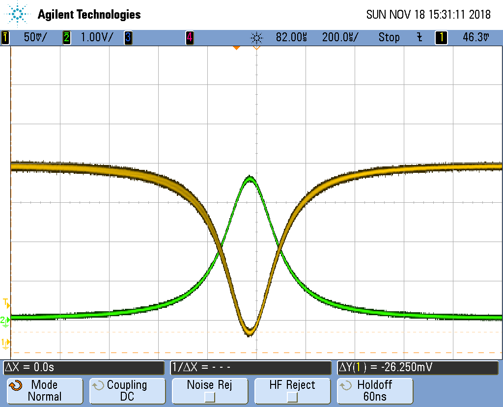
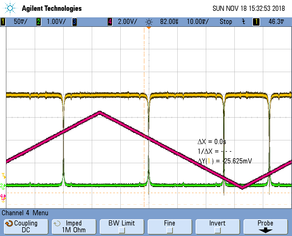
We now have about 60 W (59.9 W) in transmission with about 10 W (9.7 W) reflected from the PMC. This is about 86% visibility using the power monitors. The visibility measured with the DC out of the RFPD (using the no-light level when the PD is blocked, about 14 mV) is (238-26)/238 = 89% (see attached scope image). An improvement over what we had last week.
The ~60 W in transmission is close to what we need for O3.
The FSS is locked, but the ISS AOM is still removed from the beam path so the ISS is inoperable.
Forgot to mention that we cleaned a number of relay mirrors in the main path that had bright beam spots when inspected with an IR viewer. This needs some more attention and a few might need to be replaced.
Transmission and reflection photodiode outputs.
K. Kawabe, J. Kissel, G. Mansell, D. Sigg
We've achieved the following in HAM1 today:
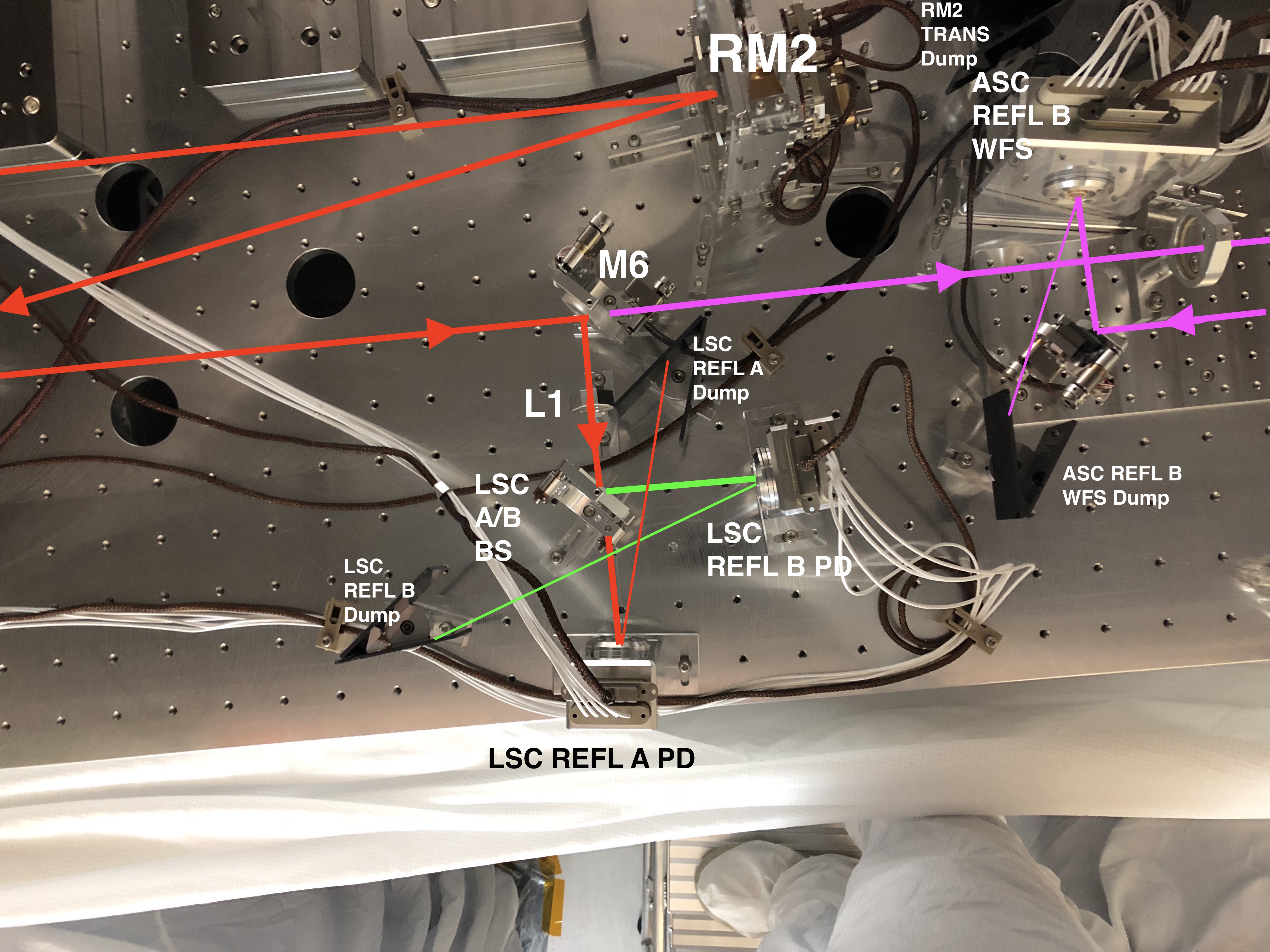
- Measured beam profile on LSC side (reflection side) of LSC/ASC REFL Beam Splitter (M6 on D1000313) down stream of the lens L1 (without LSC REFL A or LSC REFL B, or LSC A/B beam splitter in place)
- Re-installed LSC REFL A/B beam splitter, and LSC REFL A PD
- Installed new LSC REFL B PD
- Aligned beams on to LSC REFL A and B using LSC/ASC beam splitter, LSC A/B beam splitter
- Aligned LSC REFL A and B PD such that their reflections are dumped appropriately
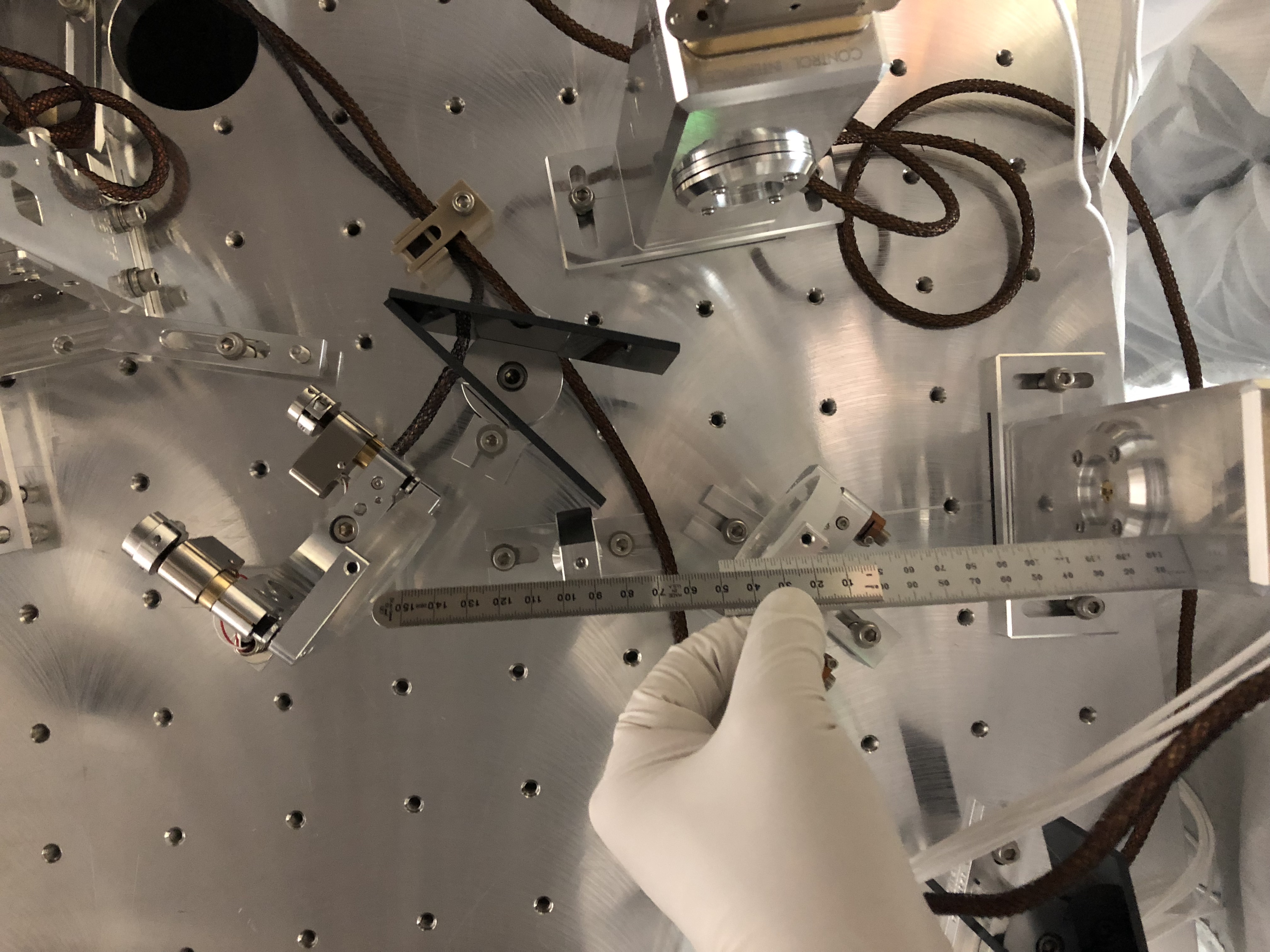
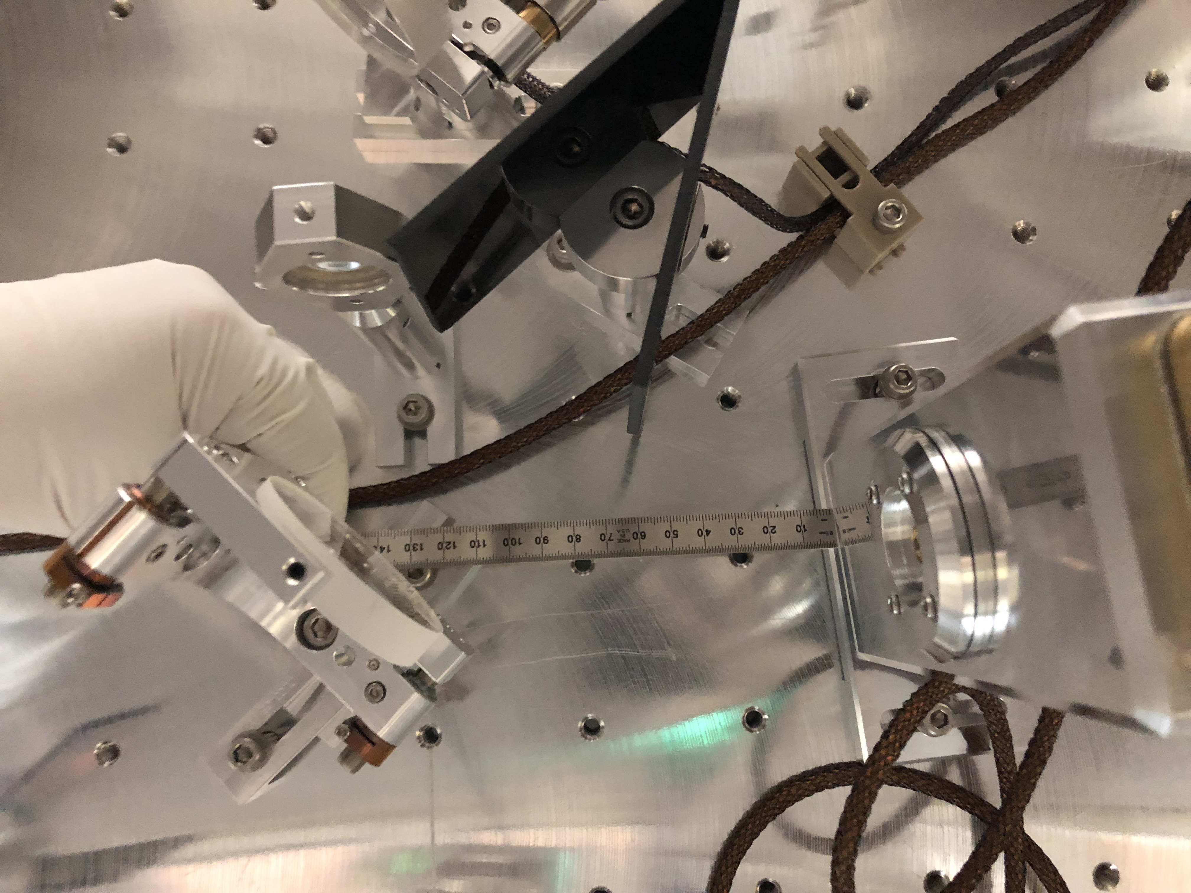
- Verified the distances between LSC A/B beam splitter and each PD which we believe will result in a beam radius of ~240 um (details to be posted later)
- WFS B beam dump black glass** has been replaced, as discussed in LHO aLOG 45279
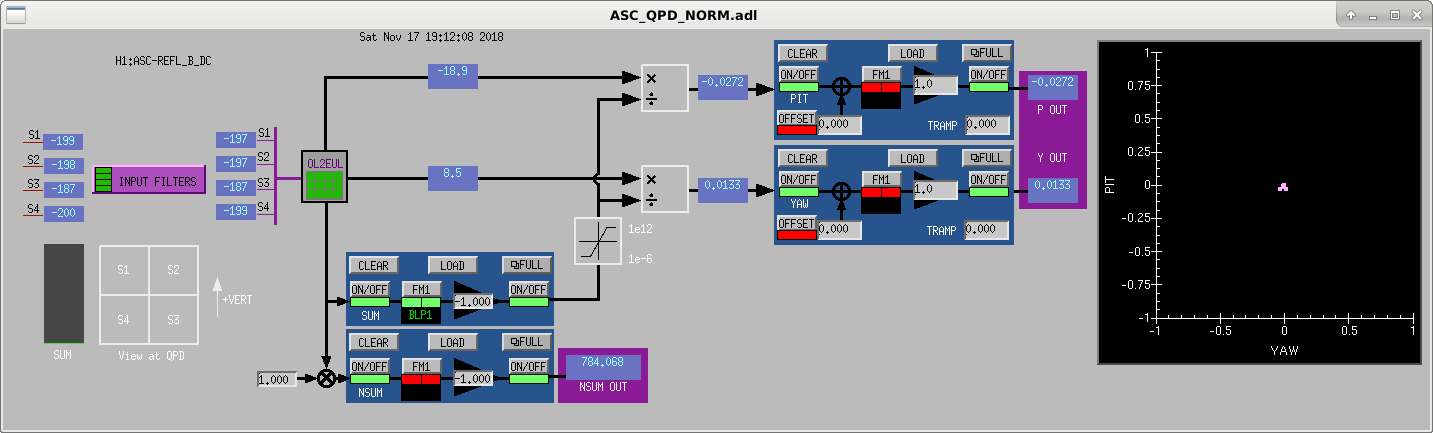
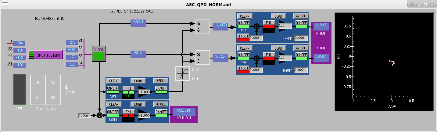
- We found that physical ASC REFL B was read out in the digital system as ASC REFL A (both DC and RF), and vice versa
- Attempted to figure out what was wrong with ASC REFL A segment 4 DC, tried many things including various cable swaps, ended up reverting to the original configuration as we found it. DB25 for physical ASC REFL B (digital ASC REFL A) was not secured at all. This was reseated and secured. This somehow repaired the faulty segment, but we can't really identify exactly what fixed it.
- We measured the laser power at various points in HAM1 with a dodgy OPHIR power meter:
IMC_PWR_IN reports 250 mW.
Inside HAM1, that same input beam as it flies through HAM1: 234 mW
IFO REFL beam coming back into HAM1: 227 +/- 50 mW
REFL AIR path: 4.1 +/- 0.5 mW
In front of LSC REFL A: 1 +/- 0.5 mW
In front of LSC REFL B: 0.87 +/- 0.5 mW
LSC-REFL_A_LF_OUT16 reports 0.8 +/- 0.01 mW
LSC-REFL_A_LF_OUT16 reports 0.735 +/- 0.01 mW
- We checked all new components for being bolted to the table, and we cleared the table of all tools we used today.
**The existing black glass stock all appear to have water marks of some sort, so Keita took the best he could find, and used a pre-soaked wipe to clean off what fogginess he found.
We have left the IFO with both the main PSL input light pipe and the ALS light pipe shuttered.
What's left to be done:
- Verify that LSC REFL A and B's RF signals are functional (we only verified that DC signals are functional). Currently the cable that connects the TNC to 5-way coax piece is missing at the chamber feedthrough.
- The chamber-closeout ground loop check
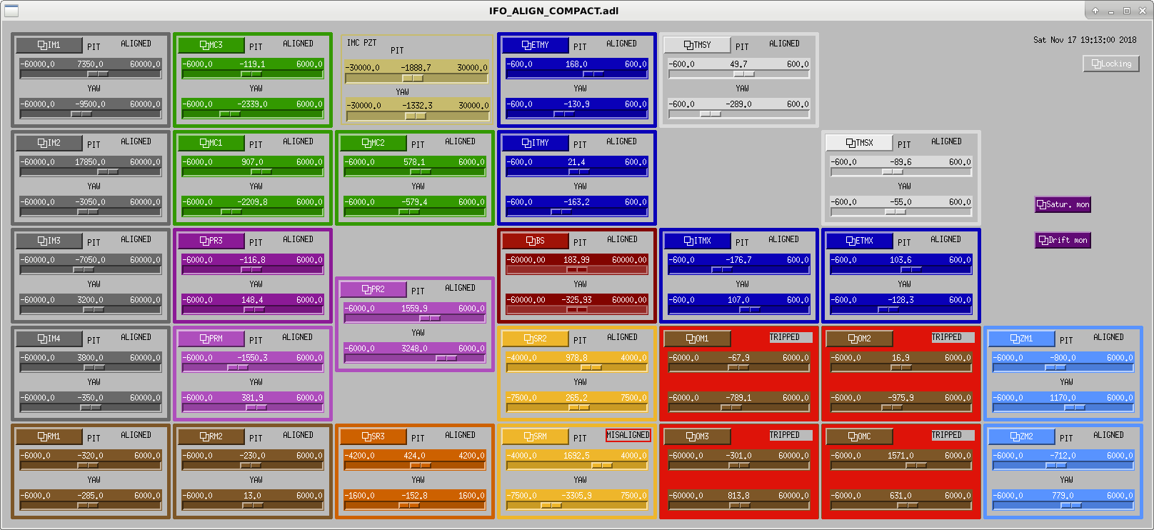
Detailed blow-by-blow log is attached. Also attached are some relevant screen captures of the state of things after we'd finished with the IMC locked on 250 mW input power, the IMs, RMs, and PRM aligned, and with the REFL DC centering loops engaged.
Pictures, and plot of LSC REFL path beam radius evolution to come in a bit.
We know that LSC-REFL_A RF is working. Only LSC-REFL_B needs checking.
We found the 5-way coax to TNC adapter made by Fil in the shop (but we didn't have stamina to continue).
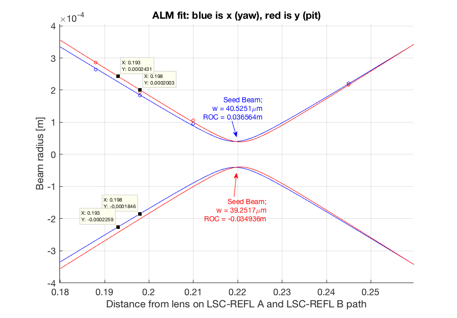
- Attaching the beam profile on the LSC-REFL PD path, as measured from lens L1. The LSC-REFL_A was placed 193 mm from the lens (if I remember correctly, Jeff will correct me if I'm wrong). When including the extra ~5mm optical path through the beamsplitter, which was not included in this beam scan, the beam radius at the photodiode surface should be ~200 um.
- Also attaching serial numbers and part numbers of the power meter (PD300-3W-SH) used to measure numbers quoted by Jeff above. We were tried two head/filter combinations and had some concerns about systematic uncertainty introduced by mismatched pairs of heads and filters.
| Part number | Serial number | |
|
Head |
1202411 | 73375 |
|
Filter |
1Z02411 |
64799 |
|
Display |
Z01500 | 120573 |
This alog addresses IIET 4526: Bad connection at D6 1C1 feedthrough on HAM1 (ASC-REFL_A_DC_SEG4 problem).
The feedthrough was switched earlier, alog 45337. On Saturday, we swapped the DB25 cables bewteen the REFL WFS to see, if the problem stays with the cable connection or the sensor head. After some confusion, we concluded the problems had disappeared. Not sure, if this was due to the feedthrough work or the connector swap at the head. We swapped the cable back to nominal, and we inserted breakout boards at the WFS interface chassis. There, we verified that each leg of all 4 DC signal readbacks of both WFSs were operational. We will check again after pump down, but for now the problem looks fixed.
For REFL the downstream WFS is A, whereas the upstream WFS is B. This is contrary to the usual convention, but it has always been like that and we didn't correct it during this vent.
Here're the collection of photos from the day. The full bank of photos can be found in the DCC under G1802204. I attach a few photo highlights, and those imperative information here.
A note on the beam profile measurement:
Keita reminded me that the photodiode surface protrudes from the case by 3.8 mm. The x axis on my beam profile fit is measured relative to the case. So the position of the diode is actally 3.8 mm before my guess in the above comment, at 194.2 mm. The beam radius here is (216, 232) um.
Danny V., Dan Brown, TVo
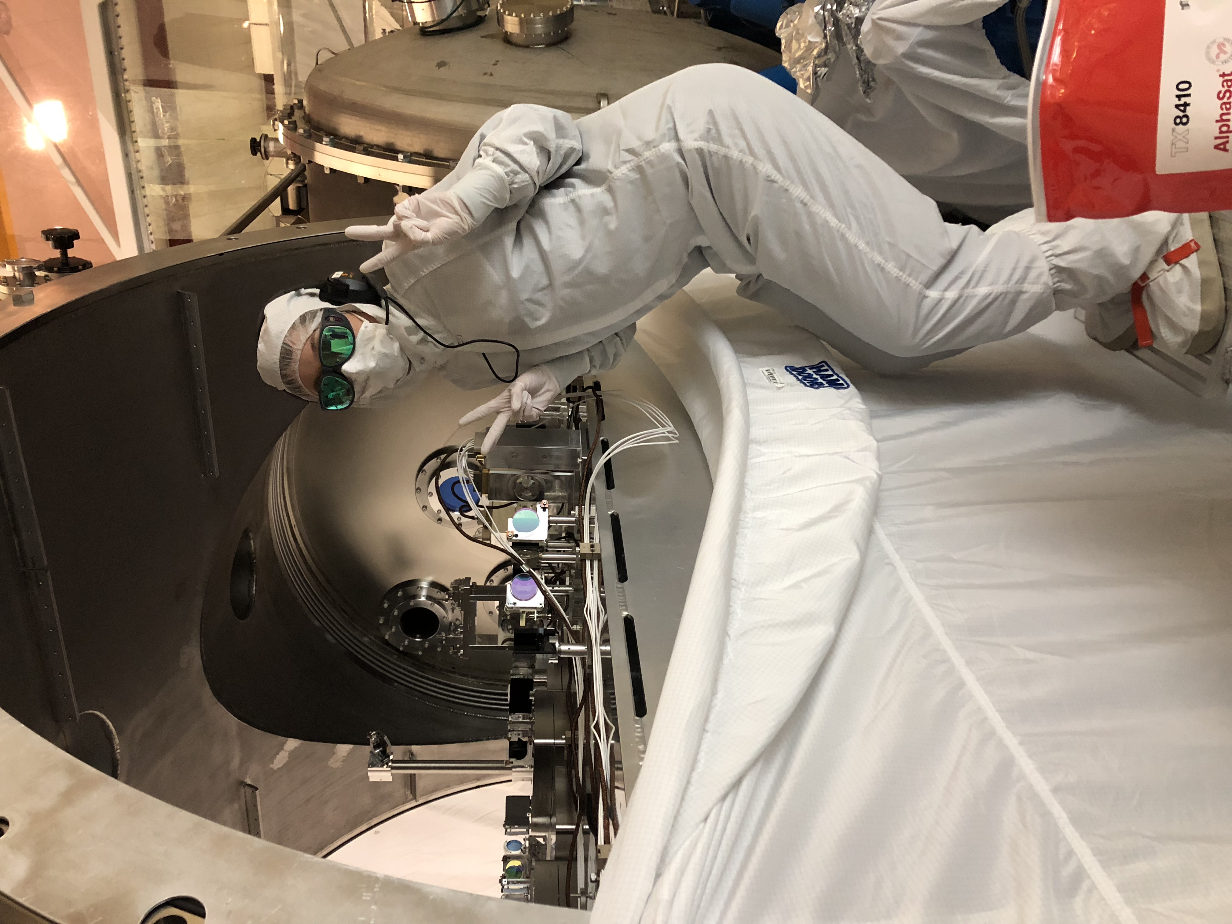
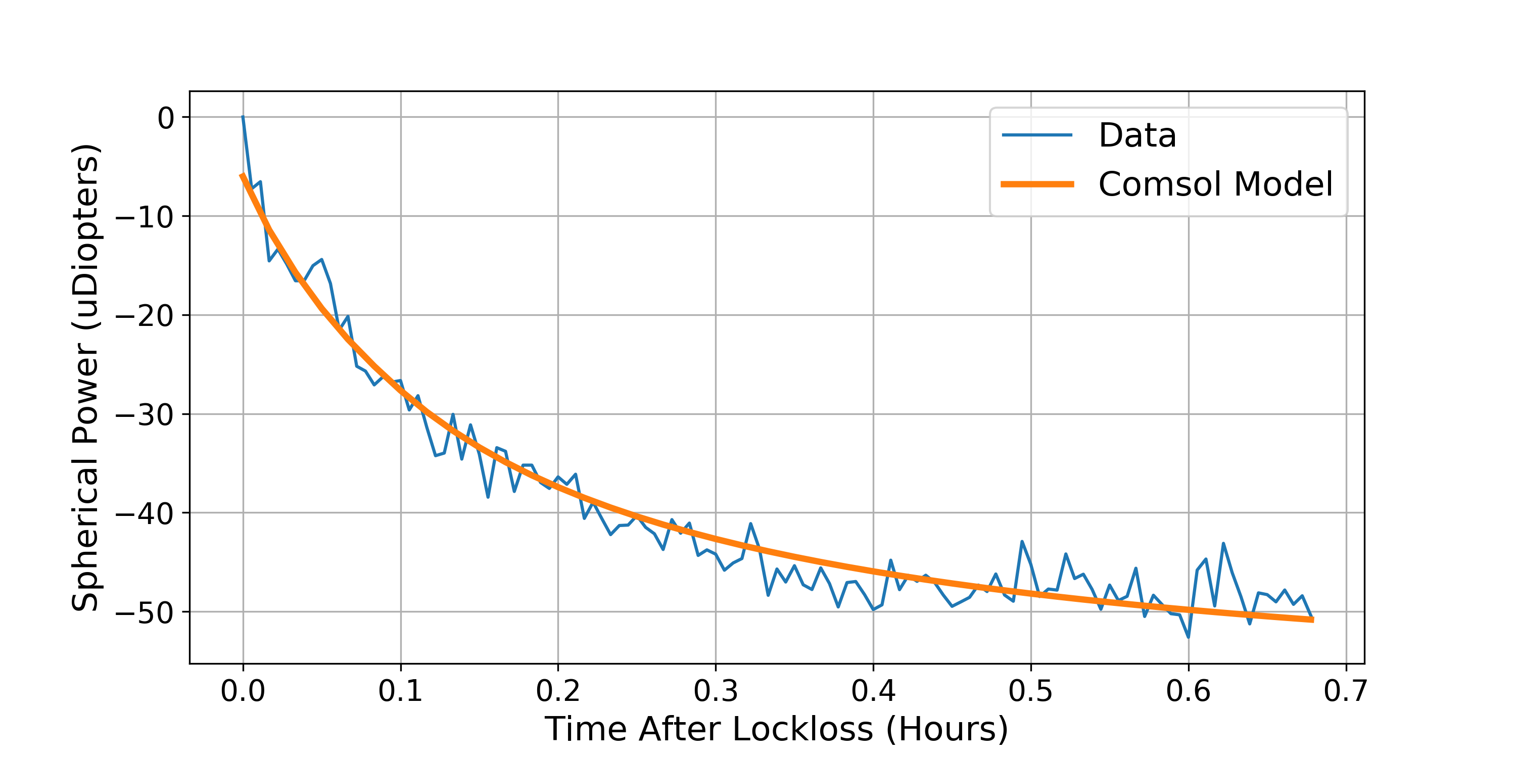
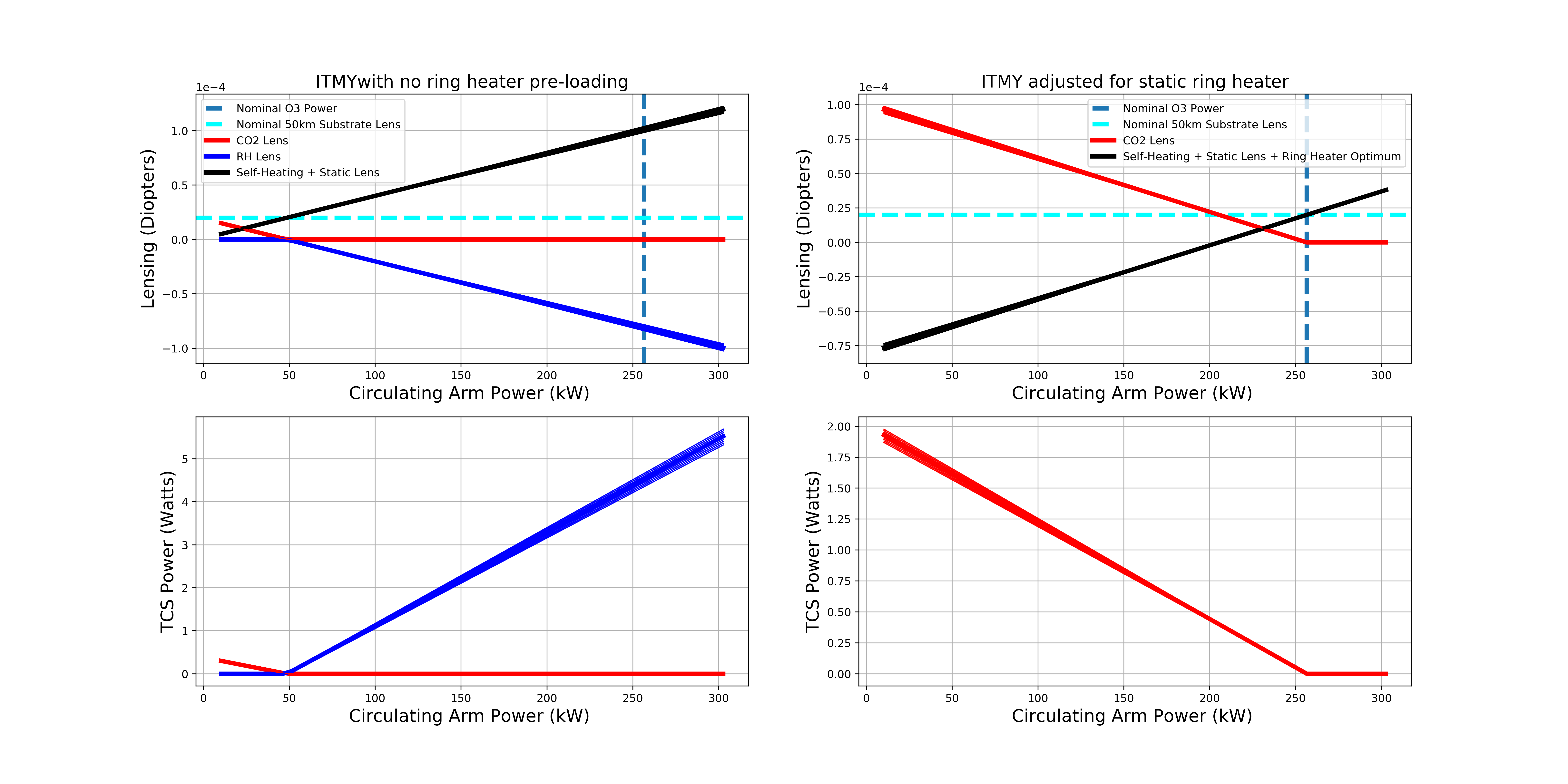
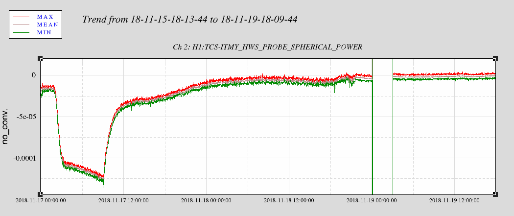
During one of the lock losses last week, we paused the CO2 compensation on both ITMs in order to get an absorption measurement with just IFO cooling. Also during this time, Dan did some post processing on the Hartmann data in order to better fit the spherical power to the wavefront distortion. Previously, the HWS code provided did not take into account for an offset in the IFO beam relative to the center of the Hartmann camera and Dan was able to add the ability to re-fit using the IFO beam as the center and this has cleaned up our data a lot. With this new data we use the exponential decay from a COMSOL model from this ALOG-14634 and provides a pretty good fit for both ITMs ( Figure 1 and 2), the largest uncertainty is estimated by varying the starting time for our fits from when the lock loss actually occurred because the optics swinging around caused a lot of noise in the Hartmann sensor. It should be noted that we haven't subtracted any point absorbers from the ITMY data which will over-estimate the amount of ring heater compensation, this means that we could have some CO2 left over at 50 watts for CO2Y.
ITMX absorption: 304 +/- 38 ppb
ITMY absorption: 804+/- 42 ppb
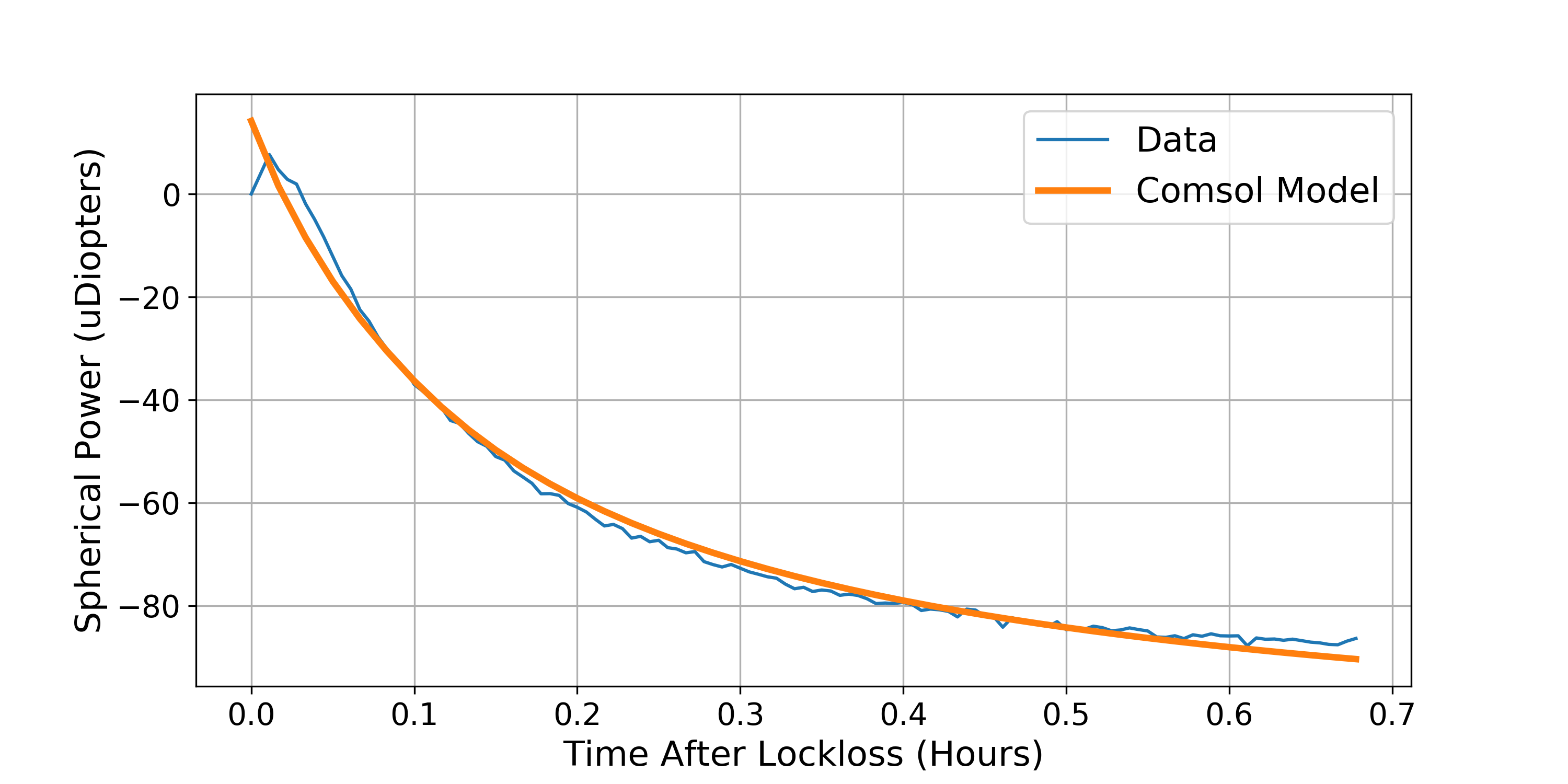
Figure 3 and 4 provide the pre-loading settings estimates for 50 Watts using this absorption data and some actuator calibrated numbers which we fine-tuned during this quiet vent break (while the corner is under vacuum but HAM1&6 are open) , interestingly, the amount of spherical power for ITMX-CO2 differs ITMY-CO2 by a factor of two according to the HWSs, we're still trying to track this down.
Parameters used to work out the TCS settings for O3 (diopters/watt):
#factor of 2 for the double pass
RH_SUBdef = -2*9e-6
#factor of 2 for the double pass
ITMX_CO2_SUBdef = 2*1.5e-5
ITMY_CO2_SUBdef = 2*2.5e-5
SelfSUBdef = 4.87e-4
# Parameters for surface deformation
RH_SURFdef = 9.91e-7
SelfSURFdef = -3.60e-5
Calculated O3 Actuator:
ITMX:
Self Lensing is 41.2594 uDiopters Required RH Lensing is -0.0 uDiopters RH Power required is 1.1811 Watts CO2 Lensing required 42.9709 uDiopters CO2 Power required 1.4324 Watts
ITMY:
Self Lensing is 101.4137 uDiopters Required RH Lensing is -100.0 uDiopters RH Power required is 4.523 Watts CO2 Lensing required 100.4321 uDiopters CO2 Power required 2.0086 Watts
We can dial in the CO2 laser power now and when we have reached the Paschen limit, we will turn on the ring heaters and use the HWS to track the wavefront through this process.
Any ideas why the ITMX absorption value has increased by ~4 relative to the old value given in alog 43979, whereas ITMY looks consistent?
I made a mistake and swapped the ITMX, ITMY numbers around, this is fixed.
The Hartmann fitting code that takes the wavefront and fits a spherical power has improved because we were able to more precisely fit over interferometer beam in post-processing.. Previously, the Hartmann code would try to fit assuming the lensing occurred at the origin of the camera but we found that this caused some significant differences when the interferometer heating was offset so Dan was able to use saved images to reconstruct the calculation for the spherical lensing with better offsets by hand. Now this is implemented in the real-time code so our spherical power should be fitting around where we think the interferometer beam is.
We had aligned the Hartmann beam on the test mass using the ring heaters (which they still are), but found that this puts the IFO beam about 4cms to the right on the test mass as measured by the HWS. However, I don't think that's very physical which makes me question the centering of the ring heaters relative to the test mass
We should go back and revisit that data from the previous absorption measurement and implement this fix as well to see if our numbers hang together.
Attached is the preoloading for ITMY, the ring heater brings the spherical power down and the CO2 laser central heating brings the lensing back up towards zero. We probably overshot the CO2 compensation a bit so we can reduce it a little. The glitch at 00:00:00 is from mis-aligning ITMY so that's explainable.
After quick peeks at the TFs at closeout yesterday showed healthy suspensions, the door to the chamber was closed and pump downs started. Today, Travis and I ran the full set of Transfer functions for ETMY MAIN, REACTION, and TMSY suspensions (18 measurements). All plots look good and can be found at 2018-11-14* Files in the appropriate directories. Between Travis and I, we're a few hours into this today (running, exporting, troubleshooting matlab, etc) and I need to move on to other things, so pretty plots aren't going to be posted today, especially without the auto-renumbering scrip at my fingertips for the master plotting script. See the files if you want to look at them yourself although I still need to commit them to the svn.
Note, the alignment offsets were ON for these measurements.
Directory of measurements:
ligo/svncommon/SusSVN/sus/trunk/QUAD/H1/ETMY/SAMG0/Data/2018-11-14-1658_H1SUSETMY_*
or R0 and Results directory for processed matlab files.
Can't commit data to svn because it throws an error about upgrading svn. I was working on the "controls login. Maybe someone can fix this.