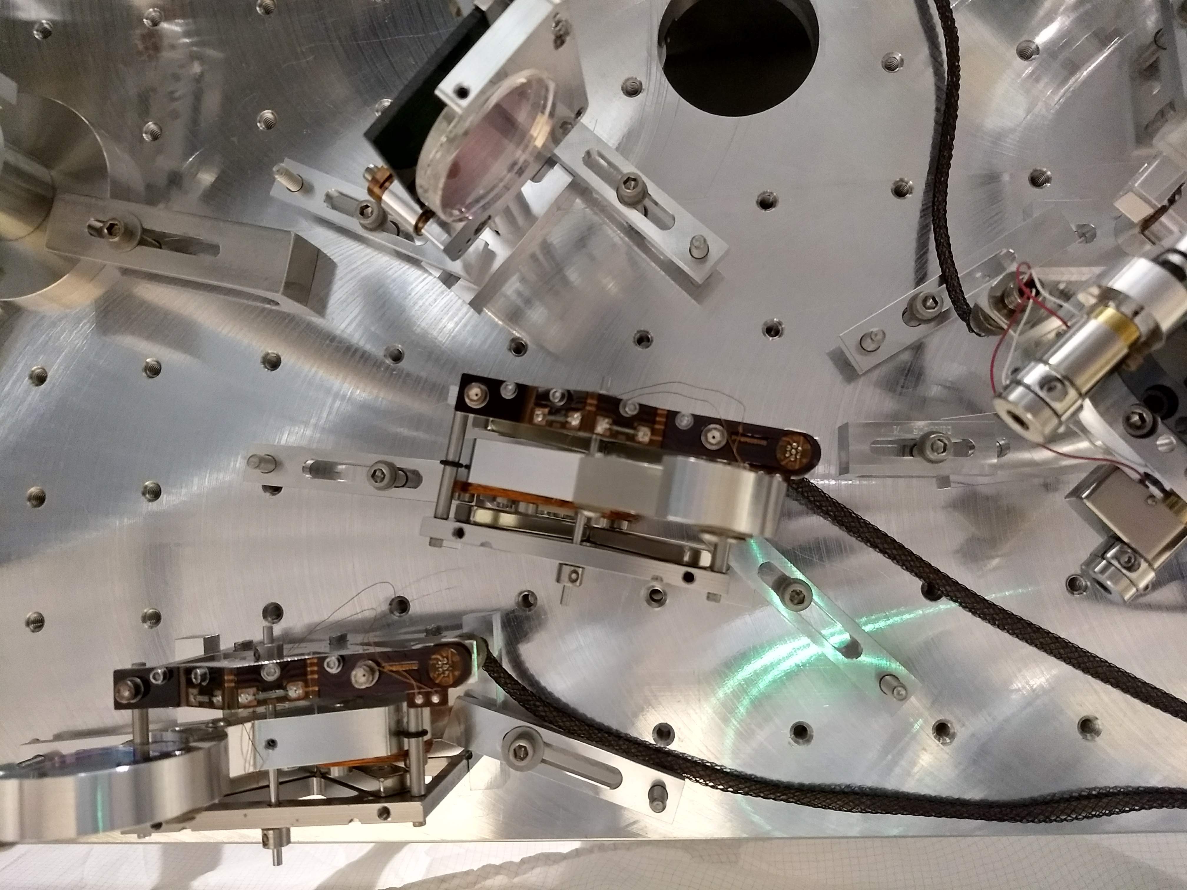
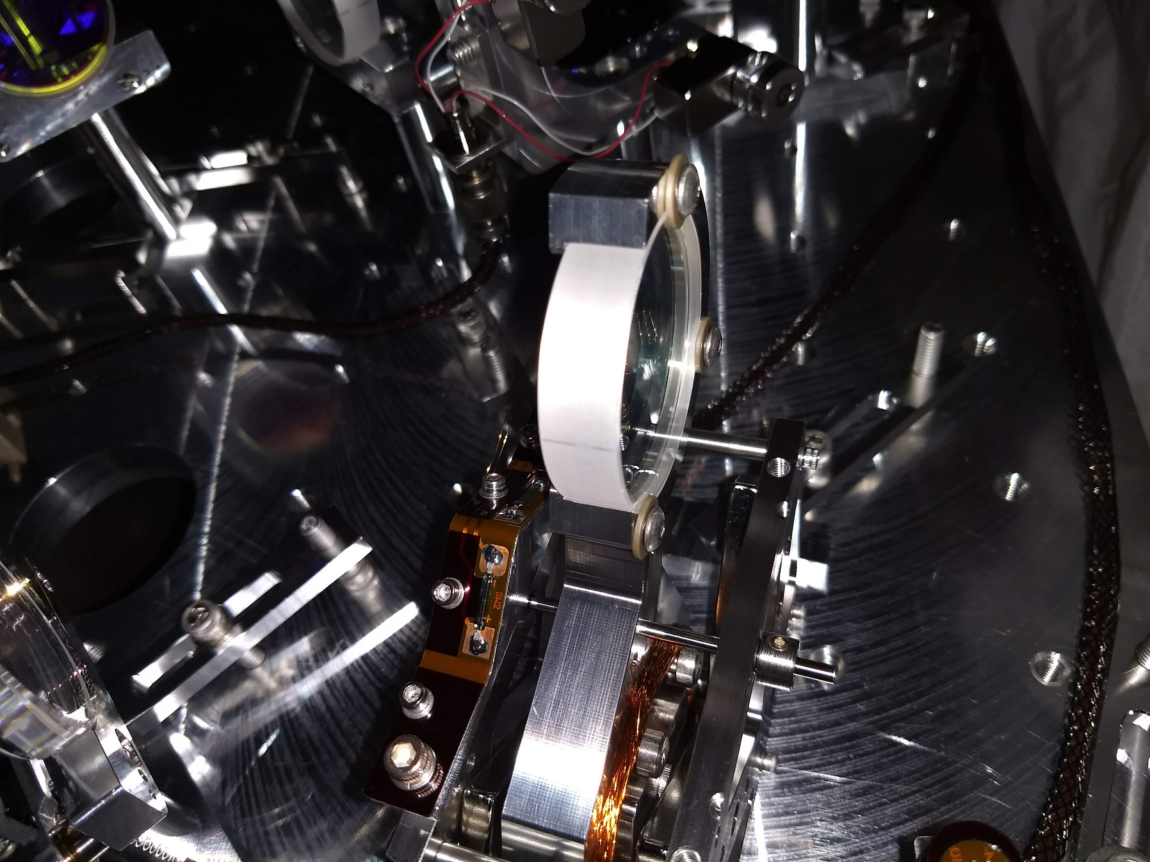
{Kyle, Chandra}
Kyle vented the vertex at 8am (~ 2 hr vent) and then we both climbed on beam tube, each wearing a safety harness tied off to one single crane hook, to remove the 12" conflat flange blank and replace the leaky copper gasket on port located just before NEG #1. Chandra inspected the knife edges on blank and mating flange - all looked good. We noticed a discolored spot on both flanges about the size of a nickel outside of the knife edge on flat flange surface. We wiped it with iso-wipe. It is a cloudy gray color with hints of red/orange outlining - could be rust/corrosion. No photos taken because all four hands were needed and we didn't want to risk dropping anything inside the beam tube! Purge air was flowing strong while the blank was off (off for less than one minute). Old gasket came off with my gloved fingers. New gasket was torqued with flanges metal-to-metal, and we starting pumping down vertex at 10:50 am local.
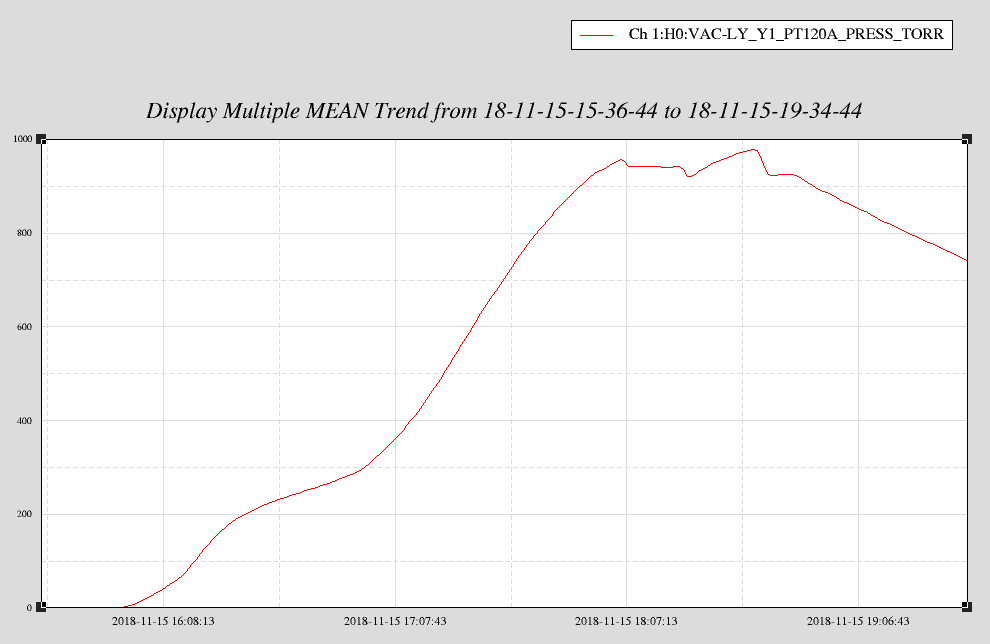
Rough down pressure curve comparisons of EY and vertex. No surprise that vertex takes longer to pump given pump speed for given volume. We expect to be on turbo pump sometime tomorrow and will leak check either later in the day or Monday.
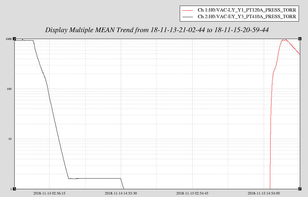
Measured dew point of vent air was -41C. I forgot to measure the dew point of the pressure equalization "blow down" air just prior to the start of the pump down.
The laser was found off this morning. The 70W amplifier flow watch dog was tripped.
In preparation for todays vacuum activities I shut down High Voltage supplies in the corner station
Shut down
ITMx, ITMy, SR3 Ring heater chassis
Verified ITMx, ITMy ESD power supplies still off.
Verifed Ham6 Fast shutter still off
Shut off OMC/SQZ PZT power supply
Made sure all Picomotors were in Disabled state
Turned of OPO TEC heater servo.
(Niko, Corey, Hugh, Keita, Georgia, Craig, Richard, Fil, Ed)
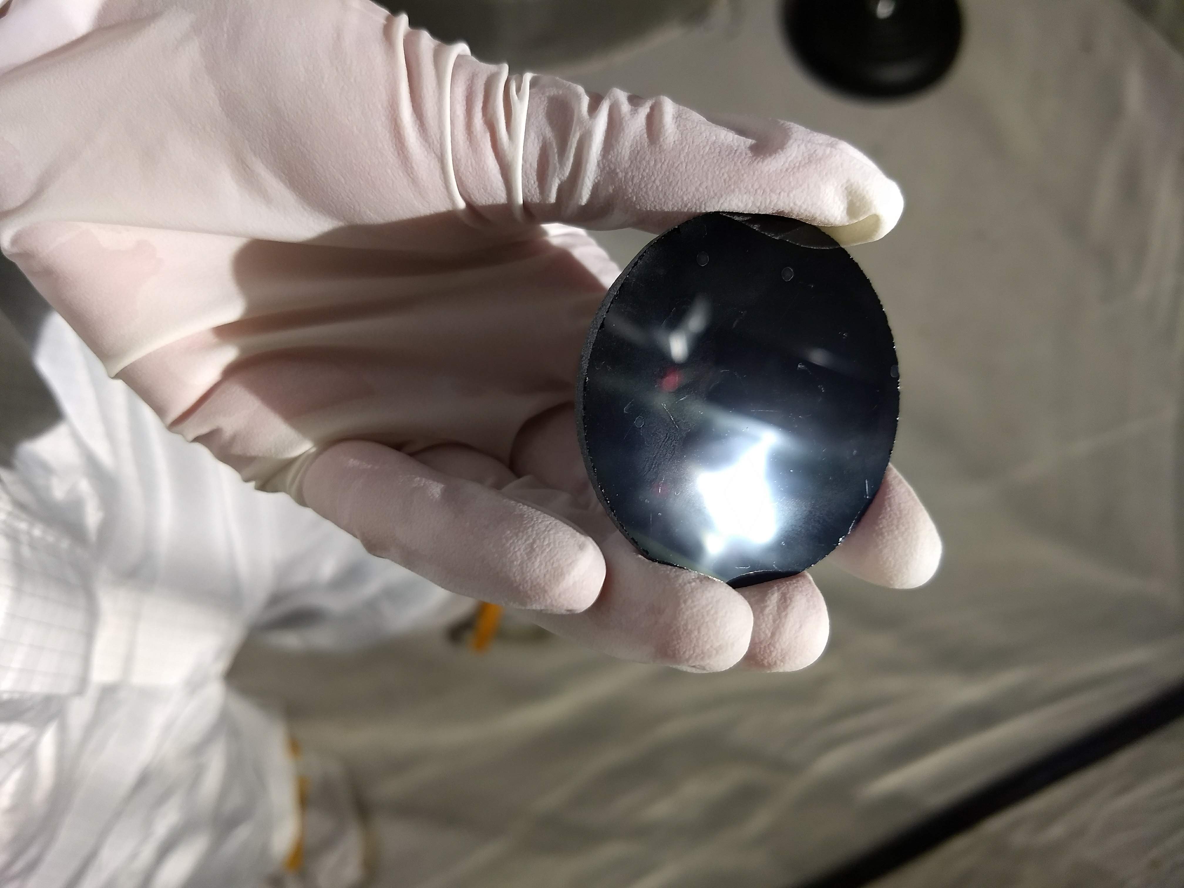
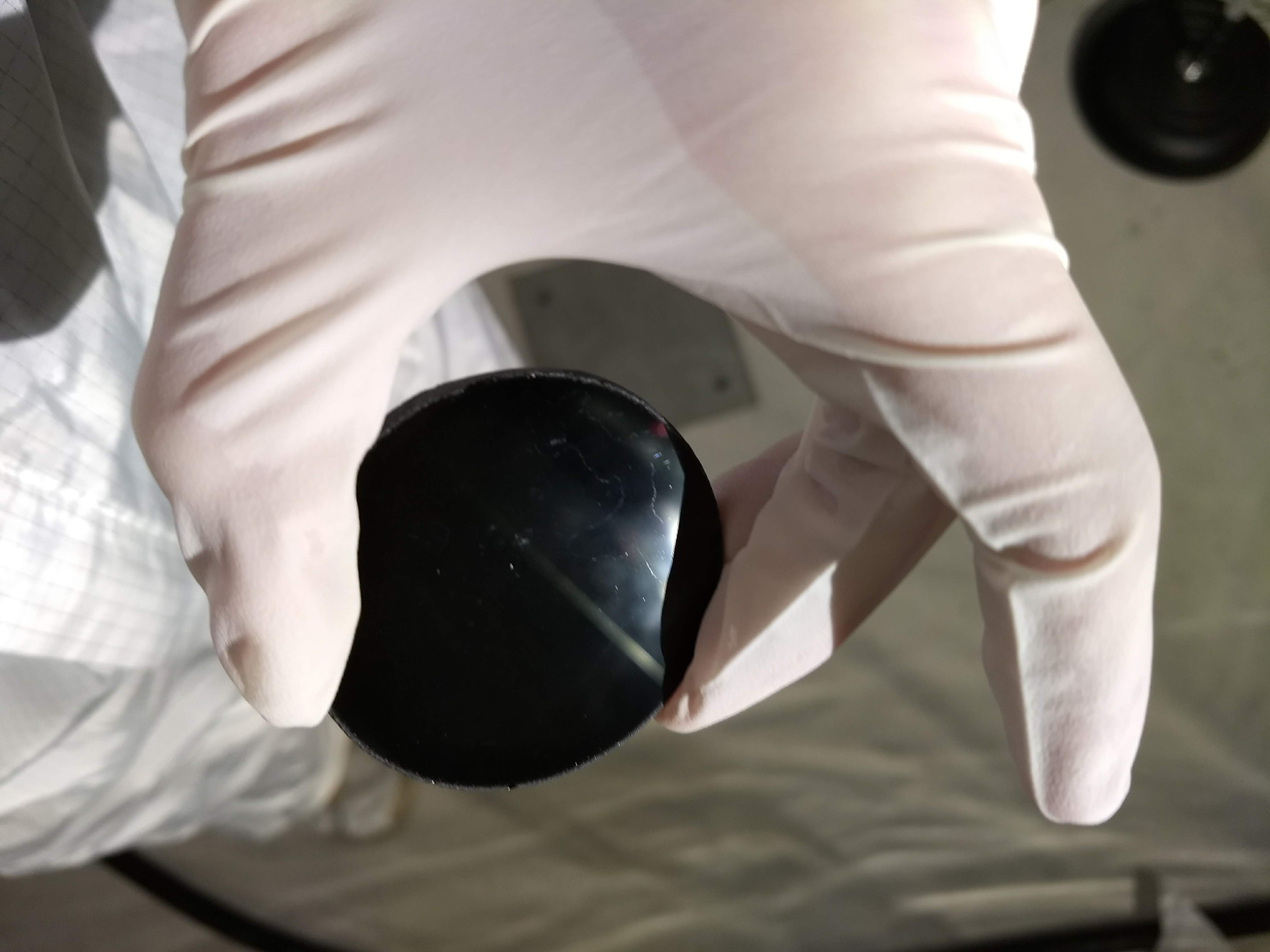
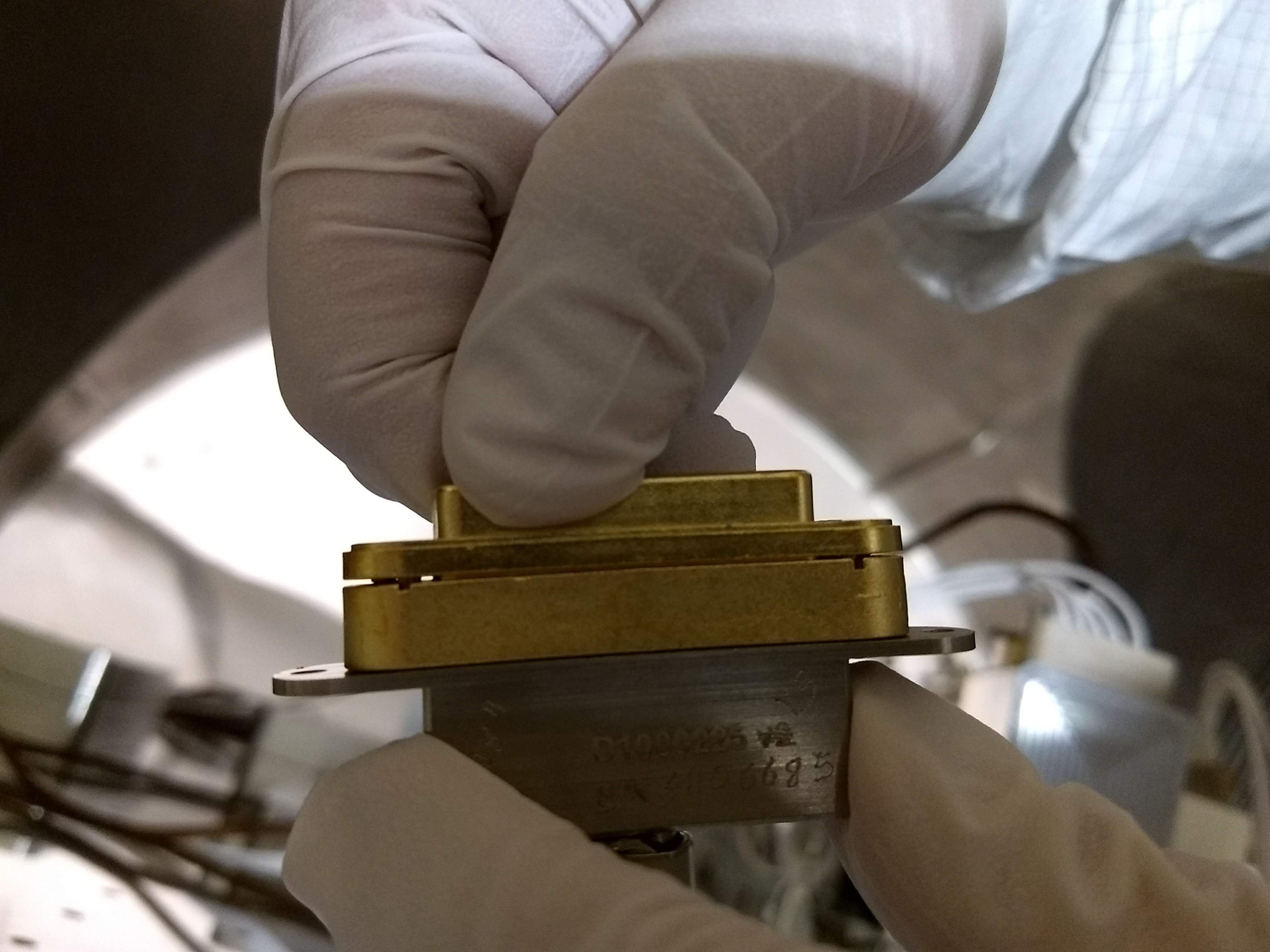
Today was the big day to squeeze in a variety of HAM1 Tasks. Once the doors were removed this morning, a suite of activities ensued:
Hugh will post specifics for L4C installation and for remaining tasks (and I will post photos).
Keita will post specifics for REFL_B PD installation.
Since, there has been a recent search for the D1300278 cables, and just for documentation, wanting to update this alog to note that the cable for this new REFL PD (LSC REFL B) was D1300278-V2-S1301459 (the shorter 106" long cable) and entered into ICS for this installation in Nov2018.
Following on from the EY ESD repair work: Once the pressure at End Y was low enough, Patrick T and I went out to turn on the high voltage and check that the ESD is operational.
We turned the HV supplies (outside the VEA) back on at 5:03pm local time, we then turned on the switches on the back of the low voltage ESD chassis (inside the VEA).
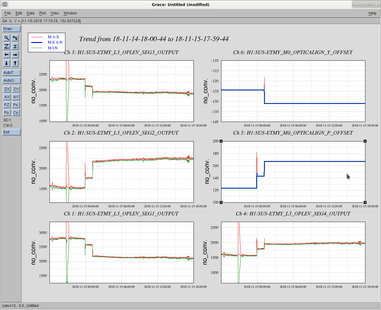
We did the same test that Fil and I ran in May - alog 41772 - driving the ESD quadrants at the OUTF stage (4.3 Hz, 30000 Cnts drive at the excitation point), and looking at the response on the optical lever. We didn't see a response to the LR quadrant drive, compare red trace to other traces in the attached screenshot, very perplexing. Could the problem be at the feedthrough?
We did no further tests this evening.
This is disheartening. It is possible to tell pretty much exactly where the break is. Look at T1800199 for a note I wrote detailing the method for finding the open circuit in a cable run. You will certainly know where in the chain the flaw exists. Richard and Fil are familiar with the technique. All things are obvious in retrospect, but we should have done this analysis method prior to going into the chamber. I was so taken by the possibility of the failure at the end of the cable nearest the optic, that I didn't think about alternative possibilities.
The feed through is tested when the continuity test is done. The pigtail that is in place is not removed so it is not the feed through.
The ETMY Oplev segments seem to be responding when I repoint the optic, so doesn't look like the Oplev readback signals are a problem.
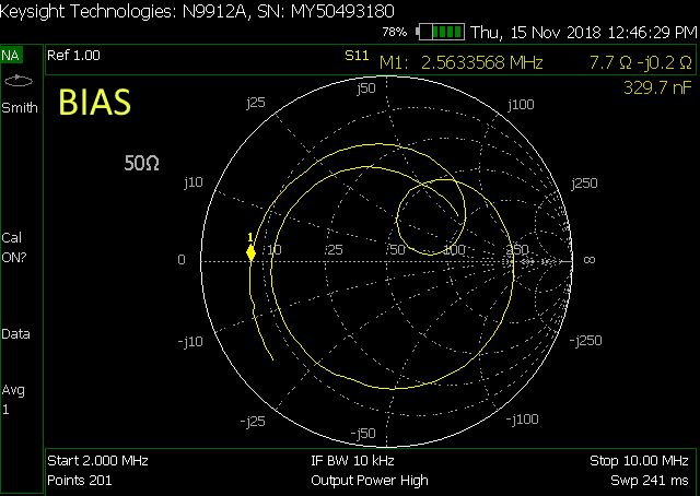
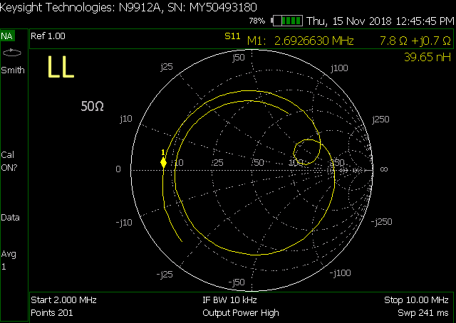
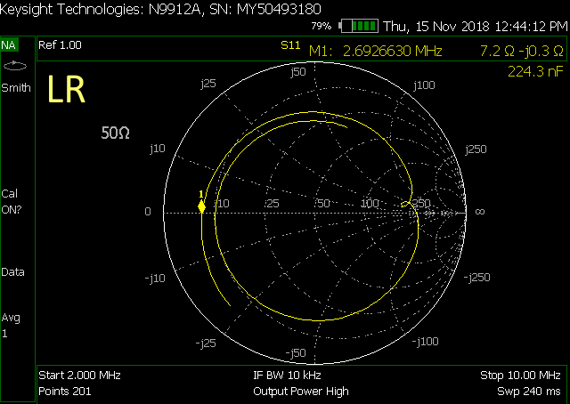
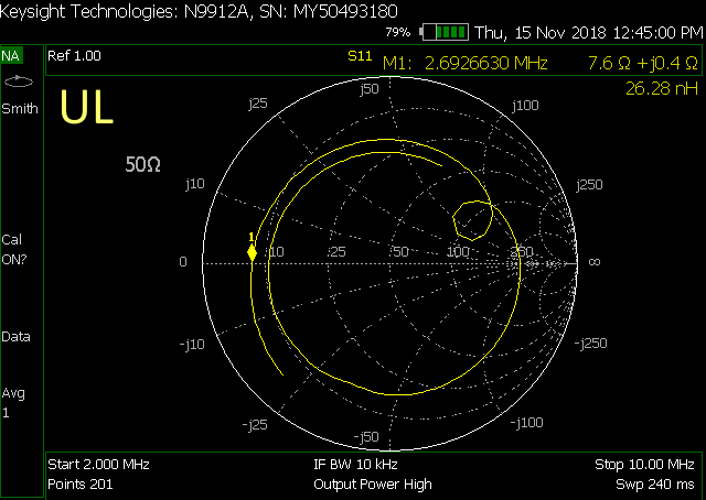
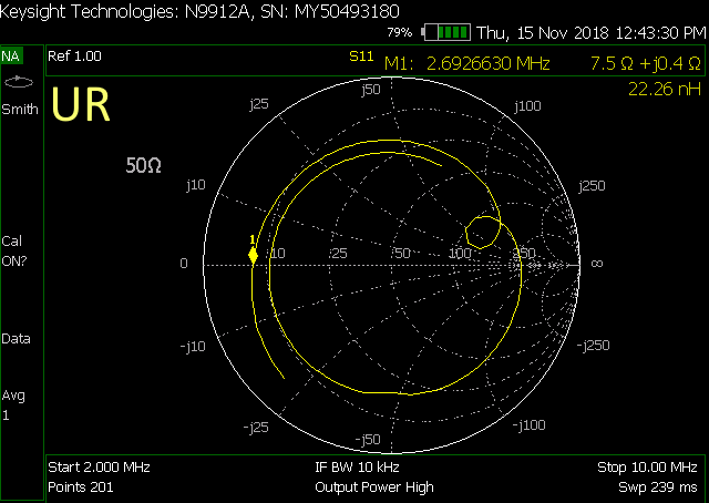
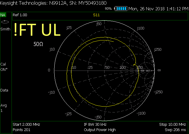
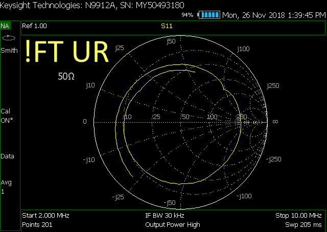
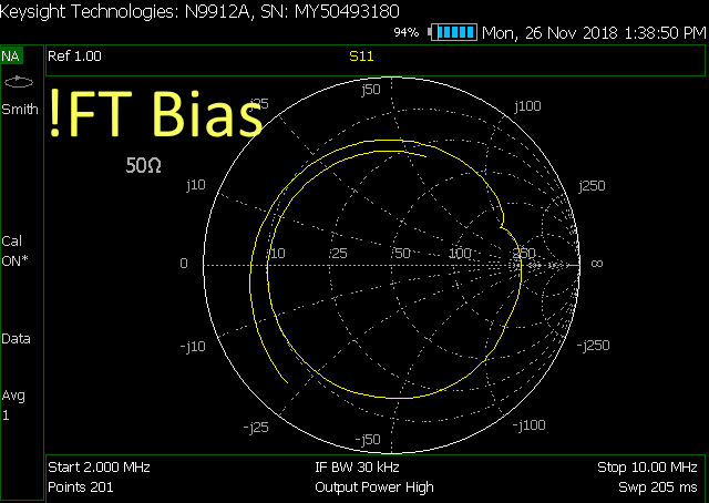
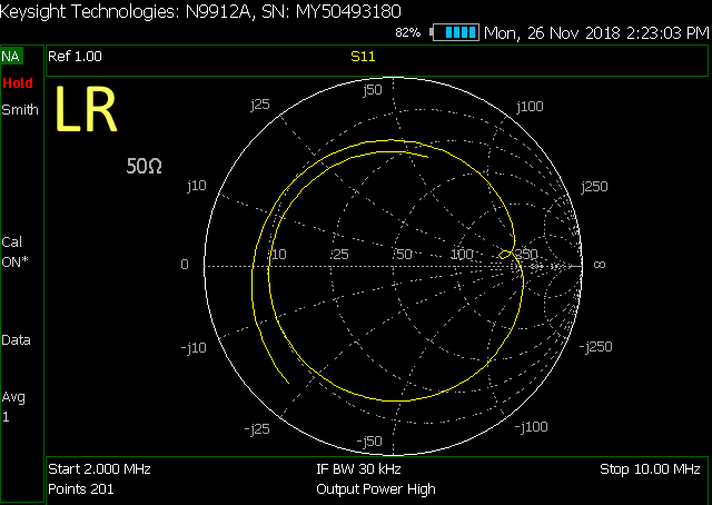
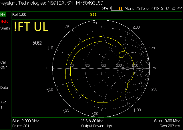
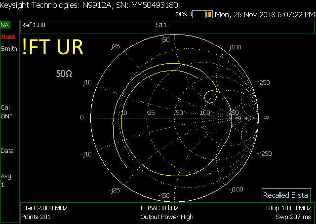
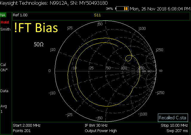
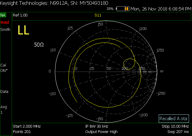
We looked at the cables using the FieldFox method recommended by Rich, T1800199 and here are the results. Our Field Fox is limited to 2MHz on the low end.
Bias cable ends at 64' from the ESD chassis
UR, LR, UL, and LL all end at 60' from the ESD chassis.
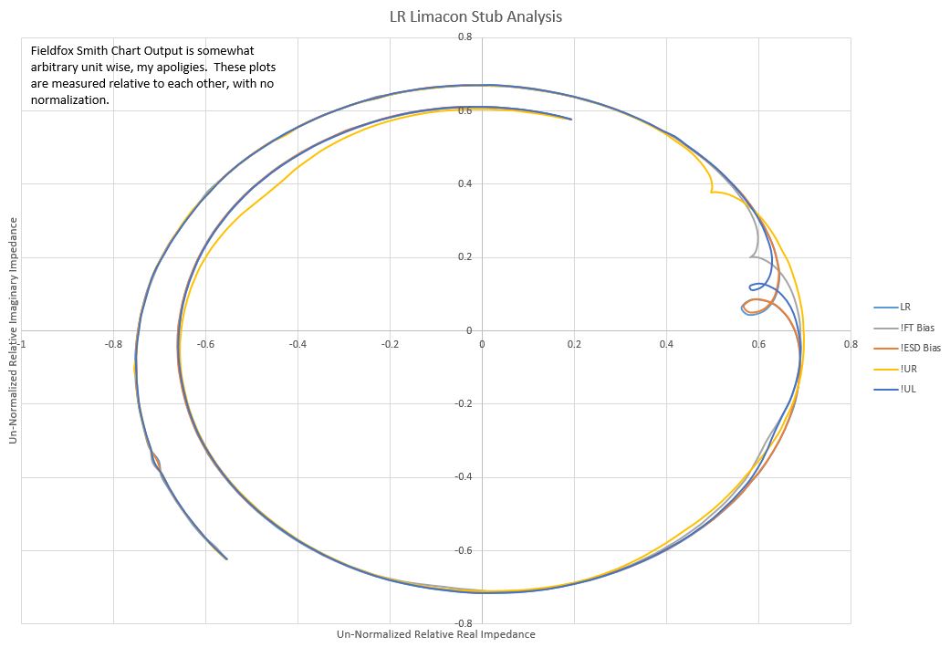
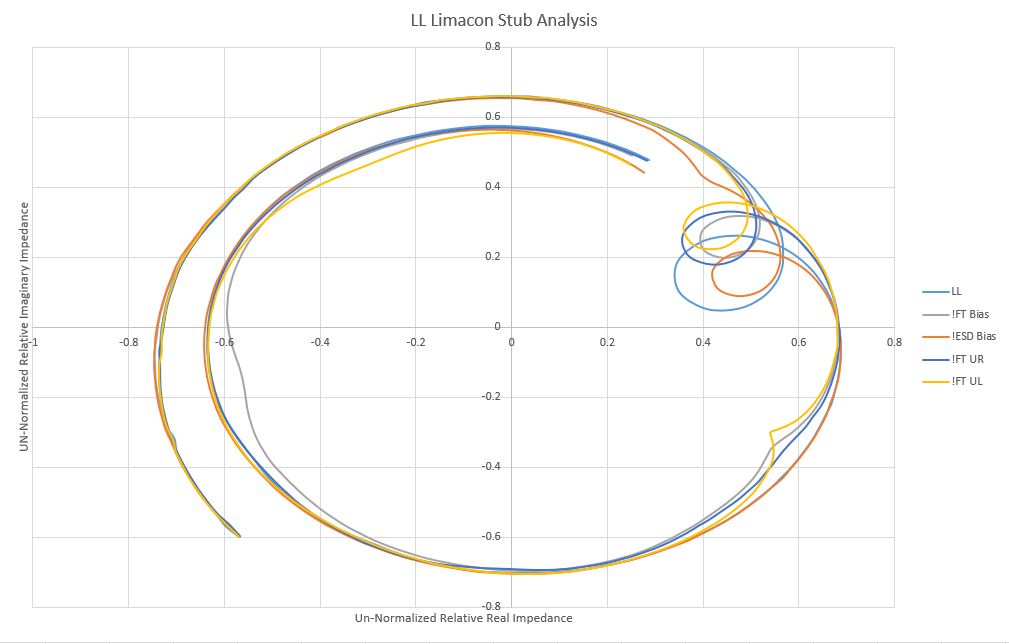
We noted a difference in the LR reflections so we took screen shots of each quadrant. I believe the length of the loop corresponds to the length of reflection on the test mass. The loop on the first reflection of the bias trace is quite large. The loop on the working quadrants are seemingly equal and smaller than the bias. The loop on the LR quadrant is very small.
Note: Fil did the same open circuit test in May. The results of the electrode lengths are here, alog 41861.
It makes sense that LL is longer than the upper quadrant electrodes (UL and UR) given the extra length of electrode around the barrel of the AERM. LR being shorter seems to suggest a break close to the optic.
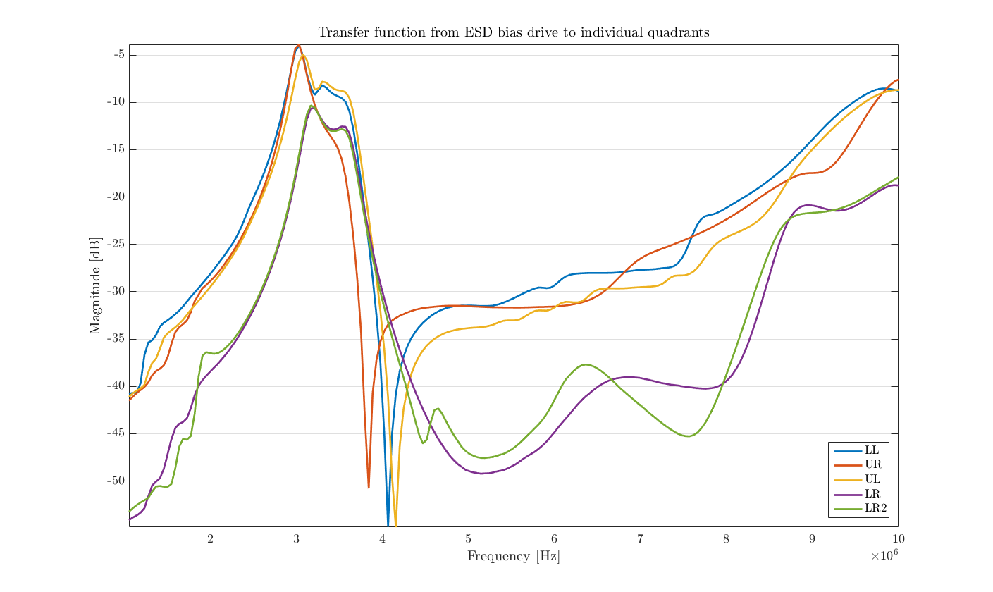
After speaking with some of the team, and reviewing Marc's data: 1. It would be a good idea to take the transfer function at RF (say 2 to 10 MHz sweep) from the air-side coax leading to the bias, out to each of the 4 quadrants. By examining these 4 transfer functions for symmetry, we can strengthen the case for there being a break in the gold mask on the LR quadrant of this optic. The connection from the incoming wire to each of the 4 quadrants is made by little soldered gold tabs. Were one of these tabs to break free, or if the pin that's soldered to the first tab on the top of the barrel of the reaction mass to come undone, it may account for the existing symptom. 2. When closely examined, the RF data taken by Marc does have 2 asymmetries in the LR plot vs the other 3 quadrants. The fact that the residual impedance at the first marker frequency (~2.69MHz) is different (capacitive for LR and slightly inductive for the others) is noteworthy, but not stunning. The precision of this type of measurement relies on knowing the characteristic impedance of the entire cable assembly. Given that these assemblies end in a single wire strung into space, it's not immediately compelling to see slight differences, and indeed there is variation in the other "good" quadrants. However if you couple this observation with the funny looking loops seen on the right side of the plots, the story gets more interesting. The funny loops are likely to be parasitic couplings to another resonant element (bias electrode?) in the cable/ESD system. A smaller loop (as seen in LR) indicates less coupling. This would fit the model of there being a break somewhere in the gold pattern distribution that exists on the reaction mass. The coupling is likely to be a cross coupling to the bias element through parasitic electro-magnetic coupling. when taking these transfer functions, it is likely that there will be enhanced coupling evident at the frequency of the loops as seen in Marc's data (manifesting in a lower loss in the RF transfer function). 3. Continuity tests are done to the top electrodes on the reaction mass barrel at the 12 o-clock position. If there was a break further down the chain (like the gold bond wires that are soldered on), then the continuity test would not catch that. Calum thinks we used to examine the gold bond wires when we did incursions relating to ESD troubles. I don't know if that was done during this vent cycle. I ran a simulation of a coaxial cable with an open lossy resonant termination, and was able to mimic the loops and overall response seen in Marc's data.
Fil, Marc, Georgia
We went back down to End-Y to run some more tests on the ESD, including that mentioned in the first point of Rich's comment.
Following tests were redone yesterday afternoon.
Looking at feedthrough with pigtail connector attached checked for shorts across:
1. Pin to Shield on each individual SHV connector
2. Pin to Pin on all SHV connectors
3. Shield to Shield on all SHV connectors
4. Pin to Chamber GND on each individual SHV connector
5. Shield to Chamber GND on each individual SHV connector
All tests passed.
Place a T adapter in line with the LR segment and monitored voltage going into chamber. Same voltage was observed when connected to chamber vs not connected to chamber.
The AERM solder joints at the optic were intact in Jan 2018 during the install (alog 40336) - although this picture doesn't show the side shot for the LR.
It's hard to image that the solder joints (large and look very good in picture) have come undone. I know for a fact that upon my inspection of the top 5 pins while in-chamber this last Tuesday, the pins were still landed well and the solder/pin joint look the same as in this picture from Jan. It is very difficult to inspect the "bridges" that connect the barrel gold traces to the face traces, and I did not look specifically at those on Tuesday.
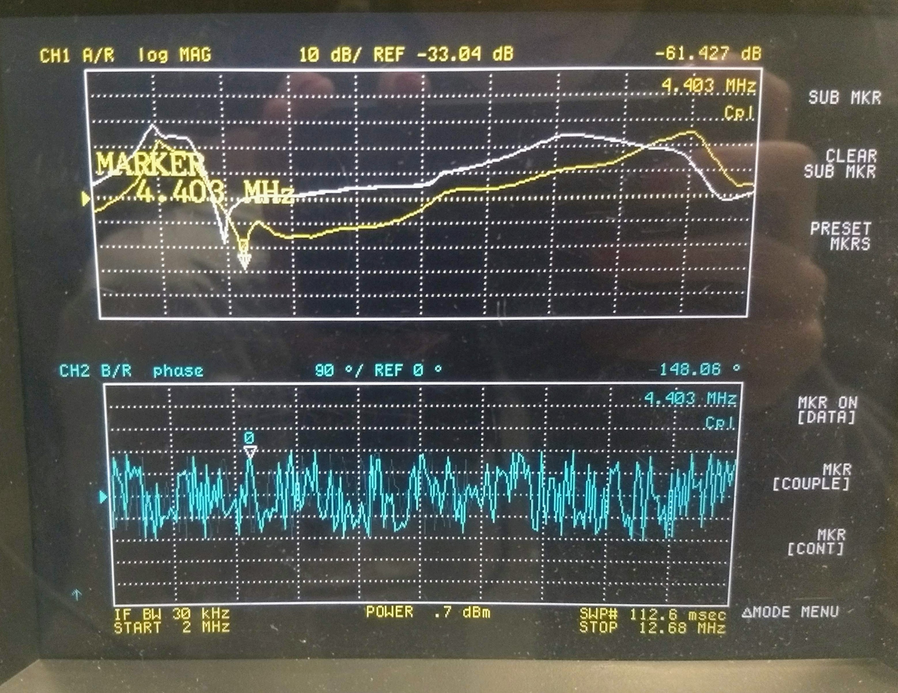
We have some new scans from ETMY Annular End Reaction Mass (AERM), LR quadrant. We tried scanning the LR quadrant while changing the other cable configurations to determine where the coupling is strongest. On the plot we can see the LR signal as it was in prior scans. We then disconnected the Bias at the ESD which shifted the trace slightly but not significantly. Next we disconnected the Bias at the feed through and saw a much larger shift. Next we reconnected the Bias at the feed-through, and disconnected the UR signal. This made the most difference to our trace which leads me to believe that there is more coupling between LR and UR, than there is between LR and Bias, which should be the case if we are disconnected at the joint on the side of the AERM. Disconnecting the UL signal made little difference to the coupling.
We scanned the LL quadrant in the same way we scanned the LR quadrant, I will post it here as a way to compare the known good lower quadrant with the sketchy lower quadrant.
Terry Nutsinee Haocun Sheila Fabrice
We believe that the first dichroic used to separate the squeezed beam from the reflected green light from the OPO is mounted backwards, and that this a likely explanation for the extra losses seen with homodyne measurements 43948.
Nutsinee and Daniel locked the OPO this morning, Nutsinee will add more information about that. We tuned the temperature to have co-resonance without nonlinear gain, we found the third co-resonance away from phase matching at 41.5 C, but still had some nonlinear gain. We went to the 5th co-resonance temperature, 51.15C. Once we had ZM1 aligned and increased the seed power injected to 14 mW measured at the seed launch PD we had a nice beam to use for the loss measurement and alignment checks.
When we started to measure powers in the transmitted seed, we saw that there were three beams, and that these beams were indeed seed light not green. We measured 330uW of seed right after the first dichroic, the three beams get closer near the second dichroic but are separated enough by the time they reach the Faraday rotator that only the center one passes through the rotator, where we measure 270uW, or 80% of the light. This dichroic is E0900491.
Other things done today:
We measured the green power transmission into the chamber as 44%. Fabrice was happy, so we are happy
| before coupler on ISCT6 | 14.1mW |
| out of collimator in HAM6 | 6.23mW |
Fabrice + Kyle torqued the feedthrough. We also added one more peek cable bracket the routing of the new fiber. We did this because when we plugged in the new fiber we did not route it under the dog clamp that the ordinal fiber was routed under on the east side of the table, which made Fabrice concerned about rubbing in the loop that the fiber makes to avoid shorting the isolation.
Glad you figured that out!
The overall throughput of the fiber chain is probably the new best in the history of green fiber science, so I am also happy. Let's hope it stays that way.
Here's a couple of photos of the beam coming off the backward dichroic. The first picture was the beam reflected off the first dichroic (closest to the OPO). Note that if you block the green and just look at the seed the red beams are right on top of the green. The second photo is after the 2nd dichroic mirror, just before the polarizer.


Note on OPO locking
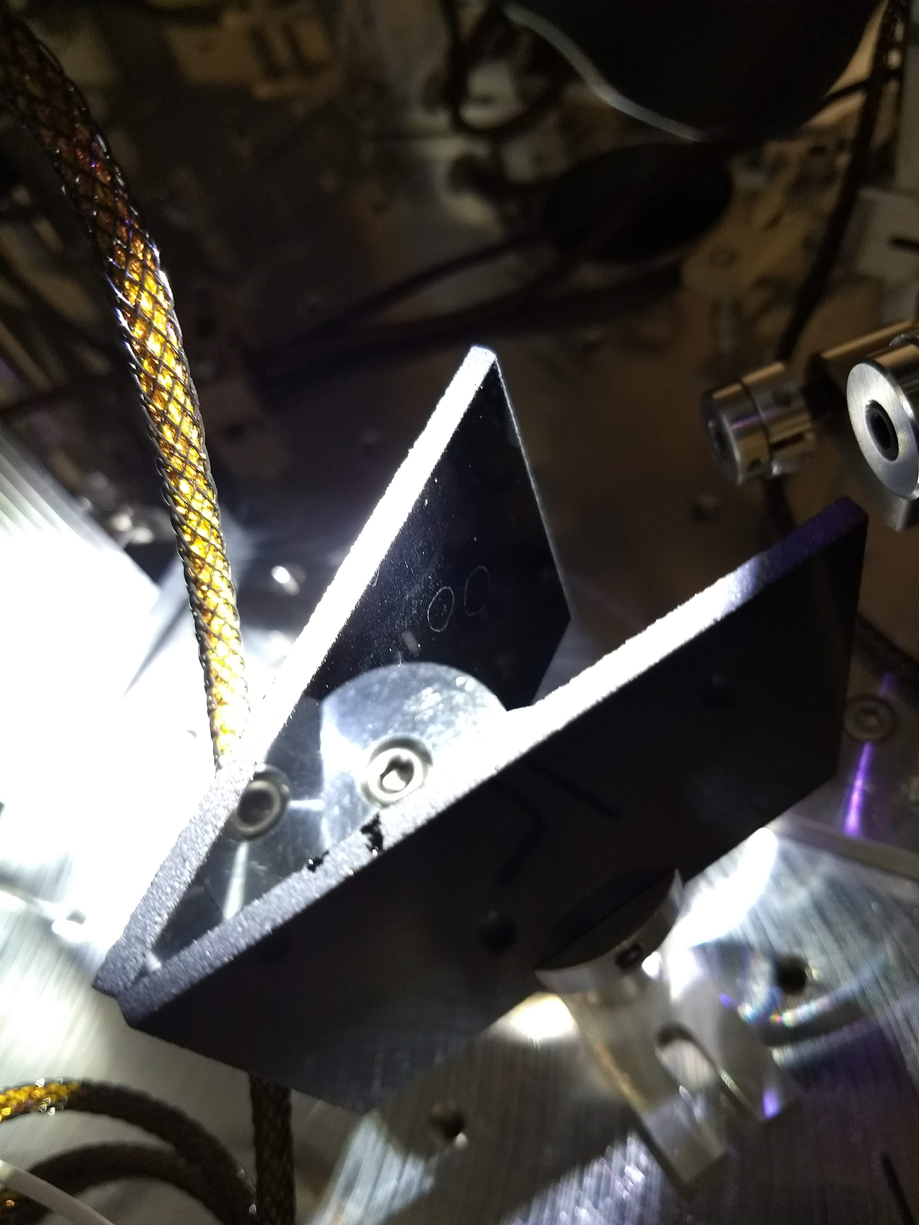
Attached a spectrum, a transfer function, and the settings that worked. We locked the laser to the OPO just like how we have been doing but using PZT only. We had much stronger purged air than the last time (April vent) when we locked in-air successfully so the purged air has to be turned down. The UGF was ~22kHz with roughly 20dB gain at 1kHz, and no boosts were on (2nd boost in the common path can be turned on unreliably).
J. Oberling, P. King
Quick and dirty summary: mode matching work is still ongoing.
All this work was done with the ISS OFF and the ISS AOM removed from the beam path. Using the beam propagation measurement we took yesterday, Peter generated a mode matching solution and implemented it this morning. Tweaking the lenses around, we saw as much as ~53W transmitted through the PMC, but couldn't get any more than that. At this point the visibility (as calculated by measuring the locked/unlocked voltage of the PMC locking PD) actually looks pretty good at ~91%, but there is something odd going on: the power transmitted through the PMC is lower than the visibility suggests it should be. For example, we currently have ~51.8W transmitted through the PMC and ~14.2W reflected, giving a total power at the PMC of ~66W; this means we are only transmitting ~78.5% of the PMC incident power. Ideally, with a visibility of ~90% we would expect to be transmitting closer to 59.4W. We are currently looking for things that could cause this behavior, as it indicates our PMC throughput issue is not caused by shoddy beam quality.
Another odd bit, the visibility gets lower as the power increases. I measured the visibility at several different input powers:
| Input Power (W) | Visibility (%) |
| 40.3 | 96.2 |
| 50.1 | 93.3 |
| 55.2 | 92.6 |
| 60.2 | 92.0 |
| 65.0 | 91.4 |
This also appears to indicate that something other than the beam quality is causing our PMC throughput issues. Inspecting some of the optics in the beam path we found that both mode matching lenses were dirty; I cleaned them but it didn't appear to help at all. Cheryl also pointed out that there appears to be some scatter issues with mirror AMP_M03. While we didn't do anything with this mirror today, this is another item we can check. We are going to think on this overnight and get back to it in the morning.
Cavity losses are ruled out based on fabrication data outlined in T1700453.
Richard, Fil, Daniel
We are using the spare channel on the IMC demod board for REFL_B. This 2-chn demod has the new interface board which implements whitened readbacks for I and Q. The DB9 cable to the ADC was borrowed from the 4th port of the WFS interface in ISC-R4 (ISC_425). This port was never used.
Channels names are H1:LSC-REFL_B_RF9_I_ERR and H1:LSC-REFL_B_RF9_Q_ERR. We also get H1:IMC-REFL_RF24_I_ERR and H1:IMC-REFL_RF24_Q_ERR for free.
The 9.1 MHz LO is hooked up through a delay line. I measured 10dBm at the input to the LO. Earlier today the out-of-vacuum cables to the HAM1 flange were installed as well. The DC readback is through the 2nd port of the LSC PD interface in ISC-R1. The channel name is H1:LSC-REFL_B_LF_OUT. A separate RIN channel is also available.
Injected an RF signal into the RF input of the demod and checked that the readbacks and whitening are working. The whitening is 2 zeros at 2.98Hz and 2 complex poles at 30Hz with a Q of 0.57. The low frequency gain is 1, whereas the high frequency gain is 40.1dB.
Jeff B. phoned me while I was doing this as he had noticed a very large spike in particulate in the Y-end VEA which exactly correlated with my having done this. Investigation revealed that the Y-end Turbo's local scroll pump never got a particulate filter installed at its exhaust - Ooops! -> I located this unit and will install it.
Also, the chilled water booster pump used with the QDP80 is now leaking at the pump end -> will put this on the list.
FRS ticket 11827
11/15/2018
I installed the particulate filter on the exhaust of the Y-end local scroll pump.
Keita, Richard, Corey, Craig, Georgia
For now,
These are finalized/installed/checked on Saturday after the PSL beam becomes available and IMC locked in vacuum.
Here is some experience on cleaning the foggy patterns on black glass: https://nodus.ligo.caltech.edu:8081/OMC_Lab/283 https://nodus.ligo.caltech.edu:8081/OMC_Lab/283
[Sheila, Fabrice, Nutsinee, Terry, Haocun]
Summary:
We have OPO coupling 89% 00 mode, alignment >~95%, mode matching >~95% and polarization mode ~2%.
I will add more details with numbers later.
Detailed measurements:
These numbers are the best ones we tried to take because the signal was noisy in air.
Calculation:
Here's a picture of the scan. Will go back and save the data properly later.