richard.savage@LIGO.ORG - posted 19:32, Friday 09 November 2018 (45178)
Push-to-connect water fittings for the 35-W amplifier in the FrontEnd laser
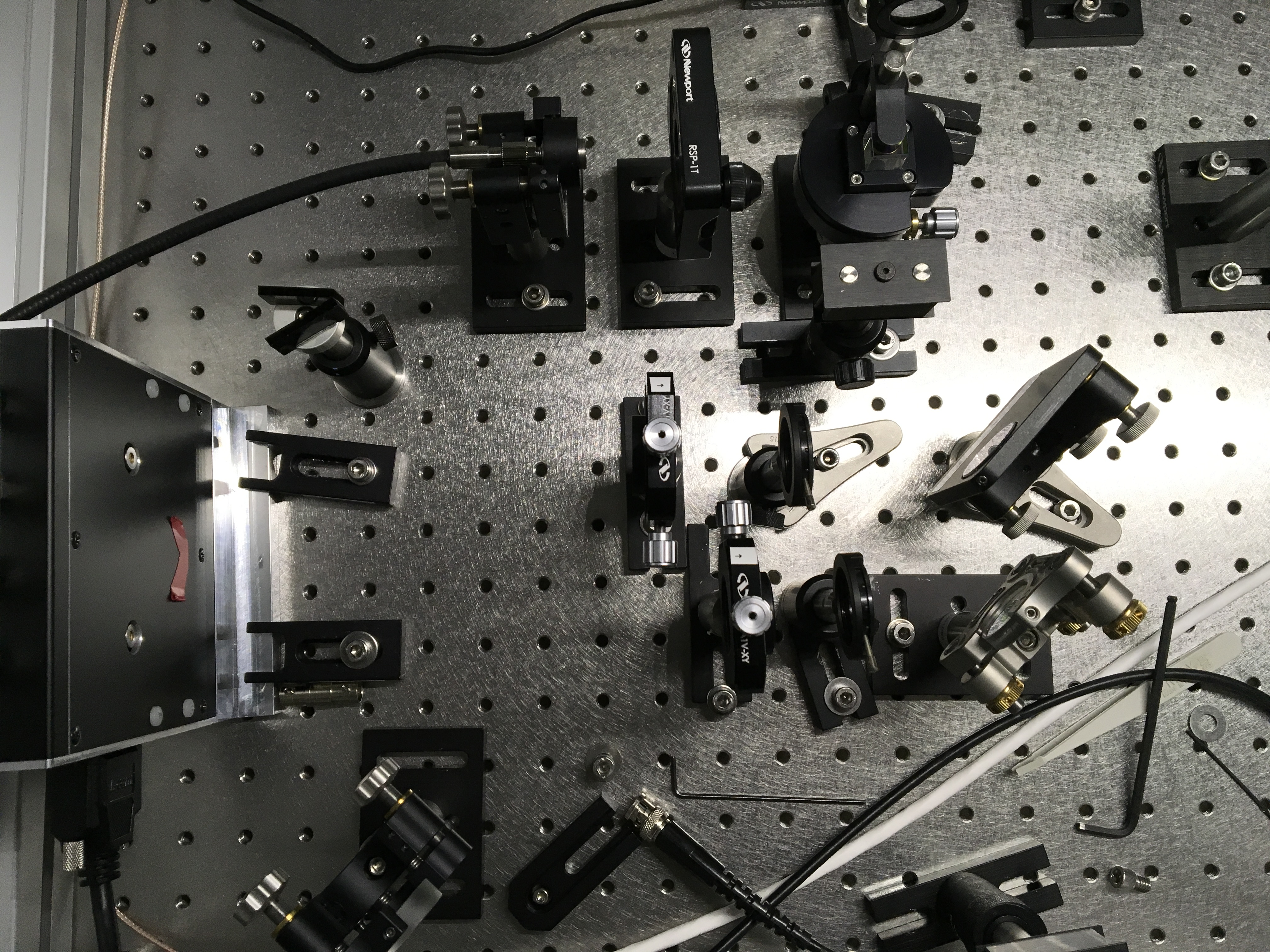
Following up on the work to replace the "dripless" quick-connect fittings in the 35-W amplifier in the PSL FrontEnd laser, see Link, today I installed the new fittings in one of the spare FrontEnd lasers.
These fittings accommodate 8 mm O.D., 6 mm I.D., tubing from the outside and transition to the 6 mm O.D., 4 mm I.D. tubing that is connected to the crystal holders in the laser head.
The installation proceeded as expected and confirms that this scheme should work for the laser currently operating in the H1 PSL. We plan to do the same fitting swap in the H1 laser room next monday.
Photos are in the attached .pdf file.
Non-image files attached to this report